

Page 1

2 YEAR
User’s Guide
Shop online at
omega.com
e-mail: [email protected]
For latest product manuals:
omegamanual.info
SM
TX402
Head Mount TC/RTD Input
Transmitter RFID
Page 2

Introduction / Introduzione
Thanks for choosing a Omega device.
The TX402 converts a signal obtained from temperature sensors PT100, PT1000
or NI100 (with a 2, 3 or 4 wires connection) into a current signal for 4..20mA loop
(2 wi res).
Main features are:
• High accuracy;
• 16bit conversion;
• Programmable by RFid (NFC);
• Input -10..+70 mV
• 2624 Word non-volatile memory (circular buer) for data-logging with
sampling time selectable by the user;
•
Possibility to rescale the output 4..20mA compared to temperature input value;
• Field calibration to compensate eventual errors (Gain and Oset);
• Compact dimensions;
• The software RF Programmer (available for download on www.omega .com
and the TX400-RFI D allow:
- complete congurability of the device;
- download on PC of logged data;
- visualization/printing of the temperature - time trend
Grazie per aver scelto un prodotto Omega.
Lo strumento TX402 conver te un segnale di temperatura acquisito attraverso
sonde PT100, Ni100 con collegamento a 2, 3 o 4 li o TC in un segnale
normalizzato in corrente per loop 4..20 mA (tecnologia 2 li).
Le caratteristiche dello strumento sono:
• Elevata precisione;
• Conversione della misura a 16 bit;
• Programmabilità via RFid (NFC);
• Ingresso -10..+70 mV
• 2624 Word di memoria non volatile (buer circolare) per data-logging con
tempo di campionamento impostabile dall’utente;
• Possibilità di riscalare l’uscita 4.. 20mA rispetto all’ingresso in temperatura;
•
Taratura in campo per recuperare eventuali errori delle sonde (Gain e Oset);
• Ridotto ingombro;
• Tramite il software RF Programmer (scaricabile dal sito omega.com) e il
programmatore TX400-RFID, è possibile fare:
- congurabilità completa del convertitore;
- download su pc del logging registrato;
- visualizzazione e stampa della curva temperatura - tempo
Page 3
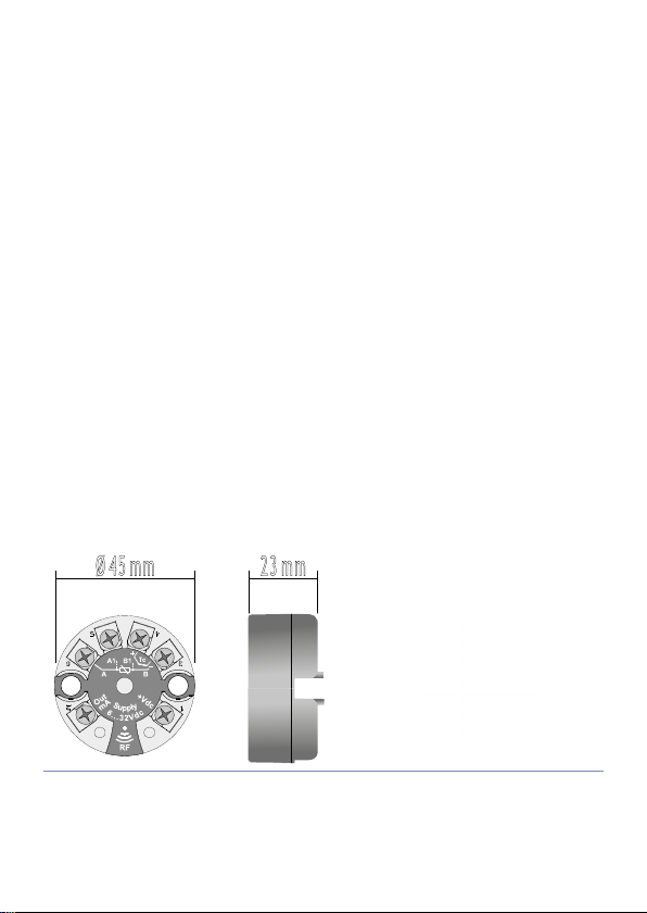
1 Safety guide lines / Norme di sicurezza
Ø 45 mm 23 mm
Read carefully the safety guidelines and programming instructions contained in
this manual before using/connecting the device.
Only qualied personnel should be allowed to use the device and/or service it
and in accordance to technical data and environmental conditions listed in this
manual.
Do not dispose electric tools together with household waste material. In
observance European Directive 2002/96/EC on waste electrical and electronic
equipment and its implementation in accordance with national law, electric tools
that have reached the end of their life must be collected separately and returned
to an environmentally compatible recycling facility.
Prima di utilizzare il dispositivo, leggere con attenzione le istruzioni e le
misure di sicurezza contenute in questo manuale.
L’utilizzo/manutenzione è riservato a personale qualicato ed è da intendersi
esclusivamente nel rispetto dei dati tecnici e delle condizioni ambientali
dichiarate.
Non gettare le apparecchiature elettriche tra i riuti domestici.
Secondo la Direttiva Europea 2002/96/CE, le apparecchiature elettriche
esauste devono essere raccolte separatamente al ne di essere reimpiegate o
riciclate in modo eco-compatibile.
2 Dimensions and installation / Dimensioni e
installazione
Page 4

1 Technical Data / Dati tecnici
1.1 General data / Caratteristiche generali
Operating range
1
Range funzionamento
Current output
2
Uscita in corrente
Functional insulation
3
Isolamento funzionale
Output resolution
4
Risoluzione in uscita
Upper Linearity Limit
5
Limite linearità superiore
Lower Linearity Limit
6
Limite linearità inferiore
Failure output
7
Uscita guasto
Current output protection
8
Protezione uscita in corrente
Rejection
9
Reiezione
Max transmission error
10
Max errore di trasmissione
11 EMI < 0,5%
Cable resistance
12
Resistenza cavi
Temperature coecient
13
Coeciente di temperatura
Sampling time
14
Tempo di campionamento
Response time (10..90%)
15
Tempo di risposta (10..90%)
Sealing
16
Grado di protezione
Conformity
17
Normative
6-32 Vdc
4..20 mA (2 wires) / 4..20 mA (2 li)
1K Vac
2 μA
f.s. + 5°C
f.s. - 5°C
selectable 21mA, 3,8mA or anyone
selezionabile tra 21mA, 3,8mA o nessuno
30 mA approx.
30 mA circa
50- 60 Hz
greater between 0,1% f.s. or 0,2°C
maggiore tra 0,1% f.s. o 0,2°C
max 20Ω
< 100 ppm
300 ms
approx. 600 ms
IP 20
CE, EN 61000- 6-4, EN 61000-6-2
Page 5

1.2 Thermo-mechanic features / Caratteristiche
termomeccaniche
Operating temperatu re
1
Temp. di funzionamento
Humidity
2
Umidità
Storage temperature
3
Temperatura
magazzinaggio
Connections
4
Connessioni
Conductors section
5
Sezione conduttori
Wires strip
6
Spelatura conduttori
Enclosure
7
Custodia
Dimensions
8
Dimensioni
-40..+85 °C
30-90% @ 40°C (non condensing / non
condensante)
- 40 ..+105 °C
screw pins
morsetti a vite
2
1 mm
8 mm
nylon (PA66)
23 mm, Ø 45 mm
2 Input / Ingressi
PT100
Ni100
TC K Measuring range: -260..+1360°C / Range di misura: -260..+1360°C
TC S Measuring range: -40..+1760°C / Range di misura: - 40..+1760°C
TC R Measuring range: -40..+1760°C / Range di misura: -40..+1760°C
TC J Measuring range: -200..+1200°C / Range di misura: -200..+1200°C
TC T Measuring range: -260..+400°C / Range di misura: -260..+400°C
TC N Measuring range: -260..+1280°C / Range di misura: -260..+1280°C
TC B Measuring range: +40..+1820°C / Range di misura: +40..+1820°C
TC E Measuring range: -260..+940°C / Range di misura: -260..+940°C
Input mV
Measuring range: -200..+600°C / Range di misura: -200..+600°C
Connection: 2, 3, 4 wires / Tecnica di collegamento: 2, 3, 4 li
Measuring range: -60..+180°C / Range di misura: -60..+180°C
Connection: 2, 3, 4 wires / Tecnica di collegamento: 2, 3, 4 li
Measuring range: -10..+70mV / Range di misura: -10..+70mV
Page 6
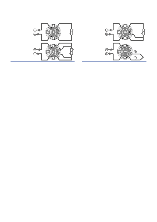
2.1 Connections / Connessioni
A B
A1 B1
+Vdc
Supply
6...32Vdc
RF
Out
mA
RTD
2 WIRE
4...20mA
6...32Vdc
RED
WHITE
A B
A1 B1
+Vdc
Supply
6...32Vdc
RF
Out
mA
RTD
2 WIRE
A B
A1 B1
+Vdc
Supply
6...32Vdc
RF
Out
mA
RED
RED
RTD
3 WIRE
4...20mA
6...32Vdc
4...20mA
6...32Vdc
WHITE
RED
WHITE
A B
A1 B1
+Vdc
Supply
6...32Vdc
RF
Out
mA
RTD
2 WIRE
A B
A1 B1
+Vdc
Supply
6...32Vdc
RF
Out
mA
RED
RED
RTD
3 WIRE
A B
A1 B1
+Vdc
Supply
6...32Vdc
RF
Out
mA
WHITE
RTD
4 WIRE
RED
4...20mA
6...32Vdc
4...20mA
6...32Vdc
4...20mA
6...32Vdc
WHITE
WHITE
RED
RED
WHITE
Cables colors according to IEC60751 / Colorazioni cavi come da IEC60751
WHITE
Pt10 0
Ni100
Pt10 0
Ni100
4...20mA
6...32Vdc
4...20mA
6...32Vdc
A B
Out
mA
A1 B1
6...32Vdc
Supply
RF
RTD
2 WIRE
+Vdc
RED
WHITE
WHITE
A B
Out
mA
A1 B1
6...32Vdc
Supply
RF
RTD
4 WIRE
+Vdc
RED
RED
Pt10 0
Ni100
TC
4...20mA
6...32Vdc
4...20mA
6...32Vdc
Out
mA
6...32Vdc
Supply
RF
+Vdc
3 Conguration / Congurazione
To congure this signal converter it is necessary to use a TX400-RFID and the
conguration software RF Programmer, available on www.omega.com. After
connecting the TX400-RFID via USB and activating the software, it is possible in
“EDIT” mode to congure the device selecting type of sensor, measuring range,
output for error signal and sampling frequency for the registration. The keys
“WRITE” and “READ” allow to write and read data on the devices quickly and
easi ly.
On the lower side of the display a list of all programmed devices is showed; it can
be printed to conrm that the programming has been completed successfully.
WHITE
A B
A1 B1
RTD
3 WIRE
RED
RED
Page 7

La congurazione di questo convertitore di segnale richiede l’utilizzo di
un base programmatore (TX400-RFID) e del sof tware di congurazione RF
Programmer scaricabile dal sito www.omega.com.
Dopo aver connesso tramite porta USB il TX400-RFID e attivato il software è
possibile con la modalità “EDIT” parametrizzare il dispositivo selezionando il
tipo di sensore, range di misura, uscita per segnalazione errore e la frequenza
di campionamento per la registrazione. Con i tasti “WRITE” e “READ” è
possibile scrivere e leggere i vari dispositivi velocemente e in modo agevole.
Nella parte bassa dello schermo appare la lista riassuntiva dei dispositivi
programmati, che può essere stampata per certicare la buona riuscita delle
operazioni.
4 Data Logger
This signal converter is provided with a datalogging function for the input signal.
Fixing the sampling tim e (1..3600 seconds) each time the loop 4 ..20mA powers the
device up, this will store the input value into a non-volatile memory. Through the
TX400- RFID it is possible to download / display / print all data.
Questo convertitore di segnale è provvisto di una capacità di storicizzazione
del segnale in ingresso. Fissando il tempo di campionamento (impostabile
tra 1 e 3600 sec.) ogni volta che il loop 4..20mA alimenterà il dipositivo
questo archivia il valore in ingresso su una memoria non volatile. Tramite il
TX400-RFID è possibile scaricare tutti i dati e presentarli a video o stamparli.
Page 8

Notes / Updates
Page 9

Page 10

omega.com [email protected]
U.S.A.: Omega Engineering, Inc., One Omega Drive, P.O. Box 4047, Stamford, CT 06907-0047 USA
Toll-Free: 1-800-826-6342 (USA & Canada only), Customer Service: 1-800-622-2378 (USA & Canada only)
Engineering Service: 1-800-872-9436 (USA & Canada only),
Tel: (203) 359-1660, Fax: (203) 359-7700
e-mail: [email protected]
The information contained in this document is believed to be correct, but OMEGA accepts no liability for any
errors it contains, and reserves the right to alter specifications without notice.
OMEGA ENGINEERING, INC. warrants this unit to be free of defects in materials and workmanship for a period
of 13 months from date of purchase. OMEGA’s WARRANTY adds an additional one (1) month grace period to
the normal one (1) year product warranty to cover handling and shipping time. This ensures that OMEGA’s
customers receive maximum coverage on each product.
If the unit malfunctions, it must be returned to the factory for evaluation. OMEGA’s Customer Service Department
will issue an Authorized Return (AR) number immediately upon phone or written request. Upon examination by
OMEGA, if the unit is found to be defective, it will be repaired or replaced at no charge. OMEGA’s WARRANTY
does not apply to defects resulting from any action of the purchaser, including but not limited to mishandling,
improper interfacing, operation outside of design limits, improper repair, or unauthorized modication. This
WARRANTY is VOID if the unit shows evidence of having been tampered with or shows evidence of having
been damaged as a result of excessive corrosion; or current, heat, moisture or vibration; improper specication;
misapplication; misuse or other operating conditions outside of OMEGA’s control. Components in which wear is
not warranted, include but are not limited to contact points, fuses, and triacs.
OMEGA is pleased to offer suggestions on the use of its various products. However, OMEGA
neither assumes responsibility for any omissions or errors nor assumes liability for any
damages that result from the use of its products in accordance with information provided by
OMEGA, either verbal or written. OMEGA warrants only that the parts manufactured by the
company will be as specied and free of defects. OMEGA MAKES NO OTHER WARRANTIES OR
REPRESENTATIONS OF ANY KIND WHATSOEVER, EXPRESSED OR IMPLIED, EXCEPT THAT OF
TITLE, AND ALL IMPLIED WARRANTIES INCLUDING ANY WARRANTY OF MERCHANTABILITY
AND FITNESS FOR A PARTICULAR PURPOSE ARE HEREBY DISCLAIMED. LIMITATION OF
LIABILITY: The remedies of purchaser set forth herein are exclusive, and the total liability
of OMEGA with respect to this order, whether based on contract, warranty, negligence,
indemnification, strict liability or otherwise, shall not exceed the purchase price of the
component upon which liability is based. In no event shall OMEGA be liable for consequential,
incidental or special damages.
CONDITIONS: Equipment sold by OMEGA is not intended to be used, nor shall it be used: (1) as a “Basic
Component” under 10 CFR 21 (NRC), used in or with any nuclear installation or activity; or (2) in medical
applications or used on humans. Should any Product(s) be used in or with any nuclear installation or
activity, medical application, used on humans, or misused in any way, OMEGA assumes no responsibility
as set forth in our basic WARRANTY / DISCLAIMER language, and, additionally, purchaser will indemnify
OMEGA and hold OMEGA harmless from any liability or damage whatsoever arising out of the use of the
Product(s) in such a manner.
Direct all warranty and repair requests/inquiries to the OMEGA Customer Service Department. BEFORE
RETURNING ANY PRODUCT(S) TO OMEGA, PURCHASER MUST OBTAIN AN AUTHORIZED RETURN (AR)
NUMBER FROM OMEGA’S CUSTOMER SERVICE DEPARTMENT (IN ORDER TO AVOID PROCESSING
DELAYS). The assigned AR number should then be marked on the outside of the return package and on any
correspondence.
The purchaser is responsible for shipping charges, freight, insurance and proper packaging to prevent
breakage in transit.
FOR WARRANTY RETURNS, please have the following
information available BEFORE contacting OMEGA:
1. Purchase Order number under which the product
was PURCHASED,
2. Model and serial number of the product under
warranty, and
3. Repair instructions and/or specic problems relative
to the product.
OMEGA’s policy is to make running changes, not model changes, whenever an improvement is possible.
This affords our customers the latest in technology and engineering. OMEGA is a registered trademark of
OMEGA ENGINEERING, INC.
© Copyright 2015 OMEGA ENGINEERING, INC. All rights reserved. This document may not be copied,
photocopied, reproduced, translated, or reduced to any electronic medium or machine-readable form, in
whole or in part, without the prior written consent of OMEGA ENGINEERING, INC.
For Other Locations Visit omega.com/worldwide
Servicing North America:
WARRANTY/DISCLAIMER
RETURN REQUESTS / INQUIRIES
FOR NON-WARRANTY REPAIRS,
for current repair charges. Have the following
information available BEFORE contacting OMEGA:
1. Purchase Order number to cover the COST of the
repair,
2. Model and serial number of the product, and
3. Repair instructions and/or specic problems
relative to the product.
consult OMEGA
M5587/0717
 Loading...