

Page 1

This device is marked with the international hazard symbol. It is important to read
the Setup Guide before installing or commissioning this device as it contains
important information relating to safety and EMC.
It is the policy of NEWPORT to comply with all worldwide safety and EMC/EMI
regulations that apply. NEWPORT is constantly pursuing certification of its products to
the European New Approach Directives. NEWPORT will add the CE mark to every
appropriate device upon certification.
© Copyright 1998, NEWPORT Electronics, Inc.All rights reserved.
This documentation may not be copied, photocopied, reproduced, translated, or
reduced to any electronic medium or machine-readable form, in whole or in part,
without prior written consent of NEWPORT Electronics, Inc.
502A-J
4-20 MA THERMOCOUPLE
TRANSMITTER
10632ML-01
RoHS 2 Compliant
Page 2

CHG ECO NO DATE BY
D 9261 22 JAN 98 ML
TABLE OF CONTENTS
SAFETY CONSIDERATIONS . . . . . . . . . . . . . . . . . . . . . . . . . . . . . . . . . . . . . . . . . . . . . . . . . .ii
1.0 GENERAL INFORMATION . . . . . . . . . . . . . . . . . . . . . . . . . . . . . . . . . . . . . . . . . . . . . . .1
Accuracy and Stability . . . . . . . . . . . . . . . . . . . . . . . . . . . . . . . . . . . . . . . . . . . . . . . . . . .1
Adaptability/Turndown . . . . . . . . . . . . . . . . . . . . . . . . . . . . . . . . . . . . . . . . . . . . . . . . . . .1
Electrical Isolation . . . . . . . . . . . . . . . . . . . . . . . . . . . . . . . . . . . . . . . . . . . . . . . . . . . . . .1
Shock Resistance . . . . . . . . . . . . . . . . . . . . . . . . . . . . . . . . . . . . . . . . . . . . . . . . . . . . . .1
Waterproof/RFI/Thermal Gradient Resistant Case . . . . . . . . . . . . . . . . . . . . . . . . . . . . .1
Mounting Adaptability . . . . . . . . . . . . . . . . . . . . . . . . . . . . . . . . . . . . . . . . . . . . . . . . . . .1
2.0 SPECIFICATIONS . . . . . . . . . . . . . . . . . . . . . . . . . . . . . . . . . . . . . . . . . . . . . . . . . . . . . 2
Input . . . . . . . . . . . . . . . . . . . . . . . . . . . . . . . . . . . . . . . . . . . . . . . . . . . . . . . . . . . . . . . .2
Output . . . . . . . . . . . . . . . . . . . . . . . . . . . . . . . . . . . . . . . . . . . . . . . . . . . . . . . . . . . . . .2
Accuracy . . . . . . . . . . . . . . . . . . . . . . . . . . . . . . . . . . . . . . . . . . . . . . . . . . . . . . . . . . . . .2
Environmental . . . . . . . . . . . . . . . . . . . . . . . . . . . . . . . . . . . . . . . . . . . . . . . . . . . . . . . . .2
Mechanical . . . . . . . . . . . . . . . . . . . . . . . . . . . . . . . . . . . . . . . . . . . . . . . . . . . . . . . . . . .2
3.0 MECHANICAL ASSEMBLY AND INSTALLATION . . . . . . . . . . . . . . . . . . . . . . . . . . . . .3
Unpacking and Inspection . . . . . . . . . . . . . . . . . . . . . . . . . . . . . . . . . . . . . . . . . . . . . . . .3
Safety Considerations . . . . . . . . . . . . . . . . . . . . . . . . . . . . . . . . . . . . . . . . . . . . . . . . . . .3
Optional Adapters for Mounting . . . . . . . . . . . . . . . . . . . . . . . . . . . . . . . . . . . . . . . . . . . 6
Bulkhead and TR2/2TK Relay Track Mounting Procedure . . . . . . . . . . . . . . . . . . . . . . . 6
DIN EN-50 022 Relay Track Mounting Procedure . . . . . . . . . . . . . . . . . . . . . . . . . . . . . .7
External Explosion-Proof Housing Mounting Procedure . . . . . . . . . . . . . . . . . . . . . . . . 8
4.0 POWER AND SIGNAL INPUT CONNECTIONS . . . . . . . . . . . . . . . . . . . . . . . . . . . . . . 9
5.0 CONFIGURATION . . . . . . . . . . . . . . . . . . . . . . . . . . . . . . . . . . . . . . . . . . . . . . . . . . . . 10
Tools and Equipment . . . . . . . . . . . . . . . . . . . . . . . . . . . . . . . . . . . . . . . . . . . . . . . . . .10
Calibration Procedure, Ambient Temperature . . . . . . . . . . . . . . . . . . . . . . . . . . . . . . . .10
Calibration Procedure, Ice-Point Cell . . . . . . . . . . . . . . . . . . . . . . . . . . . . . . . . . . . . . .12
Pin Assignments . . . . . . . . . . . . . . . . . . . . . . . . . . . . . . . . . . . . . . . . . . . . . . . . . . . . . .16
Calibration Formula . . . . . . . . . . . . . . . . . . . . . . . . . . . . . . . . . . . . . . . . . . . . . . . . . . . .16
6.0 DRAWINGS . . . . . . . . . . . . . . . . . . . . . . . . . . . . . . . . . . . . . . . . . . . . . . . . . . . . . . . . .17
ILLUSTRATIONS
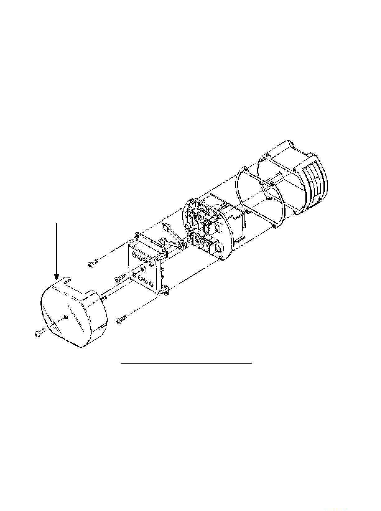
Figure 3-1 Exploded View of Model 502A . . . . . . . . . . . . . . . . . . . . . . . . . . . . . . . . . . . . . . . . 4
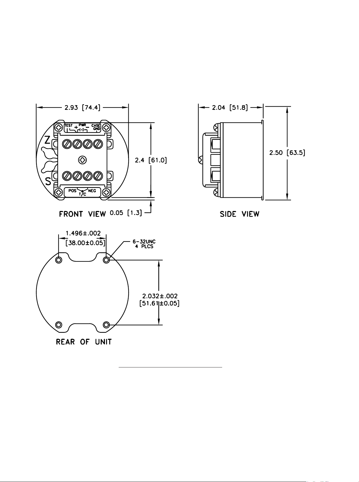
Figure 3-2 Case Dimensions . . . . . . . . . . . . . . . . . . . . . . . . . . . . . . . . . . . . . . . . . . . . . . . . . .5
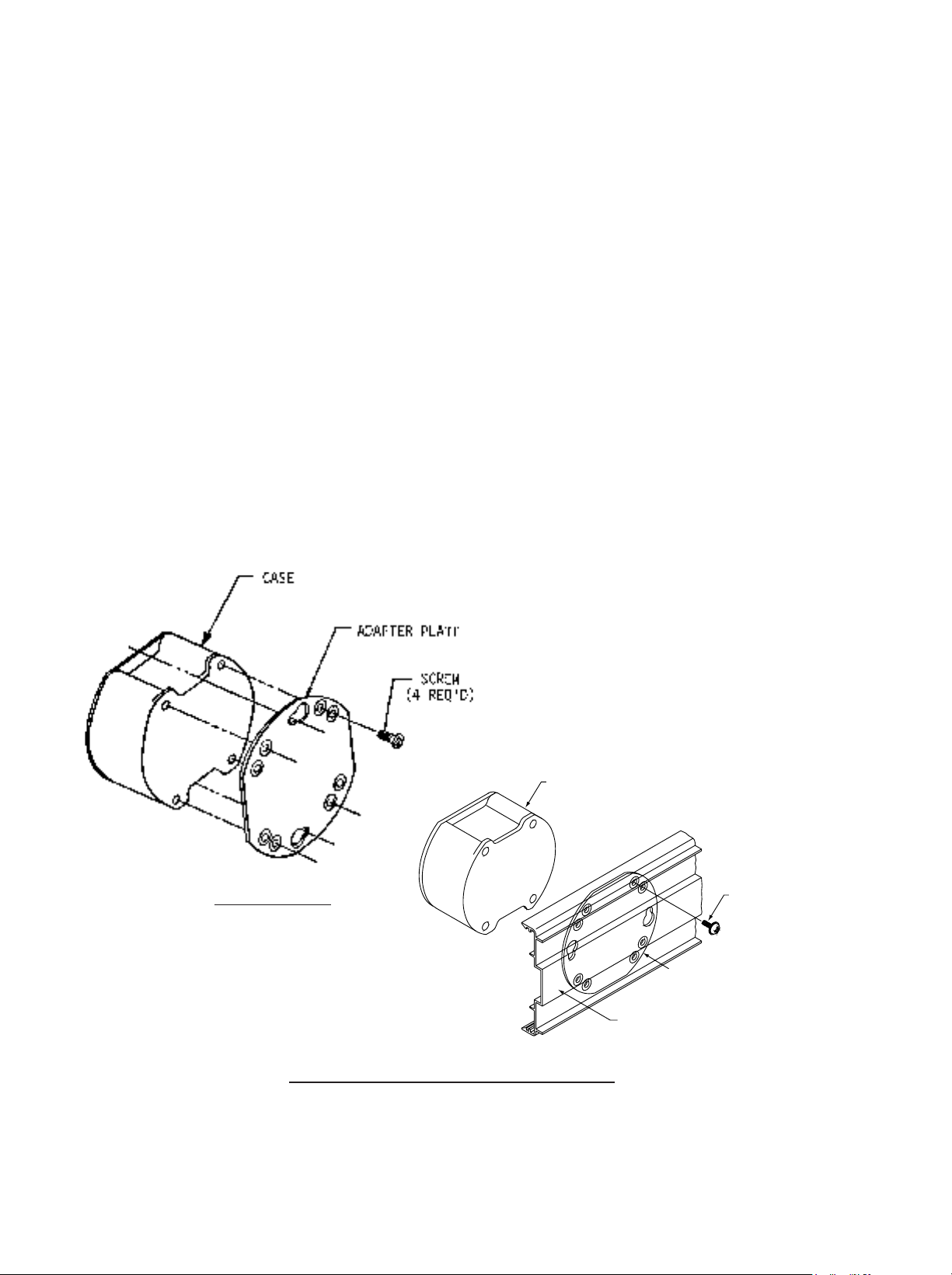
Figure 3-3 Bulkhead and Track Mounting . . . . . . . . . . . . . . . . . . . . . . . . . . . . . . . . . . . . . . . .6
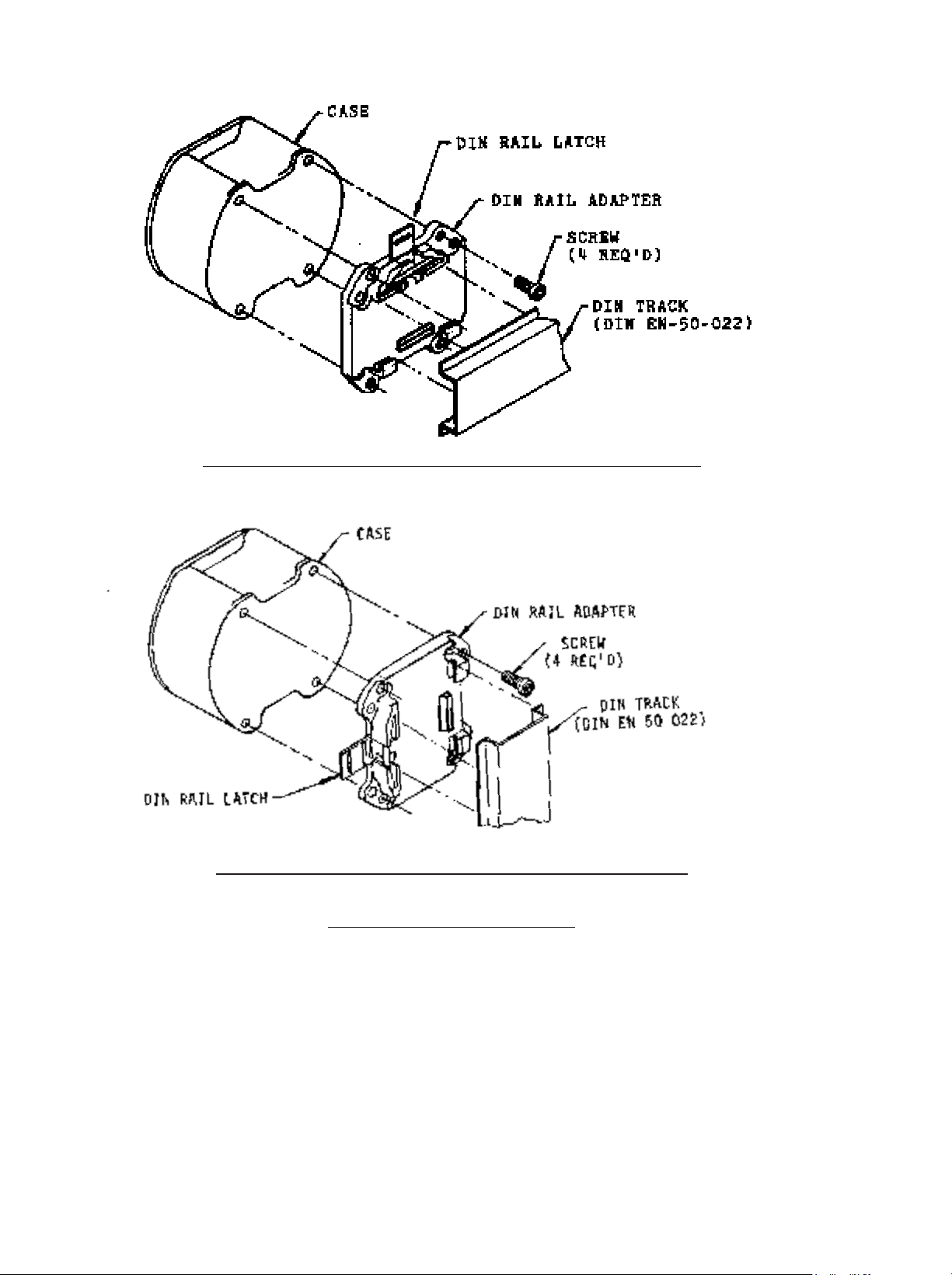
Figure 3-4 DIN Track Mounting . . . . . . . . . . . . . . . . . . . . . . . . . . . . . . . . . . . . . . . . . . . . . . . .7
Figure 3-5 Spring Retainer for Explosion-Proof Housing . . . . . . . . . . . . . . . . . . . . . . . . . . . .8
Figure 4-1 Power Input Connections . . . . . . . . . . . . . . . . . . . . . . . . . . . . . . . . . . . . . . . . . . . .9
Figure 5-1 Calibration Setup Using Ambient Temperature . . . . . . . . . . . . . . . . . . . . . . . . . . 10
Figure 5-2 Calibration Setup Using Ice-Point Cell . . . . . . . . . . . . . . . . . . . . . . . . . . . . . . . . .12
Figure 5-3 Jumper Diagram . . . . . . . . . . . . . . . . . . . . . . . . . . . . . . . . . . . . . . . . . . . . . . . . . 16
Figure 6-1 502A Preamp Block Diagram . . . . . . . . . . . . . . . . . . . . . . . . . . . . . . . . . . . . . . . . 17
Figure 6-2 502A Postamp Block Diagram . . . . . . . . . . . . . . . . . . . . . . . . . . . . . . . . . . . . . . . 17
Table 5-1 Type J Thermocouple Reference Table . . . . . . . . . . . . . . . . . . . . . . . . . . . . . . . . 10
Table 5-2 Celsius Temperature Ranges Obtained with Jumpers . . . . . . . . . . . . . . . . . . . . . 15
APPENDICES
Appendix A Transmitter Accuracy Factors . . . . . . . . . . . . . . . . . . . . . . . . . . . . . . . . . . . . . . . 18
i
Page 3

1
1.0 GENERAL INFORMATION
The 502A-J two-wire transmitter takes in millivolt signals generated by a type
J thermocouple, provides cold (reference) junction compensation, amplification, commonmode isolation, and controls the current drawn from a 9 to 50 V dc source to produce the
4 to 20 milliampere output signal.
Common-mode voltage between the input thermocouple and the output current circuit is
tested at 1500 V rms. As much as 750 ohms dropping resistance or 625 ohms in series
with a loop-powered indicator (Newport model 508A) may be used in the power leads of the
502A when the unit is energized from a 24 V dc source. This is because of the small
compliance voltage needed by the unit. Accidental overloads of over one minute by
120 V rms on either input or output leads do not damage the 502A.
1.1 ACCURACY AND STABILITY
The 502A-J has tailored resistance values installed to provide curvi- linear cold-junction
compensation matched to the NBS or IEC type J thermocouple table. Selected bridge
resistors in a temperature-sensing bridge also provide cancellation of Span temperature
effects. The unit is certified for accuracy from -40 to +85¡C (-40 to +185¡F) through
verification of high-ambient-temperature compensation points.
1.2 ADAPTABILITY/TURNDOWN
The Span of the 502A-J can be ranged anywhere from 100 to 800¡C by selection of one of
four jumper positions, with fine tuning provided by a multiturn, top-accessible potentiometer.
Sixteen Zero steps, also provided by 502A-J jumpers, allow placement of the 4.00 mA
output temperature anywhere from -50 to 700¡C, with fine tuning provided by another topaccessible, multiturn potentiometer. This 502A turndown capability exceeds that of any
other known transmitter.
1.3 ELECTRICAL ISOLATION
502A input (thermocouple and shield) and output (DC power) barrier strips accept wires up
to two millimeters in diameter (13 gauge), and are mechanically isolated from each other to
prevent input/output wiring contact during installation.
1.4 SHOCK RESISTANCE
Lightweight 502A circuit boards are formed into a rigid box structure and firmly soldered and
epoxied to the case top. The circuit-board box is doubly coated with RTV silicone for
environmental protection. When installed in the rugged, die-cast case, the 502A can
withstand the shock of a 6-foot drop onto a hard surface (although scarring of the case
and/or deformation of the plastic cover can occur).
1.5 WATERPROOF/RFI/THERMAL GRADIENT RESISTANT CASE
The 502A case is made from Zamac (zinc alloy), coated with polyurethane, and gasketed
with fluorosilicone. Fluorosilicone plugs protect the top-access Span and Zero
potentiometers. An optional opaque top cover shields the barrier strips from uneven
heating or cooling in exposed environments.
1.6 MOUNTING ADAPTABILITY
The small size of the 502A (less than 75 mm or 3 in. outside diameters) permits snap
mounting into the American 8TK2 relay track or wall mounting in confined areas. With a
bulkhead adapter, the 502A can be snap mounted into the larger American TR2/2TK relay
track or wall mounted by rotating the adapter 90 degrees. With the use of the rail clamp
adapter, the 502A may be mounted onto the narrow DIN EN-50-022 relay track. Using the
spring retainer option, the 502A can be mounted into explosion-proof housings.
Page 4

2
2.0 SPECIFICATIONS
2.1 INPUT
Configuration: Isolated input
Thermocouple type: J (ÒIron/ConstantanÓ)
Input impedance: 5 MOhm
Thermocouple break-detect current: 50 nA max
Burnout indication: Selectable up or down overscale
Thermocouple lead resistance: Up to 500 ohms for specified
performance
Normal mode rejection: 60 dB at 50/60 Hz with 100 mV input
Common mode voltage, input to case or output: 2100 V peak per high pot. test;
354 V peak per IEC spacing
Common mode rejection, input to case or output: 100 dB min from DC to 60 Hz
Overvoltage protection: 120 V ac max/1 min exposure
2.2 OUTPUT
Linear range: 4 to 20 mA dc
Compliance (supply-voltage): 9 to 50 V dc
Overvoltage protection: 120 V ac
Reverse polarity protection: 400 V peak
Common mode voltage, output to case or input: 2100 V peak per high pot. test;
354 V peak per IEC spacing
Common mode rejection,
output to case or input: 100 dB min from DC to 60 Hz
2.3 ACCURACY
Hysteresis and repeatability: Within ±0.2¡C ±0.1% of Span
Conformity, 100¡C Span: ±1¡C
Six month stability: Within ±0.2¡C ©+0.2% of 4 mA
temperature
Power supply effect Within ±0.005%/V
Ambient temperature effect for 50¡C change: Zero and conformity: Within ±0.5¡C
Span: Within 0.3%
Suppression: ±0.2% of 4 mA
temperature
Cold Juntion: Zero Error: ±0.04¡C/¡C Typical
Span Error: ±0.03¡C/¡C Typical
2.4 ENVIRONMENTAL
Operating temperature: -40 to 85¡C
Storage temperature: -55 to 125¡C
Humidity: To 100%
Vibration: 1.52 mm (.06 in) double amplitude,
10-80 Hz cycled
Shock: 55g, half-sine, 9-13 msec duration,
6' drop to hard surface
Watertight pressure limit: 35 kPa (5 psi)
Mounting position: Any
2.5 MECHANICAL
Case material: Zamac¼ (zinc alloy), polyurethane-
coated,
fluorosilicone-gasketed
Weight: 300 g (10 oz)
Diameter: 74 mm (2.9 in)
Height (including barriers): 52 mm (2.1 in)
Connections: #6 screws with wire clamps
Page 5

3
3.0 MECHANICAL ASSEMBLY AND INSTALLATION
3.1 UNPACKING AND INSPECTION
Your 502A-J was systematically inspected and tested, then carefully packed before
shipment. Unpack the instrument and inspect for shipping damage. If possible, remove the
casing and visually inspect the internal circuitry. Notify the freight carrier immediately if
damage exists.
Each package includes an assembled transmitter and an ownersÕ manual. If any items are
not according to your order, contact your local distributor or Newport Electronics.
3.2 SAFETY CONSIDERATIONS
As delivered from the factory/distributor, this instrument complies with required safety
regulations. To prevent electrical or fire hazard and to ensure safe operation, please follow
the guidelines below.
VISUAL INSPECTION: Do not attempt to operate the unit if damage is found.
MOUNTING: Observe the mounting instructions in the following pages, as applicable.
POWER VOLTAGE: Verify that the instrument is connected for the power voltage rating
that will be used (9-50 V dc). If not, make the required changes as indicated in Section 4.
POWER WIRING - This instrument has no power-on switch; it will be in operation as soon
as the power is connected.
SIGNAL WIRING - Do not make signal wiring connections or changes when power is on.
Make signal connections before power is applied. Disconnect the power before making
connection changes.
EXERCISE CAUTION - As with any electronic instrument, high voltage may exist when
attempting to install, calibrate, or remove parts of the transmitter.
Page 6
4
Figure 3-1 Exploded V
iew of Model 502A
Optional
Environmental
Cover
Page 7
5
Four tapped holes with #6-32
screw threads on the rear of
the case provide behind-thewall access for bulkhead
mounting; flanges on the rear
of the case snap into the
American 8TK2 rail for track
mounting.
Figure 3-2 502A Case Dimensions
Page 8
6
3.3 OPTIONAL ADAPTERS FOR MOUNTING
The following optional adapters provide various mounting choices:
a. Adapter plate for either front-screw-entry surface mount or
TR2/2TK relay track mount. See Figure 3-3.
b. Rail clamp for DIN EN-50-022 relay track mount. See Figure 3-4.
c. Spring retainer for explosion-proof housings that have internal
diameters of 76.4 to 88.9 mm (3.0 to 3.5 in.). See Figure 3-5.
For ordering purposes, the options are identified as follows:
Adapter plate MAT1
Rail Clamp MDT1
Spring Retainer for
Explosion-proof or
Waterproof housing MXS1
Explosion-proof/
Waterproof housing EPH (Includes MXS1)
3.4 SURFACE AND TR2/2TK RELAY TRACK MOUNTING PROCEDURE
BULKHEAD MTG
Figure 3-3 Bulkhead and Track Mounting
1. Position plate for desired application.
2. Use #6 hardware to mount plate to back of 502A case.
CASE
SCREW
(4 REQ'D)
ADAPTER PLATE
TR2/2TK
RELAY TRA CK
Page 9
7
3.5 DIN EN-50-022 RELAY TRACK MOUNTING PROCEDURE
DIN TRACK MOUNTING: SHOWN FOR HROIZONTAL TRACK
DIN TRACK MOUNTING: SHOWN FOR VERTICAL TRACK
Figure 3-4 DIN Track Mounting
1. Position adapter for desired track direction.
2. Use #6 screws to mount adapter to back of 502A case.
3. Snap 502A case assembly onto DIN rail.
Page 10
8
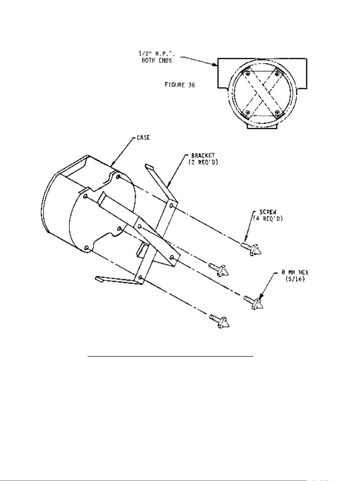
3.6 EXTERNAL EXPLOSION-PROOF HOUSING MOUNTING PROCEDURE
TOP VIEW OF EXPLOSION-PROOF
HOUSING. UNIT AND HOUSING
SHOWN FOR REFERENCE ONLY
Figure 3-5 Spring Retainer for Explosion-Proof Housing
1. Position spring retainer across back of 502A case.
2. Use wire protector feet (four provided with above option) to hold spring retainers in place.
3. Press 502A case assembly into explosion-proof housing.
Page 11
9
4.0 POWER AND SIGNAL INPUT CONNECTIONS
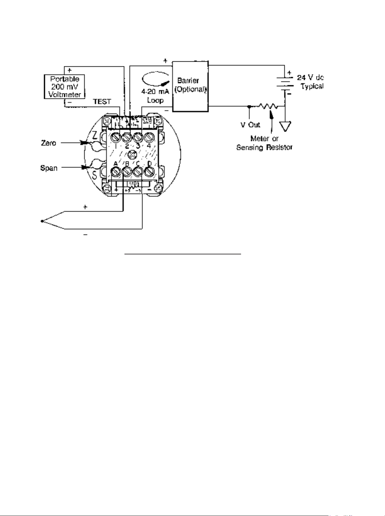
Figure 4-1 Power Input Connections
TEST, PWR +, and PWR - screws accept 2 mm (13 gauge) or lighter wire. CASE GND is
grounded to the case. Power input range is 9-50 V dc.
SCREW-TERMINAL PIN ASSIGNMENT
1 Test
2 + Power Output
3 - Power Output
4 Case Ground
A No Connection
B + Thermocouple Input
C - Thermocouple Input
D No Connection
Page 12
10
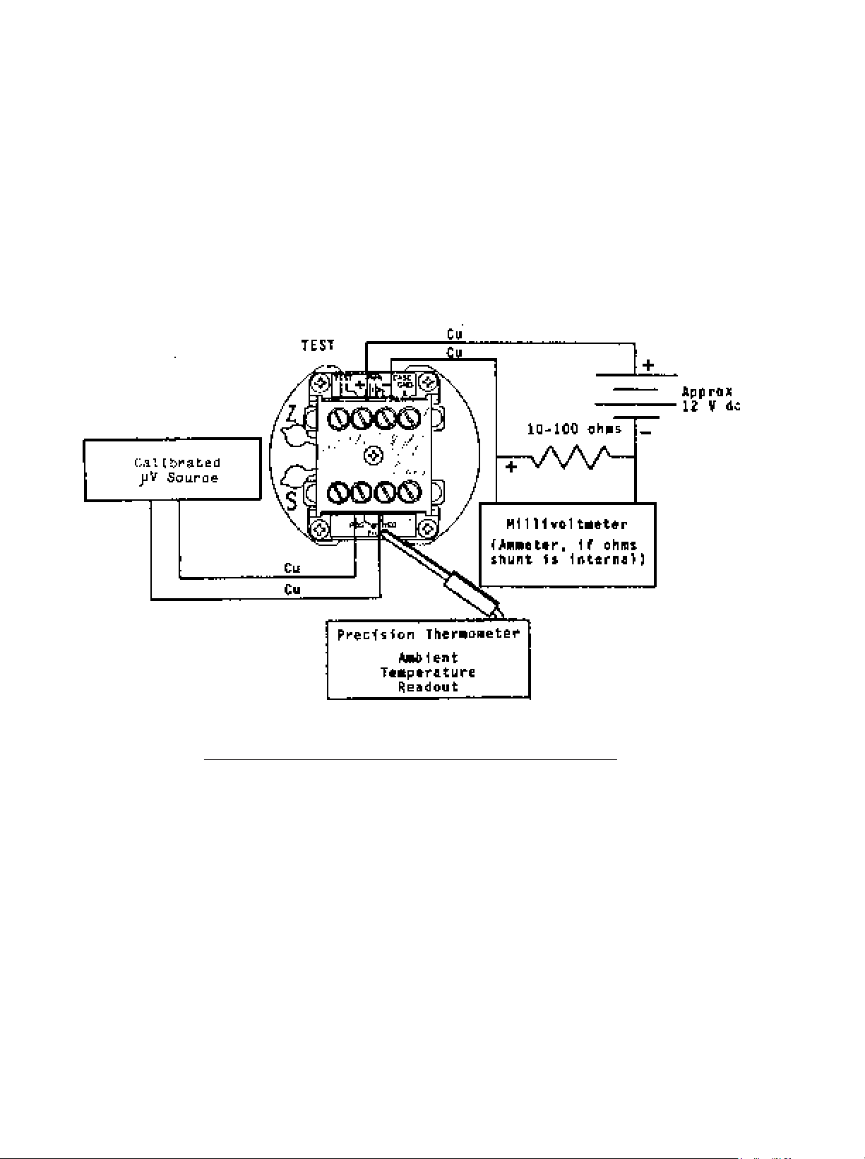
Figure 5-1 Calibration Setup Using
Ambient Temperature
5.2 CALIBRATION PROCEDURE, AMBIENT TEMPERATURE
1. Remove the outer four screws from the case top and lift out the electronics assembly
(attached to the case lid).
2. Pull out the two sealing plugs which cover the Span and Zero potentiometers (S pot
and Z pot). Adjust the S pot five turns clockwise (CW) from the fully counter-clockwise
(CCW) position.
NOTE: S pot and Z pot are both multi-turn pots; 25 complete turns in a CCW direction will
ensure that the pot is fully CCW.
3. Using Table 5-2, select the range which comes closest to your desired 4 and 20 mA
temperatures. Note which Zero and Span jumpers are called out in the table for the
range selected.
4. Turn the unit so that the jumper pin-forest is in view, and install the push-on jumpers on
the positions indicated (see Figure 5-3). Place the unused jumpers in storage positions.
5.0 CONFIGURATION
The 502A-J is normally delivered configured for 4/20 mA = 0/500¡C.
5.1 TOOLS AND EQUIPMENT
#1 Phillips screwdriver
3/32" flat blade screwdriver, VACO 17764 or equivalent
4 1/2 digit DVM (digital voltmeter)
10 or 100 ohms 1% resistor
Fixed or variable DC power supply or battery (range of 11-30 V dc) -3000 to 55000 uV source
Precision thermometer
KAYE 140 or equivalent 0¡C ice-point cell (Optional)
Page 13

11
5. Refer to Figure 5-1 and connect the transmitter to the power supply, microvolt source,
current shunt, and milliammeter. Place the temperature probe as close as possible to
the 502A-J input terminals. Better calibration stability is obtained if the electronic
assembly is configured while in the case.
6. Using Table 5-1, determine the microvolt level that the ambient (Room) temperature
represents. Subtract this from the microvolt level corresponding to the desired 4.00 mA
temperature, found in Table 5-1. This value is LO-IN.
7. Set the microvolt calibration source to LO-IN microvolts and adjust the Z pot until the
milliammeter reads 4.00 mA.
8. Using the previously determined microvolt level of the ambient (Room) temperature,
subtract this from the microvolt level corresponding to the desired 20.00 mA
temperature (Table 5-1). This value is HI-IN.
9. Set the microvolt calibration source to HI-IN microvolts and read the output current on
the milliammeter. This current level is designated Initial Top Current (ITC), normally
not equal to 20.00 mA.
10. Calculate the Corrected Top Current (CTC) with the following equation (generally this
will not equal 20.00 mA).
CTC = 16 . ITC / (ITC - 4 mA)
11. Adjust the S pot to obtain the Corrected Top Current on the milliammeter.
12. Now readjust the Z pot so that the milliammeter reads 20.00 mA.
13. Set the microvolt source to LO-IN microvolts. If the output current is not 4.00 mA,
repeat steps 7 through 12.
14. When calibration is complete, remove the transmitter from the setup and replace the
sealing plugs. Reinstall the unit in the case and ensure that the four screws are
tightened enough to compress but not flatten the gasket.
EXAMPLE:
Temperature Range = -58 to 662¡F or -50 to 350¡C *
* Conversion Formula for Fahrenheit to Celsius: (¡F - 32) x 5/9 = ¡C
Zero Jumper required, D (Table 5-2)
Span Jumper required, None (Table 5-2)
4.00 mA Output = -50¡C or -2431.0 uV (Table 5-1)
20.00 mA Output = 350¡C or 19088.5 uV (Table 5-1)
Ambient Temperature = 25¡C or 1277.0 uV (Table 5-1)
LO-IN = -2431.0 - 1277.0 = -3708.0 uV
HI-IN = 19088.5 - 1277.0 = 17811.5 uV
Calibration steps:
1. Adjust the S pot five turns CW from a fully CCW position.
2. Set microvolt source to -3708.0 uV.
3. Adjust the Z pot so that the milliammeter reads 4.00 mA.
4. Set microvolt source to 17811.5 uV.
5. Read the Initial Top Current.
6. Calculate the Corrected Top Current.
7. Adjust the S pot to obtain the Corrected Top Current.
8. Adjust the Z pot to obtain a 20.00 mA current reading.
9. Set microvolt source to -3708.0 uV.
10. If the output is not 4.00 mA, repeat steps 2 through 9.
For specific values not given
in T able 5-1, interpolation
may be used.
Page 14
12
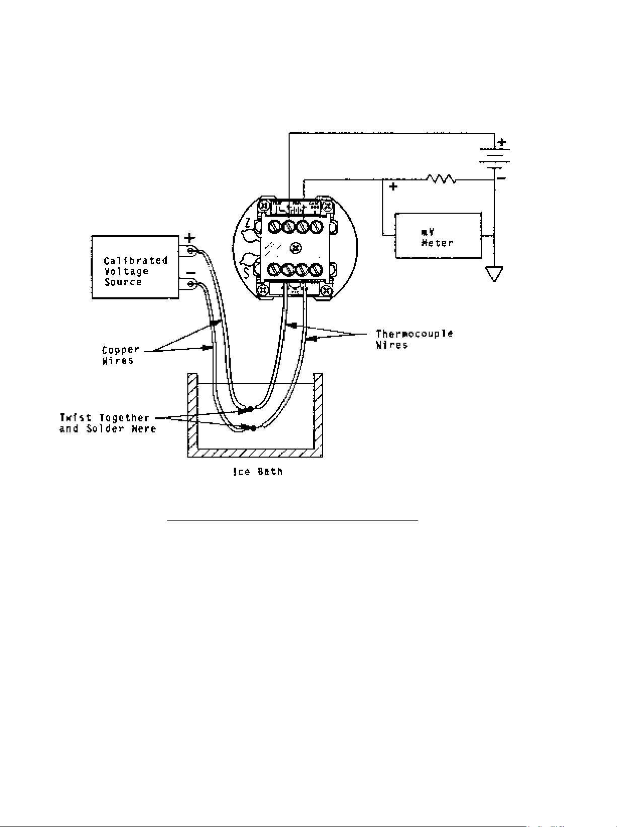
Figure 5-2 Calibration Setup Using Ice-Point Cell
5.3 CALIBRATION PROCEDURE, ICE-POINT CELL
1. Remove the outer four screws from the case top and lift out the electronics assembly
(attached to the case lid).
2. Pull out the two sealing plugs which cover the Span and Zero potentiometers (S pot
and Z pot). Adjust the S pot five turns clockwise (CW) from the fully counter-clockwise
(CCW) position.
NOTE: S pot and Z pot are both multi-turn pots; 25 turns in a CCW direction will ensure
that the pot is fully CCW.
3. Using Table 5-2, select the range which comes closest to your desired 4.00 and 20.00
mA temperatures. Note which Zero and Span jumpers are called out in the table for
the range selected.
4. Turn the unit so that the jumper pin-forest is in view and install the push-on jumpers
on the positions indicated (see Figure 5-3). Place the unused jumpers in storage
positions.
Page 15

13
5. Refer to Figure 5-1 and connect the transmitter to the power supply, microvolt source,
current shunt, and milliammeter. Ensure that the copper wires from the millivolt source
and the thermocouple wires from the 502A-J are soldered together and immersed in
the ice bath. Better calibration stability is obtained if the electronic assembly is
configured while in the case.
6. Using Table 5-1, determine the microvolt level corresponding to the desired 4 mA
temperature. This value is LO-IN.
7. Set the microvolt calibration source to LO-IN microvolts and adjust the Z pot until the
milliammeter reads 4.00 mA.
8. Determine the microvolt level corresponding to the desired 20.00 mA temperature.
This value is HI-IN.
9. Set the microvolt calibration source to HI-IN microvolts and read the output current on
the milliammeter. This current level is designated Initial Top Current (ITC), normally
not equal to 20.00 mA.
10. Calculate the Corrected Top Current (CTC) with the following equation (generally this
will not equal 20.00 mA).
CTC = 16 . ITC / (ITC - 4 mA)
11. Adjust the S pot to obtain the Corrected Top Current on the milliammeter.
12. Now readjust the Z pot so that the milliammeter reads 20.00 mA.
13. Set the microvolt source to LO-IN microvolts. If the output current is not 4.00 mA,
repeat steps 7 through 12.
14. When calibration is complete, remove the transmitter from the setup and replace the
sealing plugs. Reinstall the unit in the case and ensure that the four screws are
tightened enough to compress but not flatten the gasket.
Page 16

14
Type J Thermocouple Output Voltage, E, and Slope Sensitivity or Seebeck Coefficient, S, per
NBS Monograph 125 (Based on IPTS-68) or IEC publication 584-1, dated 1977.
TES
¡C uV uV/¡C
TES
¡C uV uV/¡C
TES
¡C uV uV/¡C
-50 -2431.0 46.615
-40 -1960.4 47.491
-30 -1481.4 48.301
-20 -994.6 49.049
-10 -500.6 49.738
0 0.0 50.373
10 506.7 50.956
11 557.7 51.012
12 608.7 51.067
13 659.8 51.122
14 711.0 51.176
15 762.2 51.229
16 813.4 51.283
17 864.7 51.335
18 916.1 51.388
19 967.5 51.440
20 1019.0 51.491
21 1070.5 51.542
22 1122.0 51.593
23 1173.7 51.643
24 1225.3 51.692
25 1277.0 51.741
26 1328.8 51.790
27 1380.6 51.838
28 1432.5 51.886
29 1484.4 51.934
30 1536.4 51.981
31 1588.4 52.027
32 1640.4 52.073
33 1692.5 52.119
34 1744.6 52.164
35 1796.8 52.209
36 1849.1 52.254
37 1901.3 52.298
38 1953.7 52.342
39 2006.0 52.385
40 2058.4 52.428
50 2584.8 52.835
60 3115.0 53.204
70 3648.7 53.538
80 4185.6 53.838
90 4725.4 54.107
100 5267.7 54.348
110 5812.3 54.560
120 6358.8 54.747
130 6907.1 54.910
140 7456.9 55.050
150 8008.1 55.170
160 8560.3 55.270
170 9113.4 55.351
180 9667.2 55.417
190 10221.7 55.466
200 10776.5 55.502
210 11331.7 55.525
220 11887.0 55.536
230 12442.4 55.537
240 12997.7 55.529
250 13552.9 55.514
260 14107.9 55.491
270 14662.7 55.463
280 15217.2 55.431
290 15771.3 55.396
300 16325.1 55.359
310 16878.5 55.321
320 17431.5 55.284
330 17984.2 55.248
340 18536.5 55.215
350 19088.5 55.186
360 19640.2 55.163
370 20191.8 55.145
380 20743.2 55.135
390 21294.5 55.133
400 21845.9 55.141
410 22397.4 55.160
420 22949.1 55.190
430 23501.2 55.233
440 24053.8 55.290
450 24607.1 55.361
460 25161.1 55.447
470 25716.1 55.549
480 26272.1 55.667
490 26829.5 55.804
500 27388.2 55.957
510 27948.7 56.129
520 28510.9 56.320
530 29075.1 56.529
540 29641.5 56.756
550 30210.3 57.003
560 30781.6 57.267
570 31355.7 57.549
580 31932.7 57.849
590 32512.7 58.165
600 33096.0 58.496
610 33682.7 58.841
620 34272.9 59.198
630 34866.7 59.567
640 35464.3 59.944
650 36065.6 60.328
660 36670.8 60.715
670 37279.9 61.103
680 37892.9 61.489
690 38509.7 61.869
700 39130.2 62.239
710 39754.4 62.594
720 40382.0 62.930
730 41012.9 63.241
740 41646.8 63.522
750 42283.2 63.767
760 42922.0 63.968
770 43563.0 64.265
780 44206.0 64.466
790 44852.0 64.580
800 45498.0 64.616
Table 5-1 Type J Thermocouple Reference Table
NOTE: Table above provides one degree steps from 10 to 40 ¡C to facilitate ambient-
temperature calibration method.
Page 17

15
JUMPERS USED POTENTIOMETER SETTINGS
ZPOT=CW ZPOT=CCW ZPOT=CCW ZPOT=CW
SPAN ZERO SPOT=.7CW SPOT=.7CW SPOT=CCW SPOT=CCW
Output Output Output Output
4 mA 20 mA 4 mA 20 mA 4 mA 20 mA 4 mA 20 mA
NONE -30 420 -25 760 130 760
D -50 365 20 470
C -45 410 75 520
C,D 10 460 125 570
B 65 510 180 620
NONE B,D 120 565 235 670
B,C 175 615 290 720
B,C,D 230 670 350 760
A 290 720
A,D 355 760
NONE -50 150 30 250 0 535 110 635
D -35 195 80 300 50 580 160 680
C 20 240 130 350 100 625 205 720
C,D 70 290 180 400 150 670 260 760
B 120 340 235 455 200 715
E B,D 175 395 290 510 250 760
B,C 230 450 345 565
B,C,D 285 505 405 620
A 345 565 470 675
A,D 410 625 530 735
A,C 475 680 595 760
A,C,D 540 740
A,B 610 760
NONE -50 75 55 180 -10 310 100 410
D -10 120 105 230 40 355 150 460
C 45 170 155 275 90 400 200 510
C,D 95 220 205 330 140 450 250 560
B 145 270 260 380 190 500 300 610
F B,D 200 325 315 435 245 555 355 660
B,C 255 380 370 495 300 605 415 710
B,C,D 310 435 430 555 355 660 475 760
A 370 495 490 610 415 710
A,D 435 555 555 670 475 760
A,C 495 615 620 730
A,C,D 565 680 685 760
A,B 630 740
A,B,D 695 760
NONE -45 35 70 140 -15 175 95 280
D 5 80 115 190 35 220 145 325
C 55 130 165 240 85 270 190 375
C,D 105 180 220 290 135 320 245 430
B 160 230 270 345 185 370 295 480
G B,D 210 285 325 400 235 420 350 535
B,C 265 340 385 455 290 475 410 590
B,C,D 325 395 445 515 350 535 470 645
A 385 515 505 575 470 650 590 760
A,D 445 515 565 635 470 650 590 760
A,C 510 580 630 695 535 705
A,C,D 575 645 695 760
A,B 640 705
A,B,D 710 760
Table 5-2 Celsius Temperature Ranges Obtained With Jumpers
Page 18
16
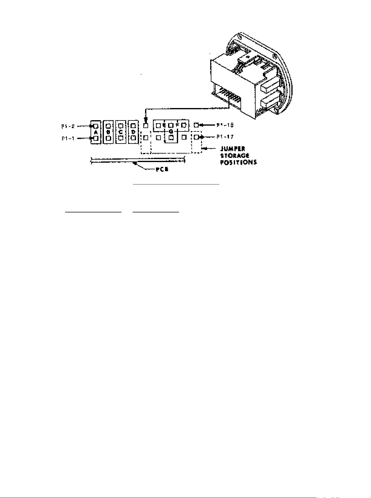
Figure 5-3 Jumper Diagram
5.4 PIN ASSIGNMENTS (Jumper Pin-forest P1)
Jumper Function P1 Pins Used
ÔAÕ Zero 1 and 2
ÔBÕ Zero 3 and 4
ÔCÕ Zero 5 and 6
ÔDÕ Zero 7 and 8
ÔEÕ Span 12 and 14
ÔFÕ Span 14 and 16
ÔGÕ Span 13 and 14
NOTE: P1 connector pins 9, 10, 11, 15, 17 and 18 are used solely for computerized
testing by the factory.
5.5 CALIBRATION FORMULA (Alternate to Using 4 mA to 20 mA Tables)
5.5.1 Calculation of ZEXTRA
When the SPAN pot is turned Clockwise it increases the output, decreasing the SPAN
required for full-scale output and adding ZEXTRA, which is used to set the Zero (4 mA
Temperature) jumpers.
ZEXTRA = (MAXSPAN - SPAN) /4
5.5.2 Zero Jumper Selection (Equation alternate to Table 5-2)
From none to four jumpers may be placed on the connector to suppress the ZERO
(temperature corresponding to 4 mA output). The equation is:
(ZERO+ZEXTRA) = 90 (8A+4B+2C+D) + 70 x ZPOT, ¡C
Where we put in a Ô1Õ for each jumper used (A,B,C,D) and the value of ZPOT ranges from
+1.0 to 0 to -1.0 as we turn it Clockwise.
NOTE: Store the unused jumpers between the bottom connector pins and the printed-
circuit board.
Page 19
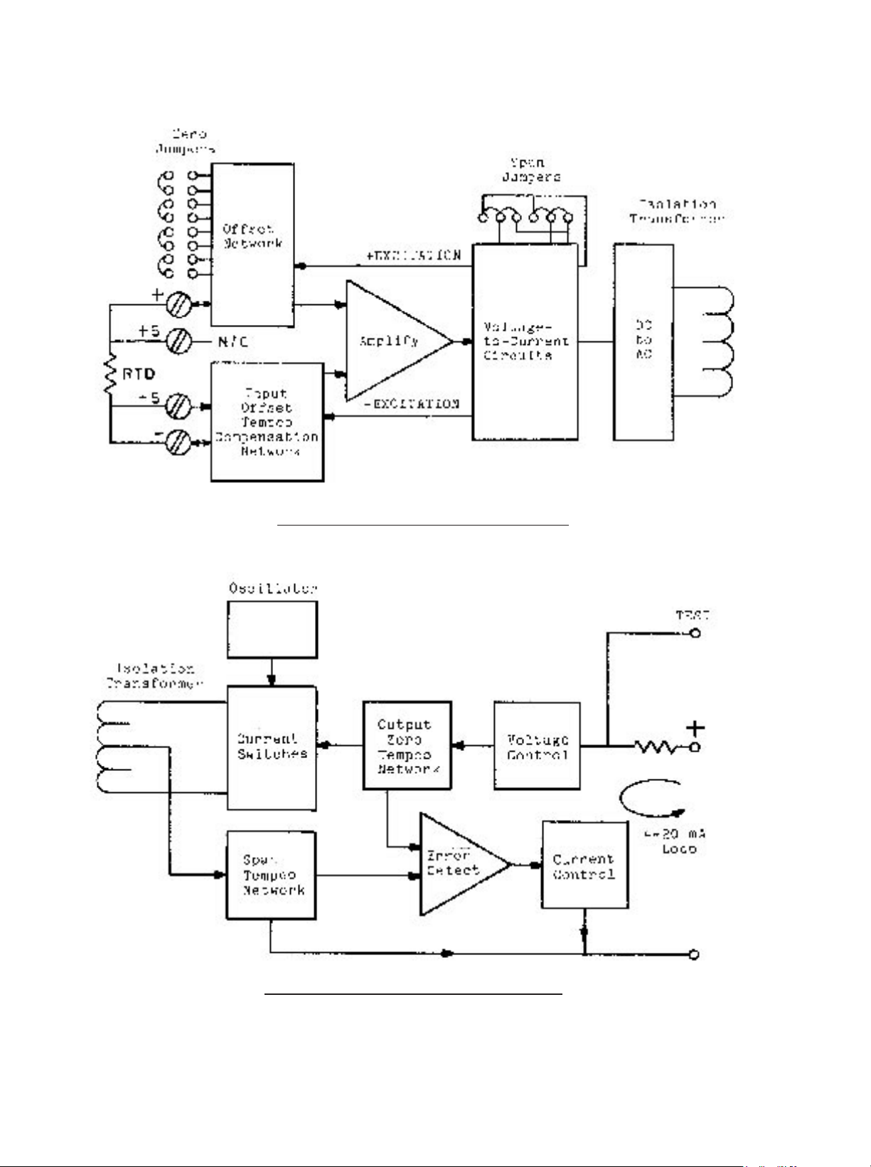
6.0 DRAWINGS
Figure 6-1 502A
Preamp Block Diagram
Figure 6-2 502A Postamp Block Diagram
17
Page 20

18
APPENDIX A
TRANSMITTER ACCURACY SPECIFICATIONS
The complex current-transmitter circuitry necessary to amplify, isolate, protect, and offset
weak input signals while consuming only small amounts of power can distort the signal in
many ways. Additional accuracy limitations occur in thermocouple transmitters, which
require precise cold-junction compensation and large Zero-suppression ranges in order to
obtain good sensitivity and linearity for high temperatures.
Many transmitter data sheets omit key accuracy factors and/or express performance in
percentage values without mentioning the full-scale value. Design limitations can be
disguised by such ÒspecsmanshipÓ; the 502A specifications, however, are detailed in order
to present the complete performance accuracy.
For a given thermocouple type, input errors are logically expressed in degrees (rather than
microvolts), and output errors are readily expressed in microamperes, since output is
current. Transmitter users are rarely interested in microamperes. Therefore, these output
current errors are translated back to input degrees as a percentage (or ppm) of the selected
Span.
Another fundamental division of errors is that of independence or dependence on Zero and
Reading. Resistor aging and tempco mismatch in the Zero and Voltage Reference circuits
will produce errors which increase with Zero suppression but which are independent of the
amount of Reading (value above the Zero). Resistor aging and tempco mismatch in the
amplifier gain (feedback) circuits will usually affect both Zero and Reading accuracy;
amplifier gain tempco variations are important to just the Reading stability. A complete error
specification needs a term proportional to Zero (suppression) and a term proportional to
Reading.
For thermocouple transmitters, the Cold-Junction Compensation (CJC) is never perfect,
even when factory-tailored over wide ambient excursions with curvilinear adjustments, as in
the 502A. This error component is readily stated as a percentage of the ambient
temperature excursion from the nominal temperature at which the Zero was set (assuming,
as in the 502A, that the Zero potentiometer has ample resolution on all Zero and Span
ranges). For transmitters with restricted turndown ratios (low Zero Suppression capability),
the tempco errors may be lumped into a single error term.
In addition to these three components of tempco (ambient temperature effects), there are
other possible errors, often referred to as Òhysteresis,Ó Òrepeatability,Ó Òdrift,Ó or ÒtimeÓ errors.
No statistically-significant errors of these types have yet been observed for the 502A, which
utilizes a solid-state, band-gap input voltage reference, matched-pair input PNP transistors,
integrated-circuit current source and imbalance control, and matched-tempco bridge
resistors. The 502A also provides a variable-tempco output adjustment (factory-set) which
eliminates many of the errors lumped in this category for other units. The 502A
specification, however, includes a 0.2¡C tolerance for the calibration accuracies.
Notes:
 Loading...