

Page 1
AVERAGING SERIES
TEMPERATURE TRANSMITTER
Installation & Operation Instructions
Phone: 1-888-967-5224
Website: workaci.com
GENERAL INFORMATION
The ACI Averaging Series sensors and transmitters
are continuous sensors that output 4-20 mA with an
optional voltage signal output of 1-5VDC or
2-10VDC signal to BAS or controller. All ACI/TT and
TTM temperature transmitters can be powered
from either an unregulated or regulated 8.5 to 32
VDC power supply.
MOUNTING INSTRUCTIONS
ACI’s Averaging Series Temperature Transmitter comes
with an averaging element and an enclosure for the
transmitter. The transmitter needs to be mounted in
environments with ambient temperatures between
-40 to 85 °C (-40 to 185 °F) - see SPECIFICATIONS (p. 4).
The averaging element operates between -40 to
135ºC (-40 to 275ºF).
For optimal temperature measurement, follow
these tips:
• Mount coil horizontal for vertical stratication.
• Mount coil vertical for horizontal stratication.
• The sensor must be spread evenly over the full
duct.
• The entire length of the sensor coil must be
installed completely inside the duct. Do not have
any part of the sensor exposed to exterior air.
• When installing the sensor near air-handling
units, place the sensor downstream from the fan
discharge. The stratied airstream will be more
uniform across the duct cross-section. If the air is
not well-mixed, the reading may be inaccurate.
• If UV Lights are installed in duct, do not use
Flexible Averaging. There is no UV protectant on
outer cable jacket. Copper averaging must be
used in this situation.
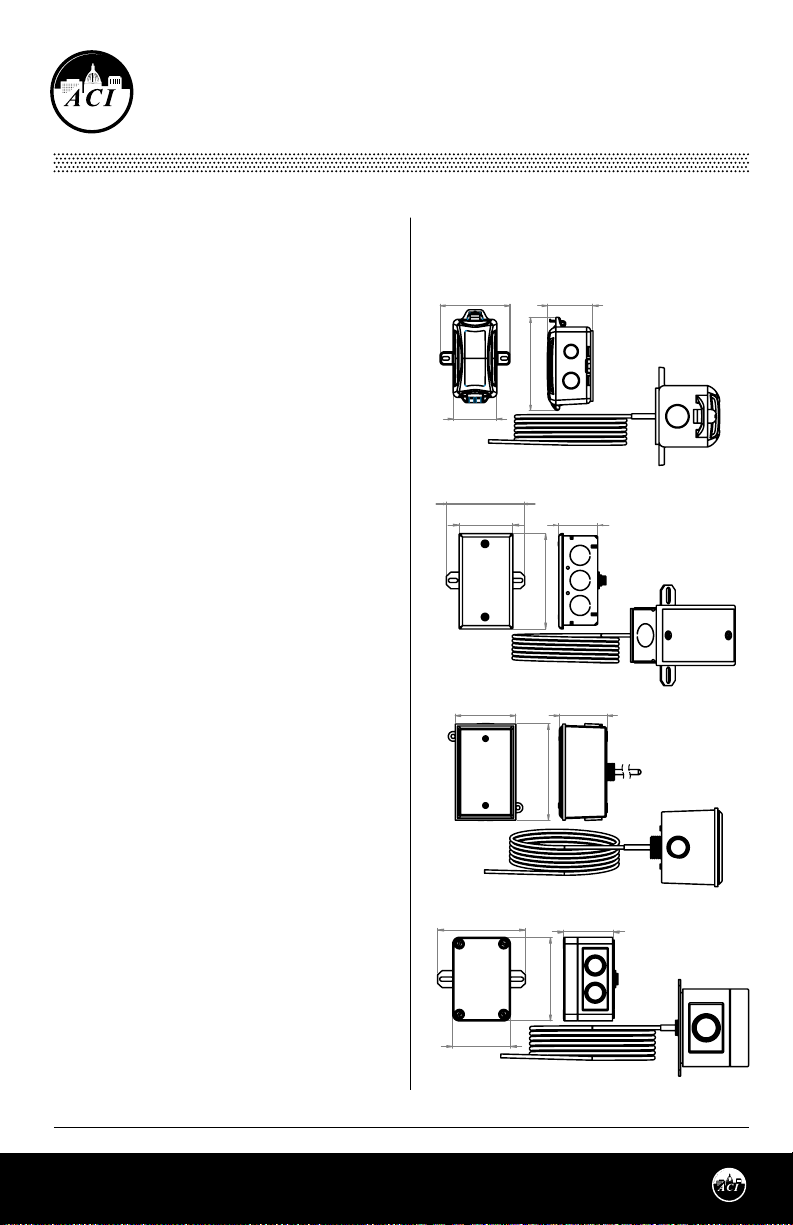
FIGURE 1: BULLET PROBE
DIMENSIONS
PLASTIC BOX (-PB)
3.60"
(91.44 mm)
2.25"
(57.15 mm)
GALVANIZED (-GD)
3.88"
(98.60 mm)
2.41"
(61.21 mm)
BELL BOX (-BB)
2.95"
(75.00 mm)
NEMA 4X (-4X)
3.88"
(98.60 mm)
(59.80 mm)
4.79"
(121.55 mm)
4.20"
(106.68 mm)
4.72"
(119.83 mm)
2.35"
1.78"
(45.18 mm)
2.34"
(59.38 mm)
(55.69 mm)
2.19"
TRANSMITTER MOUNTING
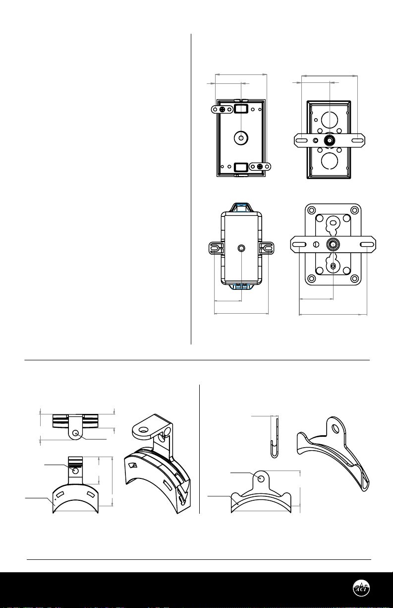
Drill pilot holes for the mounting screws. Use the
enclosure ange as a guide, or use the dimensions
listed in FIGURE 1 (right) and 2 (p. 2). Now fasten
and insert screws through the mounting holes in
the ange and tighten until the unit is held rmly to
the duct.
Automation Components, Inc.
2305 Pleasant View Road | Middleton, WI 53562
Phone: 1-888-967-5224 | Website: workaci.com
Page 1
2.55"
(64.77 mm)
3.70"
(93.980 mm)
Version: 2.0
I0000854
Page 2
MOUNTING INSTRUCTIONS
(Continued)
SENSOR MOUNTING
Drill a 3/8" (9.53 mm) hole in the duct. Gently
uncoil the copper tubing and insert the
averaging element through the hole until the
foam pad is tight to the duct. The sensor should
then be strung in a criss-cross pattern
throughout the duct using the mounting clips
provided - see FIGURE 4 (p. 3).
Use a pattern that covers the greatest surface
area of the duct to ensure that there is no
stratication. When bending the copper
tubing, be careful that you use a gradual bend
and that you DO NOT kink the copper tubing.
Bends should be a minimum of 2” (50.8 mm).
Each unit includes nylon wire ties and mounts
for mounting. Optional copper capillary (ACI
Item #
130525)
or universal plastic mounting
clips (ACI Item #
FIGURE 3 (below). Plastic mounting clips will
help insulate the copper sensing element
from the metal duct. The capillary clips help
avoid kinks when bending. When using
Flexible averaging, do not cover the
heatshrink that is located throughout the
sensor (sensing points).
128248
) can be ordered - see
FIGURE 2: MOUNTING DIMENSIONS
-BB ENCLOSURE -GD ENCLOSURE
3.18"
(80.77 mm)
1.59"
(40.39 mm)
-PB ENCLOSURE
1.51"
(38.25 mm)
3.01"
(76.51 mm)
3.08"
(78.23 mm)
1.54"
(39.12 mm)
-4X ENCLOSURE
1.54"
(39.12 mm)
3.08"
(78.23 mm)
FIGURE 3: MOUNTING CLIP DIMENSIONS
UNIVERSAL PLASTIC MOUNTING CLIP
(ACI #128248)
0.60”
1.13”
(28.58 mm)
Ø: 0.25”
(6.35 mm)
Ø: 1.14”
(28.83 mm)
Automation Components, Inc.
2305 Pleasant View Road | Middleton, WI 53562
Phone: 1-888-967-5224 | Website: workaci.com
2.00”
(50.80 mm)
Ø: 0.25”
(6.35 mm)
1.21”
(30.63 mm)
(15.18 mm)
2.49”
(63.13 mm)
Page 2
COPPER CAPILLARY CLIP
(ACI #130525)
(5.40 mm)
Ø: 1.38”
(35.09 mm)
Ø: 0.21”
0.24”
(6.16 mm)
2.05”
(51.94 mm)
(36.58 mm)
1.44”
Version: 2.0
I0000854
Page 3
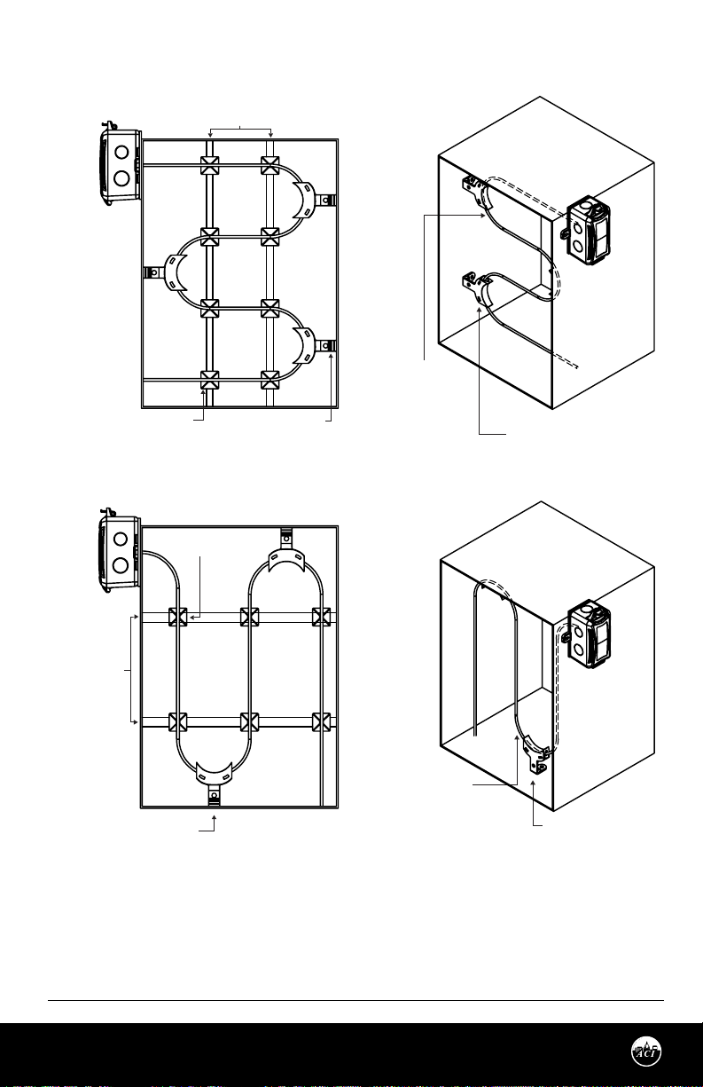
FIGURE 4: HORIZONTAL and VERTICAL COILING
HORIZONTAL COILING
HANGER STRIPS
MIN. BEND
RADIUS 2” (50.8 mm)
WIRE TIE MOUNT
VERTICAL COILING
HANGER STRIPS
OPTIONAL COPPER OR
PLASTIC CAPILLARY CLIP
OPTIONAL COPPER OR
PLASTIC CAPILLARY CLIP
WIRE TIE MOUNT
MIN. BEND
RADIUS 2” (50.8 mm)
OPTIONAL COPPER OR
PLASTIC CAPILLARY CLIP
OPTIONAL COPPER OR
PLASTIC CAPILLARY CLIP
Automation Components, Inc.
2305 Pleasant View Road | Middleton, WI 53562
Phone: 1-888-967-5224 | Website: workaci.com
Page 3
Version: 2.0
I0000854
Page 4
WIRING INSTRUCTIONS
PRECAUTIONS
• Transmitter is powered by 24 VDC only.
• Remove power before wiring. NEVER connect or disconnect wiring with power applied.
• When removing the shield from the sensor end, make sure to properly trim the shield to prevent any
chance of shorting.
• When using a shielded cable, ground the shield ONLY at the controller end. Grounding both ends can
cause a ground loop.
• If the 24 VDC power is shared with devices that have coils such as relays, solenoids, or other
inductors, each coil must have an MOV, DC Transorb, Transient Voltage Suppressor (ACI Part:
142583), or diode placed across the coil or inductor. The cathode, or banded side of the DC
Transorb or diode, connects to the positive side of the power supply. Without these snubbers,
coils produce very large voltage spikes when de-energizing that can cause malfunction or
destruction of electronic circuits.
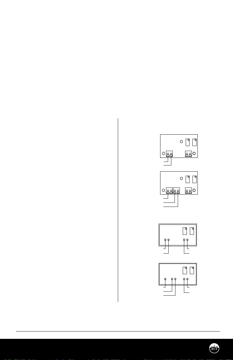
Open the cover of the enclosure. ACI recommends
16 to 26 AWG twisted pair wires or shielded cable
for all transmitters. Twisted pair may be used for
2-wire current output transmitters or 3-wire for
voltage output. Refer to FIGURE 4 (right) for wiring
diagrams. All wiring must comply with local and
National Electric Codes. All ACI TT and TTM temperature transmitters can be powered from either an
unregulated or regulated 8.5 to 32VDC power
supply. The TT and TTM DO NOT support an AC
input. All TT and TTM temperature transmitters are
reverse polarity protected. After wiring, attach the
cover to the enclosure.
The minimum voltage at the transmitter power
terminal is 8.5V after load resistor voltage drop.
• 249 Ω load resistor (1-5 VDC output) = 13.5 V min supply
voltage
• 499 Ω load resistor (2-10 VDC output) = 18.5 V min
supply voltage
Note: Adding extra wire length between the
sensor and transmitter board may aect accuracy.
Note: All RTD’s are supplied with (2) or (3) ying
lead wires. ACI’s transmitters are supplied with a 2
pole terminal block for RTD sensor connections.
When wiring a 3 wire RTD, connect the (2) common
wires (same color) together into the same terminal
block.
FORMULA FOR NUMBER OF TRANSMITTERS
Several transmitters may be powered from the same
supply as shown in FIGURE 5 (p. 4). Each transmitter
draws 25mA; refer to the following equation to obtain
the number of permissible transmitters: [#
Transmitters] = [Current] / (25 mA).
FIGURE 4: WIRING DIAGRAMS
STANDARD UNITS
ZERO
SPAN
Current Output
(4 to 20 mA)
4 to 20mA Output
Voltage Output
(1 to 5, 2 to 10VDC)
Voltage Output
(1 to 5, 2 to 10VDC)
POTTED UNITS
Current Output
(4 to 20 mA)
+VDC (Red Wire)
4 to 20mA Output
(White Wire)
Voltage Output
(1 to 5, 2 to 10VDC)
+VDC (Red Wire)
GND (White Wire)
Voltage Output
(Yellow Wire)
(1 to 5, 2 to 10VDC)
+VDC
+VDC
+
+
GND
RTD
-
SPANZERO
-
RTD
GND
VOUT
SPANZERO
RTD Wires
(100 Ohm RTD Brown Wires)
(1K Ohm RTD Black Wires)
SPAN
ZERO
RTD Wires
(100 Ohm RTD Brown Wires)
(1K Ohm RTD Black Wires)
Automation Components, Inc.
2305 Pleasant View Road | Middleton, WI 53562
Phone: 1-888-967-5224 | Website: workaci.com
Page 4
Version: 2.0
I0000854
Page 5
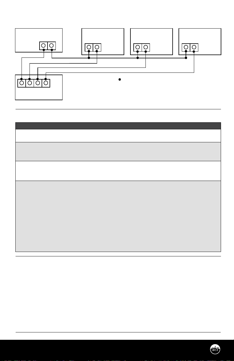
FIGURE 5: MULTIPLE TRANSMITTER CONNECTIONS
P
+ -
+ -
+ -
Temp.Transmitter #1
Temp.Transmitter #N
Temp.Transmitter #2
-
VDC
+
Controller
= Connections
I
I
I
ower Supply
Gnd In1 In2 In3
n1 = Controller Input #1
n2 = Controller Input #2
n3 = Controller Input #3
TROUBLESHOOTING
TEMPERATURE PROBLEM
No Reading
• No power to board - check voltage at power terminal - should be between +8.5 and 32 VDC.
Reading too Low
• R TD wires shorted. Disconnect wies from terminal block and check with ohmmeter. Reading should be close to 100 Ω or 1 KΩ.
• RTD Improper range of transmitter (too low). Check current or voltage - should be between 4-20 mA, 1-5 V, or 2-10 V.
Reading too High
• R TD opened. Disconnect sensor wires from terminal block and check with ohmmeter. Reading should be close to 100 Ω or 1 KΩ.
• Improper range of transmitter (too high). Check current or voltage - should be between 4-20 mA, 1-5 V, or 2-10 V.
Reading is Inaccurate
• Sensor check: Disconnect sensor wires from terminal block and check with ohmmeter. Compare the resistance reading
to the Temperature vs Resistance curves located on ACI’s website.
• Transmitter check: Make sure sensor wires are connected to terminal block. Determine that the proper output is being
transmitted based on predetermined span:
1. Go to ACI Website, Span to Output Page: http://www.workaci.com/content/span-output
2. Enter the low end of the span
3. Enter the high end of the span
4. Click on the output of the transmitter. This will generate a span to output chart.
5. Measure output of transmitter.
6. Compare measured output to calculated output
WARRANTY
The ACI Averaging Series sensors and transmitters are covered by ACI’s Five (5) Year Limited
Warranty, which is located in the front of ACI’S SENSORS & TRANSMITTERS CATALOG or can be found
on ACI’s website: www.workaci.com.
W.E.E.E. DIRECTIVE
At the end of their useful life the packaging and product should be disposed of via a suitable
recycling centre. Do not dispose of with household waste. Do not burn.
Automation Components, Inc.
2305 Pleasant View Road | Middleton, WI 53562
Phone: 1-888-967-5224 | Website: workaci.com
Page 5
Version: 2.0
I0000854
Page 6
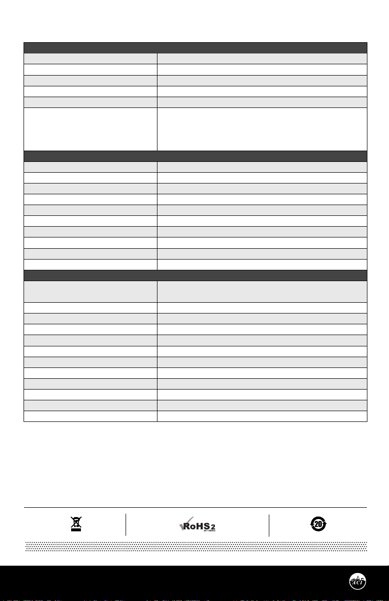
PRODUCT SPECIFICATIONS
SENSOR NON-SPECIFIC
Storage Temperature Range:
Operating Humidity Range:
Lead Length | Conductor Size:
Lead Wire Insulation | Wire Rating:
Conductor Material:
Enclosure Specications: (Operating
Temperature, Material, Flammability,
NEMA/IP Ratings):
SENSOR
Sensor Type | Sensor Curve | Sensing Points:
Sensor Output @ 0°C (32°F):
Sensor Accuracy:
Temperature Coecient:
Response Time (63% Step Change):
Sensor Operating Temperature Range:
Sensing Element Material | Sensor Diameter:
Probe Diameter | Probe Material:
Fitting Material | Flammability Rating:
Fitting Thread Size:
TRANSMITTER
Transmitter Supply Voltage |
Supply Current:
Maximum Load Resistance:
Output Signals:
Calibrated Accuracy | Linearity
2
Thermal Drift
:
1
:
Min./Max. Calibrated Temperature Spans:
TTM100/TTM1K Certication Points:
Warm Up Time | Warm Up Drift:
Transmitter Operating Temperature Range:
Transmitter Operating Humidity Range:
Connections | Wire Size:
Terminal Block Torque Rating:
Note: Transmitter’s calibrated at 71ºF (22ºC) nominal | Note: Thermal Drift is referenced to 71ºF (22ºC) nominal calibration temperature
-40 to 80 °C (-40 to 176 °F)
5 to 90% RH, non-condensing
12” (30.5 cm) | 22 AWG (0.65mm)
Etched Teon (PTFE) Colored Leads | Mil Spec 16878/4 Type E
Silver Plated Copper
“-GD” : Galvanized Steel, -40 to 115 °C (-40 to 239 °F), NEMA 1 (IP10)
“-PB” : ABS Plastic, -30 to 90 °C (-22 to 194 °F), UL94-HB, Plenum Rated
“-BB” : Aluminum, -40 to 115 °C (-40 to 239 °F), NEMA 3R (IP 14)
“-4X” : Polystyrene Plastic, -40 to 70 °C (-40 to 158 °F), UL94-V2, NEMA 4X (IP 66)
Platinum RTD | PTC (Positive Temperature Coecient) | Continuous
1000 Ohms nominal
+/- 0.1% @ 0 °C (32 °F) | +/- 0.25% @ 21 °C (70 °F) | +/- 1.0% @ 130 °C (266 °F)
3850 ppm / ºC
15 Seconds nominal
-40 to 135ºC (-40 to 275ºF)
Copper | 0.210” (5.34mm) nominal
0.250” (6.35mm) | 304 Stainless Steel
Polyamide 66 (High Performance Nylon 66) | UL94-HB
1/8”-27 NPSM
+8.5 to 32 VDC (Reverse Polarity Protected) | 25 mA minimum
250 Load: +13.5 to 32 VDC | 500 Load: +18.5 to 32 VDC
(Terminal Voltage - 8.5 V) | 0.020 A
Current: 4-20 mA (2-Wire) | Voltage: 1-5 VDC or 2-10 VDC (3-Wires)
T. Spans < 500 °F (260 °C): +/- 0.2%
T. Spans < 100 °F (38 °C): +/- 0.04%/ °F | T. Spans > 100 °F (38 °C): +/- 0.02%
Min. T. Span: 50 °F (28 °C) | Max T. Span: 400 °F (204 °C)
3 Pt. NIST: 20, 50, & 80% of span | 5 Pt. NIST: 20, 35, 50, 65, & 80% of span
10 Minutes | +/- 0.1%
-40 to 185 °F (-40 to 85 °C)
0 to 90%, non-condensing
Screw Terminal Blocks | 16 AWG (1.31 mm
2
) to 26 AWG (0.129 mm2)
0.37 ft-lb (0.5 Nm ) nominal
Automation Components, Inc.
2305 Pleasant View Road | Middleton, WI 53562
Phone: 1-888-967-5224 | Website: workaci.com
Page 6
Version: 2.0
I0000854
 Loading...