

Page 1
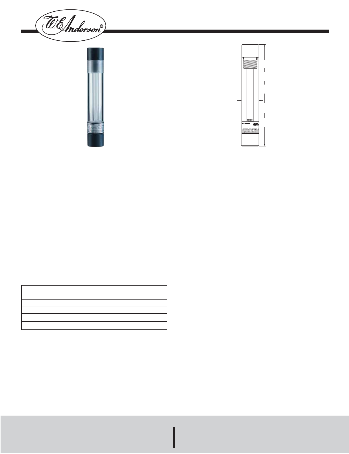
Series TLI Tank Level Indicator
9 TLI-0
[228.60]
15 TLI-1
[381.00]
27 TLI-2
[685.80]
39 TLI-3
[990.60]
51 TLI-4
[1295.40]
1-1/2
[38.10]
Specifications - Installation and Operating Instructions
Bulletin E-83
Series TLI Tank Level Indicators provides a visual indication of
the height of liquid contained in a tank. The 1/2-foot unit can also
be used as a sight flow tube when mounting in a pipeline. The TLI
series utilizes a double wall construction to indicate the level of
corrosive or ultra-pure liquids. This series should not be used with
hydrofluoric acid or sodium hydroxide, as they will etch the
Borosilicate tube. The TLI series is available with PVC,
Polypropylene, or PTFE fittings and 1/2 or 3/4 NPT threads.
PHYSICAL DATA
Temperature Limit: 140°F (60°C) PVC,
210°F (100°C) PTFE, 185°F (85°C) Polypropylene.
Operating Pressure: 100 psi.
Continuous operation 180°F (82°C).
Piping Connections: 1/2 or 3/4 NPT.
Wetted Materials: Borosilicate Glass, Flouroelastomer O-rings,
PVC, Polypropylene or PTFE Fittings. Non-wetted Acrylic.
Fluoroelastomer seals are standard. All units are hydrostatically
tested to 400 psi.
INSTALLATION
The Tank Level Indicators are easily installed in a piping system.
Polypropylene note: Due to the unstable nature of virgin
Polyporylene under pressure, leakage could occur at almost any
condition. If leakage occurs, the threaded connection should be
properly fillet welded.
The device should be installed vertically when used as level indi-
cators. The Indicators can be used as sight flow tubes and mount-
ing horizontally if desired. It is recommended that connections be
made to plastic fittings. Male threads should be wrapped with pipe
thread sealant tape tape or other acceptable pipe sealant. Hand-
tight plus one-quarter turn is usually adequate for assembly. Do
not use pipe wrenches. Direct connection to metal pipe could cut
into the plastic and result in future rupture. It is recommended that
Stocked Models:
Model
Number
TLI-0-1
TLI-2-1
TLI-3-1
the indicators be installed to the tank with union ball valves. This
will allow easy removal from the piping system for cleaning or
inspection. When installed on tank heights greater than 4 feet, a
staggered mounting arrangement is recommended to provide an
uninterrupted view of the liquid. Do not connect the indicators
together with pipe nipples. Two indicators may be used together
as a high/low viewing area, as long as the section of pipe between
the two is supported.
TLI-4-1
Note: For 3/4 NPT fittings, change the last digit of the model number to 2.
OPTIONS
-AT Aluminum Tag
-P Polypropylene Fittings
-T Teflon Fittings
©Copyright 2007 Dwyer Instruments, Inc. Printed in U.S.A. 3/07 FR#83-443160-00 Rev.2
MAINTENANCE
When properly installed the Tank Level Indicators require little or no
attention. Periodic maintenance checks should be preformed to
inspect the outer tube for damage due to outside sources, which
could affect the structure integrity of the Indicator. Also the inner
tube should be inspected to determine if cleaning is needed. The
unit should only be cleaned with products that are compatible with
all construction materials, and also with the process being moni-
tored.
DWYER INSTRUMENTS, INC.
Phone: 219/879-8000 www.dwyer-inst.com
Lit-By Fax: 888/891-4963
 Loading...