

Page 1
ROOM SERIES
Installation & Operation Instructions
PCB: SENSOR 2
Phone: 1-888-967-5224
Website: workaci.com
PRECAUTIONS
• DO NOT RUN THE WIRING IN ANY CONDUIT
WITH LINE VOLTAGE (24/120/230 VAC).
MOUNTING INSTRUCTIONS
Separate the cover from the base. Attach the base
directly to the wall or to a standard 2” x 4” junction
box using the (2) #6-32 x 1” screws provided.
Take care when mounting. Check local code for
mounting height requirements. Typical mounting
heights are 48-60” (1.2-1.5 m) o the ground and at
least 1.5’ (0.5 m) from the adjacent wall. The sensor
should be mounted in an area where air circulation is
well mixed and not blocked by obstructions.
*Reference FIGURE 2 (next page)
For optimal temperature measurement, follow
these tips:
• Do not install on external walls.
• Avoid air registers, diusers, vents, and windows.
• Avoid conned areas such as shelves, closed
cabinets, closets, and behind curtains.
• Eliminate and seal all wall and conduit penetrations.
Air migration from wall cavities may alter
temperature readings.
• A thermally-insulated backing should be used when
tting to solid walls (concrete, steel, etc.). ACI part:
A/ROOM-FOAM-PAD
*Reference FIGURE 3 (next page)
• Do not install near heat sources, eg: lamps,
radiators, direct sunlight, copiers, chimney
walls, walls concealing hot-water pipes.
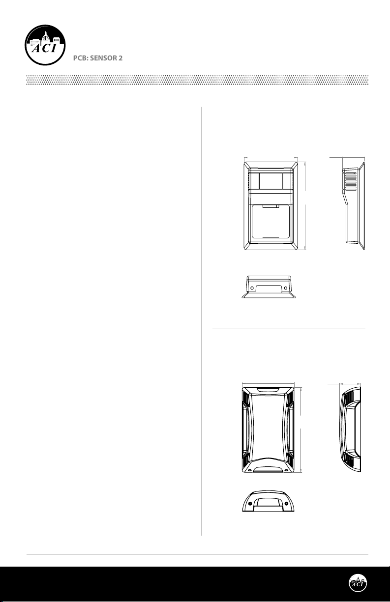
FIGURE 1: ROOM DIMENSIONS
ROOM, VERSION 1
[R]
2.75"
(69.85 mm)
FRONT
BOTTOM
ROOM, VERSION 2
[R2]
2.75"
(69.85 mm)
FRONT
1.12"
(28.55 mm)
4.50"
(114.30 mm)
1.12"
(28.55 mm)
4.50"
(114.30 mm)
RIGHT
RIGHT
Refer to the wiring instructions (p. 2) to make
necessary connections. After wiring, attach the
cover to the base by snapping the top of the cover
on rst and then the bottom. Tighten the cover
down, using the (2) 1/16” Allen screws located in
the bottom of the housing. A 1/16” Hex driver is
needed to secure the cover to the base.
Automation Components, Inc.
2305 Pleasant View Road | Middleton, WI 53562
Phone: 1-888-967-5224 | Website: workaci.com
BOTTOM
Page 1
Version: 7.0
I0000126
Page 2
WIRING INSTRUCTIONS
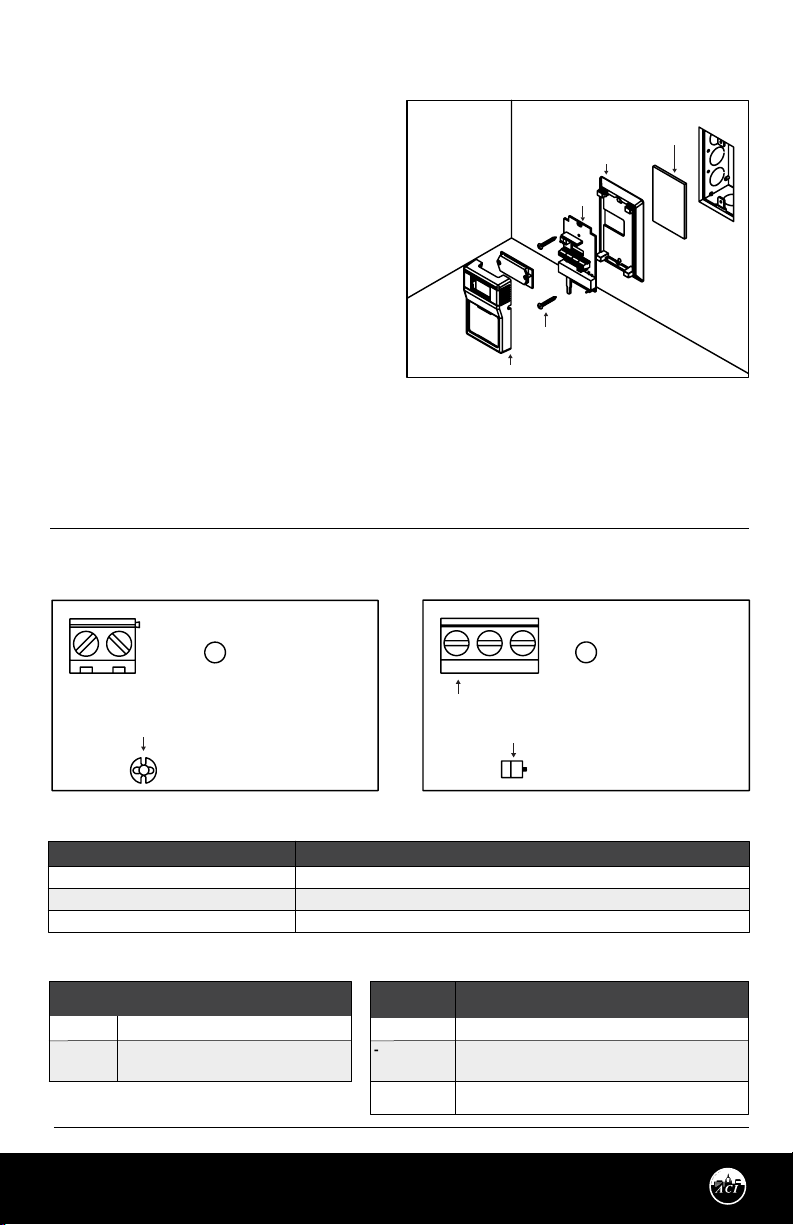
FIGURE 2: MOUNTING
ACI recommends 16 to 26 AWG twisted pair
wires or shielded cable for all sensors. Signal
wiring must be run separate from low and
high voltage wires (24/120/230 VAC). All ACI
thermistors and RTD temperature sensors are
both non-polarity and non-position sensitive.
OPTIONAL INSULATING
BACKPLATE
CIRCUIT BOARD
GASKET
All 592’s and 592-10K’s are polarity sensitive.
All thermistor type room units are supplied
with a two-pole terminal block and all RTD’s
can be supplied with either a two or
three-pole terminal block. All 592’s are
#6-32 x 1”
MOUNTING SCREWS
supplied with a two-pole terminal block and
all 592-10K’s are supplied with a three-pole
COVER
terminal block. The number of wires needed
depends on the application. All wiring must comply with all local and National Electric Codes.
Note: When using a shielded cable, be sure to connect only (1) end of the shield to ground at the
controller. Connecting both ends of the shield to ground may cause a ground loop. When removing the
shield from the sensor end, make sure to properly trim the shield to prevent any chance of shorting.
FIGURE 3: SENSOR 2 PCBs
2-Wire 3-Wire (592, RTDs)
-+
-+
3W
THERMISTOR
TABLE 1: THERMISTOR/RTD SENSOR CONNECTIONS
TERMINAL BLOCKS
+
-
3W
TABLE 2: 592 SENSOR CONNECTIONS
TERMINAL
BLOCK
+
-
Automation Components, Inc.
2305 Pleasant View Road | Middleton, WI 53562
Phone: 1-888-967-5224 | Website: workaci.com
CONNECTIONS
+15 VDC Input
Sensor Output signal(uA) to controller
analog input
CONNECTIONS
Temperature sensor signal to controller analog input
Temperature sensor signal common to controller analog input
Temperature sensor signal common to controller
TABLE 3: 592-10K SENSOR CONNECTIONS
TERMINAL
BLOCKS
+
-
3W
TERMINAL BLOCKS
RTD
(RTD 3W Only) analog input
CONNECTIONS
+15 VDC Input
Sensor Output signal(VDC) to controller analog
input
Power Supply Common/Ground
Page 2
Version: 7.0
I0000126
Page 3
TROUBLESHOOTING
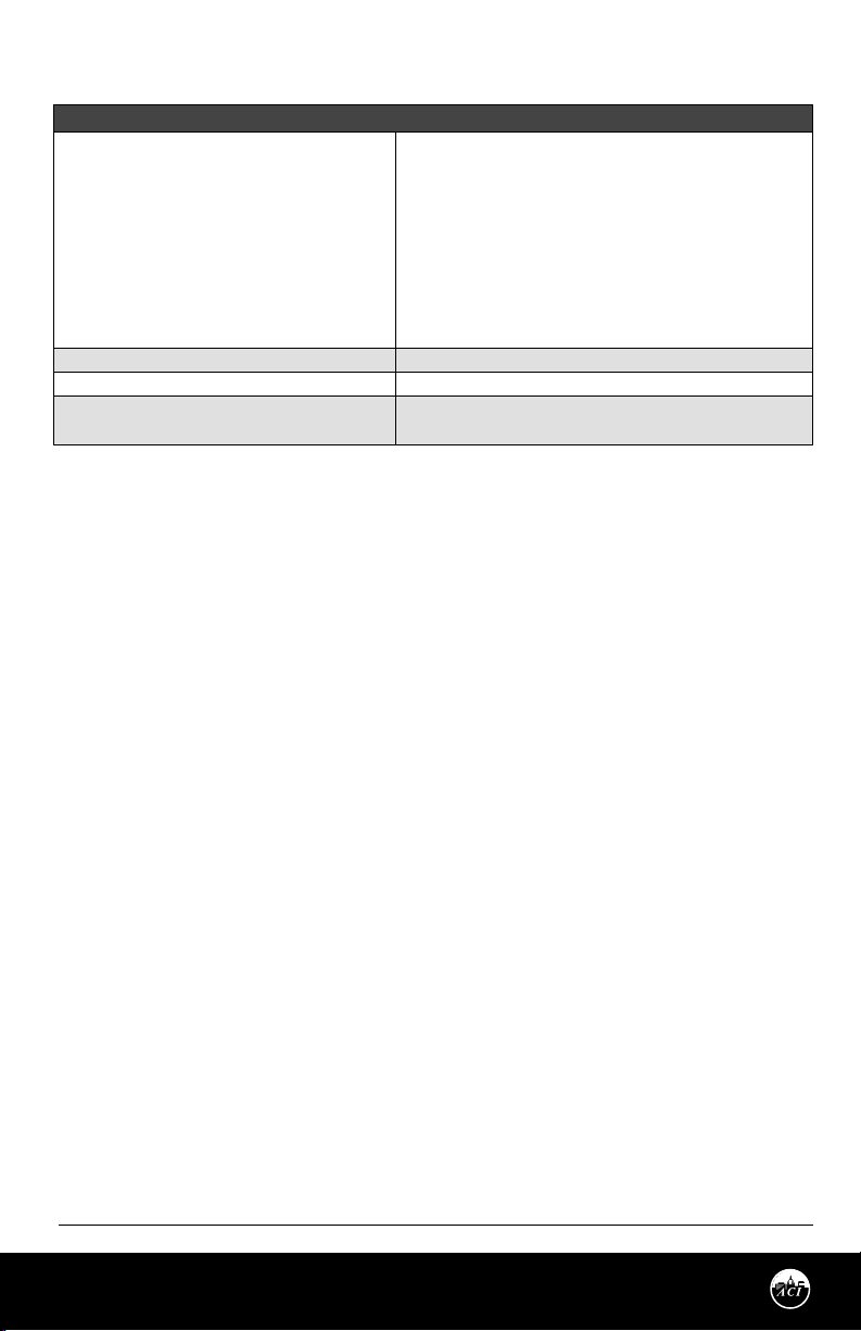
PROBLEM
Sensor reading is incorrect
Sensor reads innity/very high resistance
Sensor reads low resistance
Erratic readings
SOLUTION(S)
• Verify sensor wiring to controller is not damaged and has continuity.
• Verify sensor or wires are not shorted together.
• Verify controller is setup for correct sensor curve.
• Disconnect wires from sensor terminal block, tighten terminal block
screws down, and take a resistance (ohm) reading with a multimeter.
• Compare the resistance reading to the Temperature Vs Resistance
Curves online: http://www.workaci.com/content/thermistor-curves-0
• Verify proper mounting location to conrm no external factors are
aecting reading.
• Sensor or wires are open.
• Sensor or wires are shorted together.
• Condensation on PCB board
• Bad wire connections.
W.E.E.E. DIRECTIVE
At the end of their useful life the packaging and product should be disposed of via a suitable recycling
centre. Do not dispose of with household waste. Do not burn.
WARRANTY
The ACI Room Series temperature sensors are covered by ACI’s Five (5) Year Limited Warranty, which is located in
the front of ACI’S SENSORS & TRANSMITTERS CATALOG or can be found on ACI’s website: www.workaci.com.
Automation Components, Inc.
2305 Pleasant View Road | Middleton, WI 53562
Phone: 1-888-967-5224 | Website: workaci.com
Page 3
Version: 7.0
I0000126
Page 4
PRODUCT SPECIFICATIONS
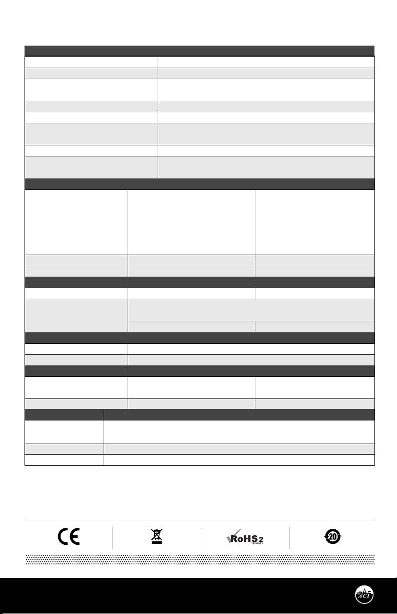
SENSOR NON-SPECIFIC INFORMATION
Number Temperature Sensing Points:
Housing Screw Size / Drive Size:
Override Option:
Operating | Storage Temperature Range:
Operating Humidity Range:
Connections / Wire Size:
Terminal Block Torque Rating:
Enclosure Material | Color:
THERMISTOR
Sensor Output @ 25 °C (77 °F):
Accuracy @ 0-70 °C (32 - 158 °F):
PLATINUM
Sensor Output @ 0 °C (32 °F):
Accuracy:
BALCO
Sensor Output @ 21.1 °C (70 °F):
Accuracy:
NICKEL
Sensor Output @ 21.1 °C (70 °F):
Accuracy:
592/592-10K
Sensor Output:
Accuracy @ 77°F (25°C):
Oset:
A/1.8K: 1.8 KΩ nominal
A/3K: 3 KΩ nominal
A/AN (Type III): 10 KΩ nominal
A/AN-BC: 5.238 KΩ nominal
A/CP (Type II): 10 KΩ nominal
A/50K: 50KΩ nominal
A/1.8K Series: +/- 0.5 °C @ 25 °C (77 °F)
and (+/-1.0 °C) (+/-1.8 °F)
A/100: 100 Ω nominal
+/- 0.06% Class A (Tolerance Formula: +/- °C = (0.15 °C + (0.002 * |t|))
where |t| is the absolute value of Temperature above or below 0 °C in °C)
@ 0 °C (32 °F): +/- 0.15 °C (+/- 0.27 °F)
1 KΩ nominal
@ 21.1 °C (70 °F): +/- 1%
1 KΩ nominal
@ 0 °C (32 °F): +/- 0.4 °C (+/- 0.72 °F)
@ 21.1 °C (70 °F): +/- 0.17 °C (+/- 0.34 °F)
A/592: 248 to 378 uA
A/592-10K: 2.48 to 3.78 VDC
+/- 1.26 °F (+/- 0.70 °C)
+/- 4 °F max (+/- 2.2 °C max)
One
1/16” Allen screws (2 qty) / 1/16” Hex Driver
Short Thermistor (Default); Field (Jumper) Selectable
“Dry Contact” Closure (Separate Input);
1.5 to 50 °C (35 to 122 °F) | -40 to 65 °C (-40 to 149 °F)
10 to 95% RH, non-condensing
Screw Terminal Blocks (Non-Polarity Sensitive)
16 (1.31 mm²) to 26 AWG (0.129 mm²)
0.5 Nm (Minimum); 0.6 Nm (Maximum)
“R2” Enclosure: ABS Plastic | White, UL94-HB
“R” Enclosure: ABS Plastic | Beige UL94-HB
A/CSI: 10 KΩ nominal
A/10KS: 10 KΩ nominal
A/10K-E1: 10 KΩ nominal
A/20K: 20 KΩ nominal
A/100KS: 100 KΩ nominal
A/10K-E1 Series: +/- 0.3 °C (+/- 0.54 °F)
All Else: +/- 0.2 °C (+/- 0.36 °F)
A/1K: 1 KΩ nominal
@ 50 °C (122 °F): +/- 0.25 °C (+/- 0.45 °F)
@ 54.4 °C (130 °F): +/- 0.56 °C (+/- 1. 00°F)
Automation Components, Inc.
2305 Pleasant View Road | Middleton, WI 53562
Phone: 1-888-967-5224 | Website: workaci.com
Page 4
Version: 7.0
I0000126
 Loading...