

Page 1
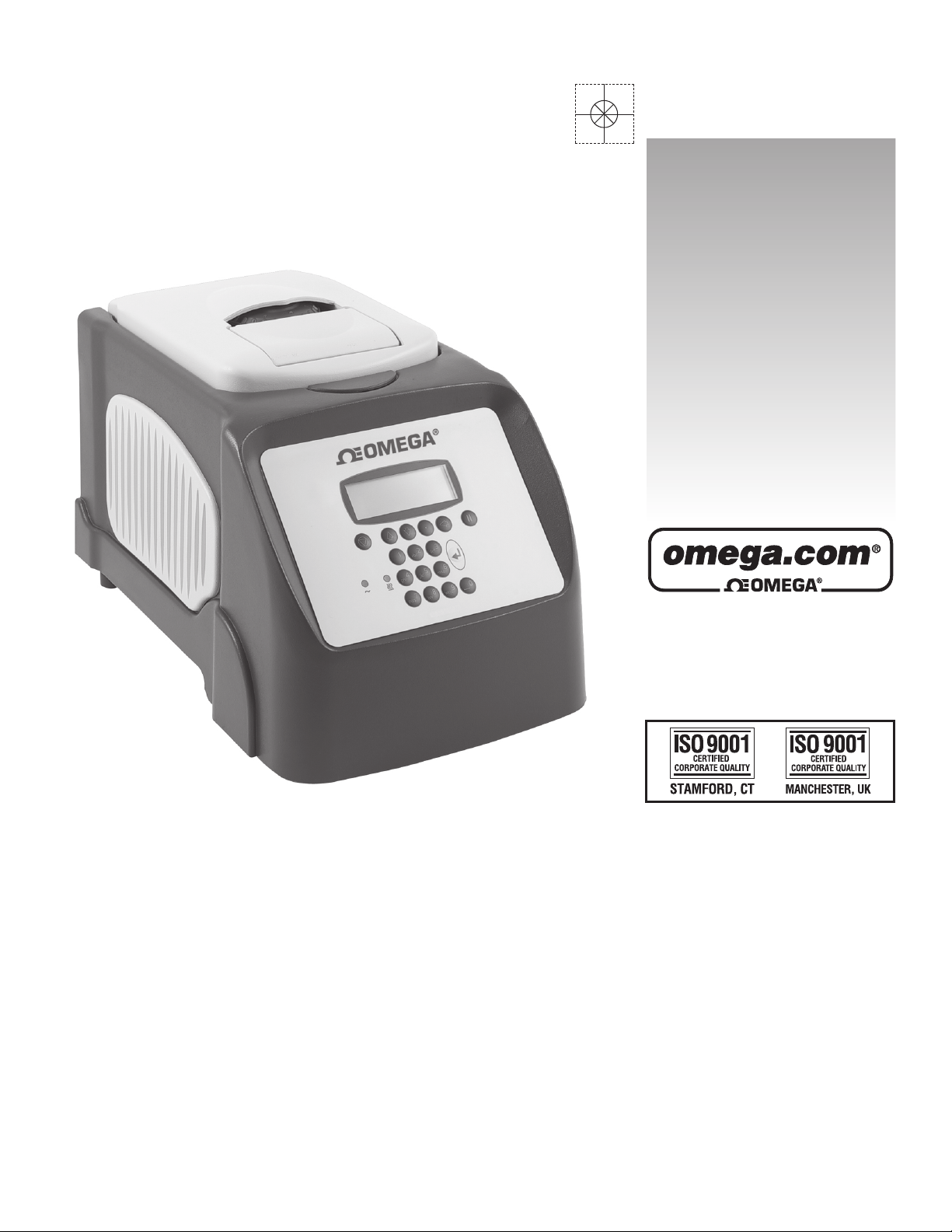
User’s Guide
Shop online at
omega.com
e-mail: [email protected]
For latest product manuals:
omegamanual.info
TCY 60 & TCY 90
Thermal Cyclers
Page 2

OMEGAnet®Online Service Internet e-mail
omega.com [email protected]
Servicing North America:
U.S.A.: Omega Engineering, Inc., One Omega Drive, P.O. Box 4047
ISO 9001 Certified Stamford, CT 06907-0047 USA
Canada: 976 Bergar
Laval (Quebec), Canada H7L 5A1
Toll-Free: 1-800-826-6342 TEL: (514) 856-6928
FAX: (514) 856-6886 e-mail: [email protected]
For immediate technical or application assistance:
U.S.A. and Canada: Sales Service: 1-800-826-6342/1-800-TC-OMEGA
Customer Service: 1-800-622-2378/1-800-622-BEST
Engineering Service: 1-800-872-9436/1-800-USA-WHEN
Mexico: En Español: 001 (203) 359-7803 FAX: (001) 203-359-7807
®
®
®
Servicing Europe:
Benelux: Managed by the United Kingdom Office
Czech Republic: Frystatska 184
733 01 Karviná, Czech Republic
Toll-Free: 0800-1-66342 TEL: +420-59-6311899
FAX: +420-59-6311114 e-mail: [email protected]
France: Managed by the United Kingdom Office
Toll-Free: 0800 466 342 TEL: +33 (0) 161 37 29 00
FAX: +33 (0) 130 57 54 27 e-mail: [email protected]
Germany/Austria: Daimlerstrasse 26
D-75392 Deckenpfronn, Germany
Toll-Free: 0 800 6397678 TEL: +49 (0) 7059 9398-0
FAX: +49 (0) 7056 9398-29 e-mail: [email protected]
United Kingdom: OMEGA Engineering Ltd.
ISO 9001 Certified One Omega Drive, River Bend Technology Centre, Northbank
Irlam, Manchester M44 5BD England
Toll-Free: 0800-488-488 TEL: +44 (0)161 777-6611
FAX: +44 (0)161 777-6622 e-mail: [email protected]
It is the policy of OMEGA Engineering, Inc. to comply with all worldwide safety and EMC/EMI
regulations that apply. OMEGA is constantly pursuing certification of its products to the European New
Appr
oach Directives. OMEGA will add the CE mark to every appropriate device upon certification.
The information contained in this document is believed to be correct, but OMEGA accepts no liability for any
errors it contains, and reserves the right to alter specifications without notice.
WARNING: These products are not designed for use in, and should not be used for, human applications.
Page 3

Contents
1. Introduction........................................ .... ........ .... .... .... ........ ... .... .... ........ .... .... .... ......4
2. Safety and installation........................................... .... .... .... ....... .... .... .... .... ........ .... ..5
3. Before switching on....................................................... .........................................7
4. TCY specification....................................................... .... ........ .... ... .... ........ .... .... .... ..8
5. User operation and consumables.........................................................................9
Heated lid ......................................................................................................................................... 9
Tubes or reaction vessels............................................................................................................... 10
0.5ml Tubes.................................................................................................................................... 10
Switching on................................................................................................................................... 10
6. Front panel controls.............................................................................................12
The LCD Display ............................................................................................................................ 12
Indicators........................................................................................................................................ 12
The keys......................................................................................................................................... 13
7. Programming the TCY..........................................................................................14
Programming Options..................................................................................................................... 15
Option 1: Creating programs using templates................................................................................. 15
Option 2: Creating a new program.................................................................................................. 19
Example programs ......................................................................................................................... 20
Programming.................................................................................................................................. 20
To program increment or decrement temperature or time. ............................................................. 24
To run a program............................................................................................................................ 27
8. Information ......................... .... .... ........ .... .... .... ........ .... .... ........ .... .... ... ........ .... .... ....29
9. Configuration ............................................................. .... .... ....... .... .... .... ........ .... ....30
10. Notes on transferring protocols from other thermal TCYs............................32
11. User maintenance............................................................................... ................33
Cleaning your TCY ......................................................................................................................... 33
Heater Block removal ..................................................................................................................... 33
12. Some frequently asked questions ....................................................................34
13. Additional information .......................................................................................35
Fault Finding................................................................................................................................... 35
Fuses ............................................................................................................................................. 35
The heated lid over-temperature cut-out.........................................................................................35
Insulation testing ............................................................................................................................ 35
Interchangeable blocks................................................................................................................... 35
3
Page 4

1. Introduction
The TCY provides the researcher with the means of accurately controlling the temperature profile
of samples. It has many applications, including DNA amplification
cycle samples between 4°C and 99°C.
The TCY is programmed by means of an integral keypad and LCD display. A program, which can
be recalled from memory, consists of:
a series of specified temperatures in °C
the times for which each specified temperature will be held (Hold Times)
the desired heating or cooling rates, in °C/sec, between each specified temperature
optional instructions as to whether the times and/or the temperatures are to increase or
decrease when a cycle is repeated.
The memory can store up to 37 programs.
Before using the TCY make sure you have read this manual carefully.
1
and sequencing. The TCY can
1
Aspects of the PCR process are claimed in USA Patent Nos. 4,683,195; 4,683,202, and 4,965,188. Use of the TCY in such
processes does not convey a licence to practice the processes themselves.
4
Page 5
2. Safety and installation
Operator Safety
Please read this manual carefully before using the TCY. If the equipment is not used in the manner
described in this manual the protection provided by the equipment might be impaired.
This instrument is designed to conform to international safety requirements and are fitted with an
over-temperature cut-out. If a safety problem should be encountered then switch off the unit at the
power socket and remove the plug from the electricity supply.
Warning
HIGH TEMPERATURES ARE DANGEROUS as they can cause serious burns to operators and
ignite combustible material. Users should be aware of the following potential hazards:
USE CARE AND WEAR PROTECTIVE GLOVES TO PROTECT HANDS
DO NOT use combustible substances near hot objects
DO NOT operate the instrument in the vicinity of inflammable liquids or gases
DO NOT place any liquid directly into the instrument, always use the appropriate
plastic consumables
After heating samples, remember that parts of the instrument, namely the lid and block and any
associated accessories may be very hot.
Unpacking
When unpacking please ensure that the following have been removed from the packaging:
OMEGA TCY
Power cable
Decontamination certificate
The user is advised to keep the original packaging in case the instrument ever needs to be returned
for service or repair. Omega Engineering accepts no responsibility for damage incurred unless the
unit is correctly packed and transported in its original packaging.
Please note that the screen of the thermal TCY is easily damaged by sharp objects such as pens,
pencils and fingernails. This type of damage will be considered as misuse and invalidate the
guarantee for this component.
Installation
The instrument should be carried using both hands. Never move or carry the instrument when in use
or connected to the power electricity supply.
1. The TCY includes a plug-in power cable.
2. Before connecting the instrument to the power supply, check the voltage against the rating
plate (located on the back of the unit). Ensure that the voltage selector switch (located
above the On/Off switch) is set to the appropriate voltage for the local supply. Please
note that the unit must be grounded to ensure proper electrical safety. Connect the power
cable to a suitable plug according to the table below.
Connection 220/240V, 50/60Hz Supply 110V/120V Supply, 50/60Hz
Live Brown Black
Neutral Blue White
Earth Green/yellow Green
5
Page 6

3. UK ONLY: The fused plug supplied with the power cable is fitted with a 10 Amp fuse to
protect the instrument and the user.
4. Units showing 230V, 50/60Hz on the rating plate also operate between 210 and 260V;
units with 120V, 50/60Hz also operate between 100 and 130V and units marked with
100V will operate between 90 and 110V. In all cases the heating rate will degrade by
approximately 8% at the extremes of the voltage range.
5. Plug the power cable into the socket on the back of the instrument.
6. Place the unit on a suitable flat bench or in a fume cupboard if required, ensuring that the
air inlet vents on the underside are free from obstruction. Position the instrument with a
minimum distance all round of 200mm from walls or other items and between each unit if
multiple units are being used to permit efficient air flow for each instrument.
7. Switch on the instrument:
I Power Switch On
O Power Switch Off
Replacement cable
Should the power lead need replacement, a cable of 1mm
2
of harmonized code H05VV-F
connected to an IEC320 plug should be used. IF IN DOUBT CONSULT A QUALIFIED
ELECTRICIAN.
The TCY is designed operate under the following conditions:
Indoor use
Ambient temperature range +5
o
C to +40oC
Altitude to 2000m
Relative humidity not exceeding 95%
Power supply fluctuations not exceeding 10%
Over voltage category II IEC 60364-4-443
Pollution degree 2
o
Note: The control specifications are quoted at an ambient temperature of 20
may deteriorate outside an ambient temperature of 10
o
C to 30oC.
C. The specification
The instrument has been tested for radio frequency interference and is certified under EN61326.
6
Page 7
3. Before switching on
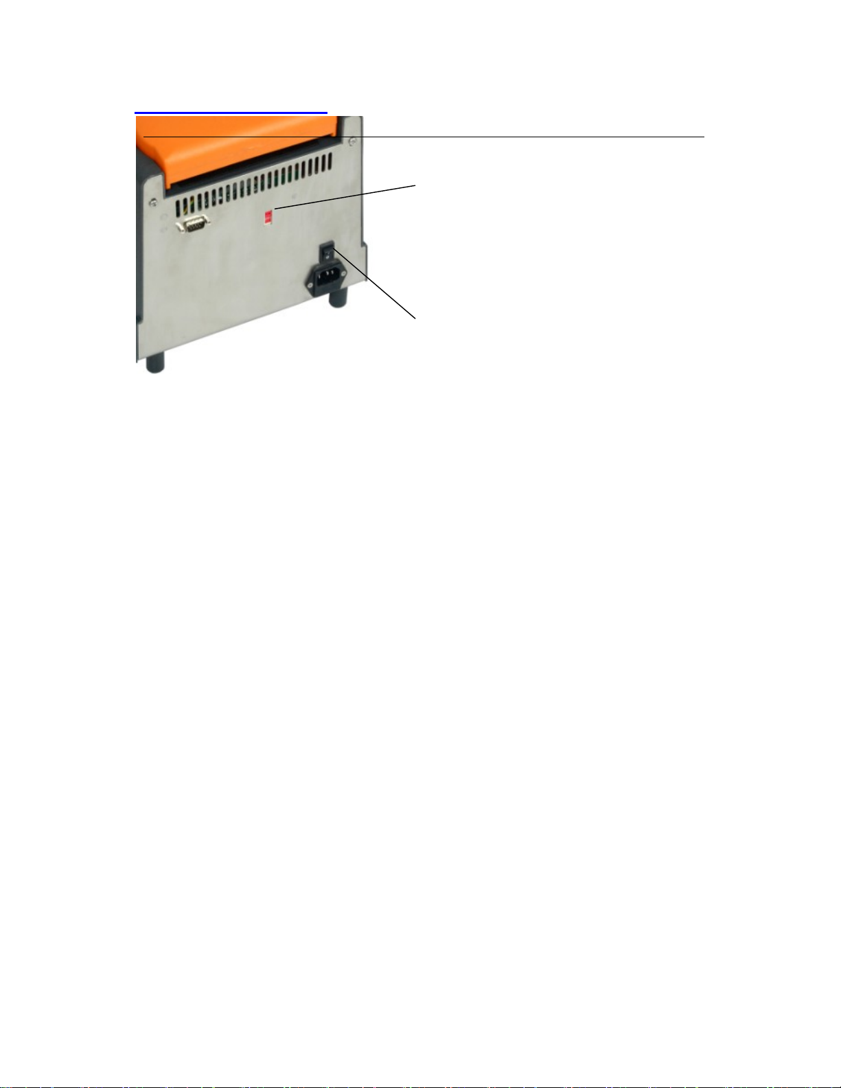
Ensure that the appropriate fuses are fitted
for your supply:
For 230V set the voltage selector switch
set to 230V and fit T6.3A fuses.
For 115V set th e switch to 115V and fit
T8A fuses.
For 110V the switch will be set to 115V
T8A fuses will be fitted.
On/Off switch
7
Page 8

4. TCY Specification
Temperature
Temperature range 4°C to 99°C
Temperature set point precision 0.1°C
Block uniformity (over full range) ± 0.5°C
Temperature accuracy ± 0.5°C
End of program cooling below ambient Yes
Heating/Cooling Rate
Heating rate, between 55°C and 90°C on a 50°C to 95°C step:
48 x 0.2 ml micro tubes 3.5°C/sec
30 x 0.5 ml micro tubes 3.5°C/sec
Cooling rate, between 90°C and 55°C on a 95°C to 50°C step:
48 x 0.2 ml micro tubes 2.5°C/sec
30 x 0.5 ml micro tubes 2.5°C/sec
Heated Lid
Heated lid enable/disable Yes
Selectable heated lid temperature 100°C to 115°C
Over-temperature cut-out Fixed at 145°C
Temperature sensor Thermistor
Heater type Etched foil
Heater power 132W
Warm up time 4 min approximately
(ambient to 105°C)
The heated lid will only come on if the set temperature is above 35°C
Programming
Program naming using alpha keys Yes
Program password protection Yes
Number of programs (3 step) 37
Maximum number of steps per stage 35
Maximum number of stages per program 25
Minimum hold time 1 sec
Maximum hold time 18 hrs
Incremental/decremental temperature Yes
Incremental/decremental step hold time Yes
Programmable ramp rate (heat or cool) Variable in 0.1°C/sec steps
Programmable ramp rate resolution 0.1°C
Running Programs
Pause button Yes
Stop button Yes
End of program alarm Yes
Auto restart on power fail Yes
Interconnectivity
Dimensions
Height 260mm
Width 220mm
Length 420mm
8
Page 9
Serial Port
Power
Power consumption 500W
The units are voltage selectable by a slide switch. When the unit is set to 115V it will
work at any voltage between 110V and 130V. When the unit is set to 230V it will
work at any voltage between 198V and 252V.
Units marked 100V will work at any voltage between 90 and 110V.
The performance will vary and will not necessarily meet the above typical
specification at the extremes of voltage.
5. User operation and consumables
Heated lid
To release the heated lid, lift the back of the handle as show and use it to lift the lid. To close the
lid, lower the lid onto the block containing the samples and press the handle down to shut.
close the lid without tubes being fitted in the block.
The heated lid has a rotating knob to adjust the lid pressure on the samples, allowing for a variety
of consumables to be used to adjust the pressure:
Place the samples in the block and place the lid in the
down position.
Adjust the orange rotating knob anticlockwise to give
the least pressure then close the lid fully.
Gently rotate the knob clockwise until you can feel
pressure beginning to be applied.
Rotate the knob a further quarter of a turn and this will
give the correct pressure.
1.
Do not
Do not over-tighten the knob as this will cause deformation of the silicone rubber membrane (where
use) and reduce the effectiveness of the lid. Once the pressure has been set it does not need to be
adjusted unless a different block or consumable is used.
9
Page 10

Tubes or reaction vessels
Omega Engineering does not recommend any specific tube or reaction vessel other than those
described in this manual. We recommend using reaction volumes between 20 and 200µl. The
tubes must withstand a pressure of 1 atmosphere at 100°C. Any vessel must be able to withstand
the temperatures you are using without any danger of them deforming to the point where they
fracture.
To test your tubes, put 25µl of water into each of 5 tubes and subject them to a typical thermal
cycling protocol. At the end of the program, measure the volume remaining using a micropipette. A
loss of more than 1 or 2µl indicates a vapour leak.
The amount of volume loss you observe and the change in reactant concentrations you can
tolerate determine the minimum volume that can be used. Typical volume losses of 1µl in 30
cycles allow the use of samples of 20µl or less.
During the final cool-down, a ring of condensation may form above the liquid level but below the
top of the sample block. This is normal and does not effect the reaction.
0.5ml Tubes
The heated lid mechanism of the TCY with the 0.5ml block is optimised for flat top tubes. In order
to fit the maximum number of tubes in the block, they need to be placed so that all the hinges are
in the same relative orientation. An example is illustrated below.
Place the tubes in the block in the same
orientation in order to achieve the
maximum capacity.
Always make sure the pressure on the
heated lid is balanced by spreading the
tubes across the block or inserting some
dummy tubes if necessary.
10
Page 11
Switching on
x
]
Omega
Version X.XX
Version X.XX
Block Type 96
Block 25x0.2ml
TC 3000
TCY
0.2ml
or 60x0.5ml
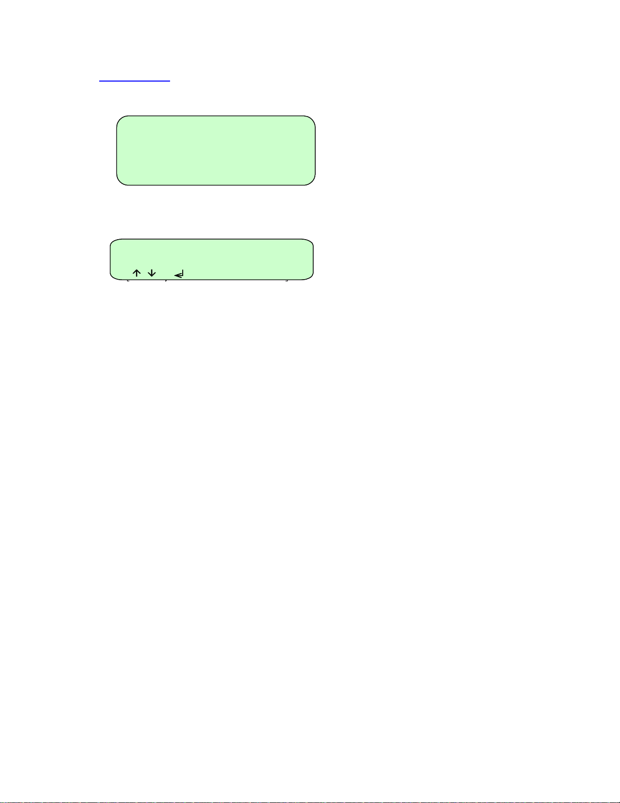
When you switch on the unit a screen
similar to the one shown here will appear
briefly. This indicates the software
version and block type installed in the
unit.
Programs [0]
Methods [0]
Information
Information
Configuration
Configuration
[ , to select
[ , to select ]
When the initial screen has disappeared
the screen shown here will automatically
appear. There are three options:
1. ‘Programs’ for creating and running
programs;
2. ‘Information’ for obtaining
information about the unit e.g. serial
number;
3. ‘Configuration’ for setting up
program defaults and settings.
Each of these is explained in detail in
section 6.
11
Page 12
6. Front panel controls
M
Operation or
Program lines
Prompt line
Down
Up Decimal Point
& Insert
End Delete
Alpha/Numeric
keys
Status Pause
Power Enter
The LCD Display
Programs [0]
ethods [0]
Information
Information
Configuration
Configuration
[ , to select ]
[ , to select ]
-- Stage 1 ----------
-- Stage 1 ----------
-- Stage 1 ---------Number cycles 10
Number cycles 10
Number cycles 10
Step 94.0ºC 00m30 max
Step 94.0ºC 00m30 max
Step 94.0ºC 00m30 max
[‘.’ to insert step ]
[‘.’ to insert step ]
[‘.’ to insert step ]
[ , to edit ]
[ , to edit ]
[ , to edit ]
[ to delete step ]
[ to delete step ]
[ to delete step ]
Indicators
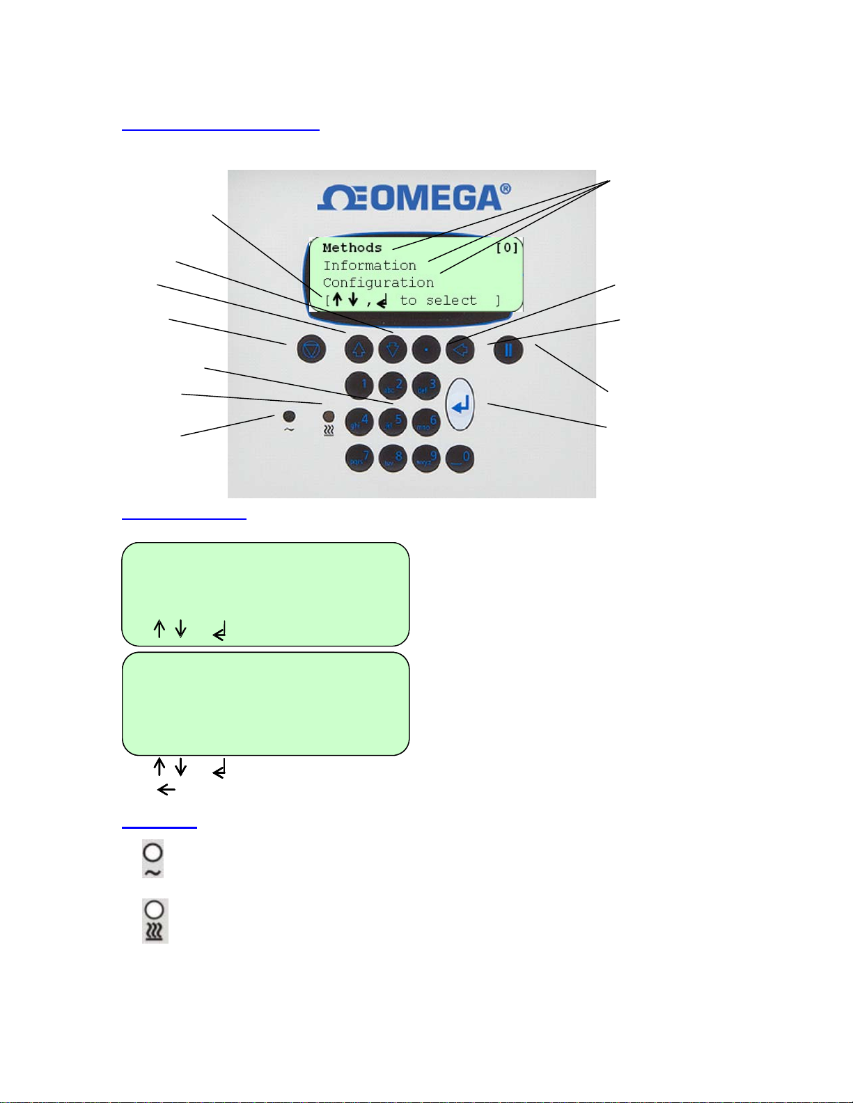
Power: This indicator is lit when there is power to the TCY.
Status: This indicator is lit when the TCY is running a program. It is off when
the unit is stopped. It will flash and beep slowly when the unit is paused. It will
flash after a five second quick sequence of beeps when the unit reaches its
final hold temperature.
The TCY has a four line LCD display. The
top three lines are information or program
lines, while the bottom line is a prompt
line. The active line flashe s on screen and
is shown in bold in this manual.
The bottom line may change or flash
between two or three different prompts
depending upon which program line is
active. An example of a prompt line which
flashes between three different prompts is
shown here.
12
Page 13
The keys
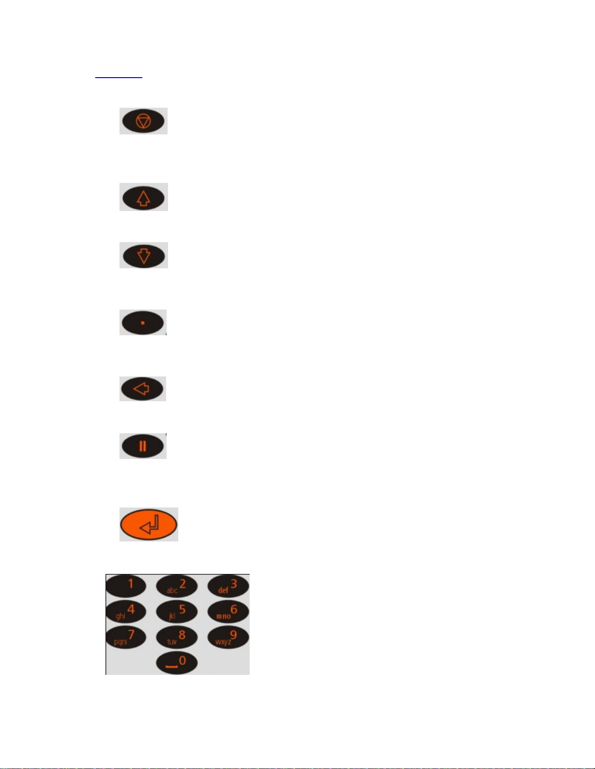
The End, Finish or Exit key
The Up arrow key
The Down arrow key
The Decimal Point and Insert key
The Delete key
The Pause key
The Enter or Accept key
The Alpha/Numeric keys
The “End” or “Finish” key is used to finish
editing programs or to exit a program. It is
also used to exit a sequence of key
operations.
The “Up arrow” key is used for scrolling up
through the lines on the screen. It is also
used to increase certain fields when editing.
The “Down arrow” key is used for scrolling
down through the lines on the screen. It is
also used to decrease certain fields when
editing.
The “Decimal Point” key is used when
editing numeric fields. It is also used as an
Insert key during program editing to insert
additional steps and other field sets.
The “Delete” key is used during program
editing to delete steps and stages.
The “Pause” key is used during program
editing to insert a pause after a stage or to
insert increment and decrement times and
temperatures. It is also used to pause a
program when it is running.
The “Enter” key is used to enter an
operation or the edit mode. It is also used to
‘Accept’ a field or program change.
The “Alpha/N umeric” keys are used to enter
numbers and letters during programming. If
it is a numeric field then numbers will be
inserted; if it is an alpha field then letters
will be inserted. Each key will cycle through
the letters shown on the key (0 will insert a
space). To insert a number, press and hold
the appropriate key.
13
Page 14
7. Programming the TCY
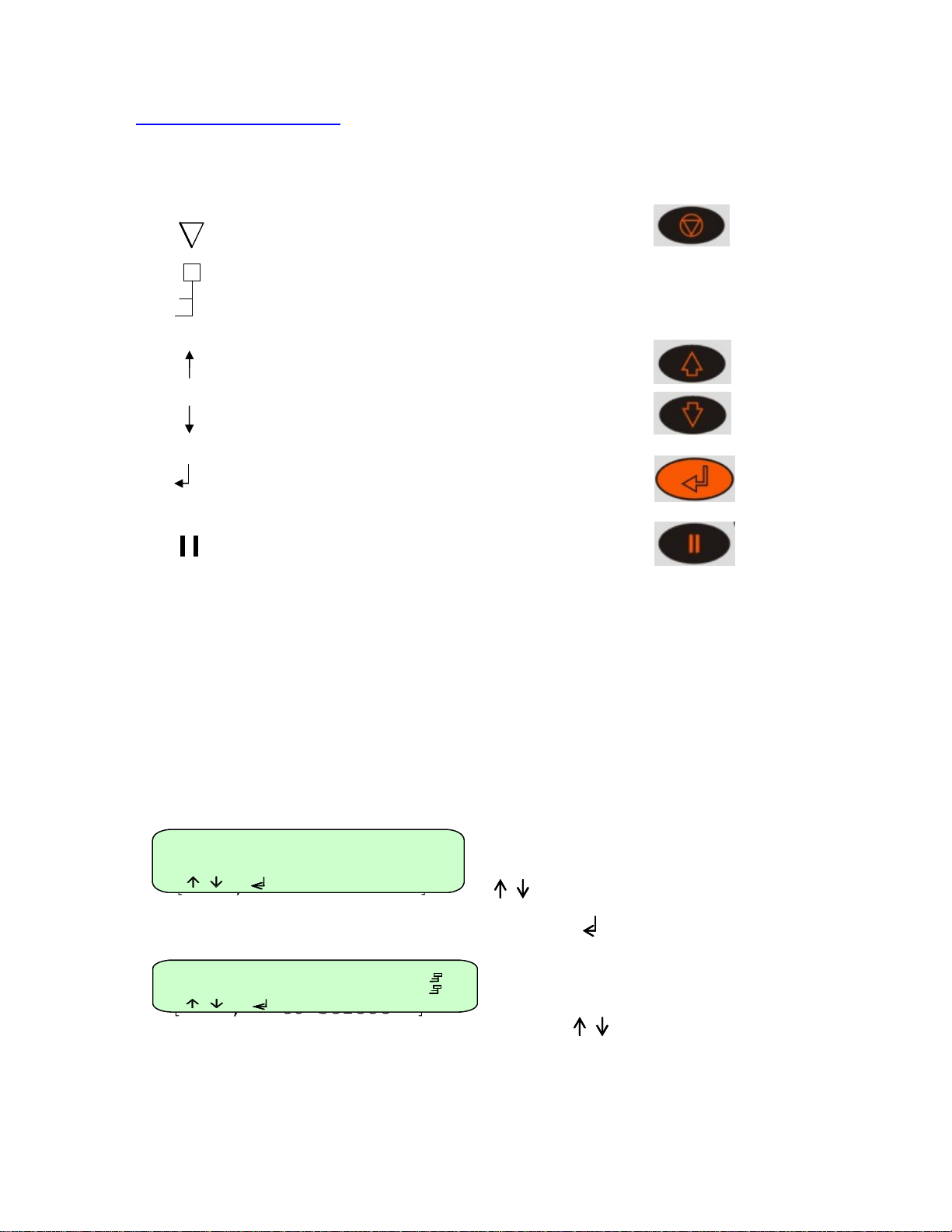
The table below illustrates the symbols which appear on the LCD display and the relevant keypad
button to which they refer.
The following terms are used when programming the TCY:
Stage
Cycle
Step
Programs [0]
Methods [0]
Information
Information
Configuration
Configuration
[ , to select ]
[ , to select ]
* * New Methods ** []
* * New program ** []
2 STEP TEMPLATE 501
2 STEP
3 STEP TEMPLATE 502
3 STEP
[ , to select ]
[ , to select ]
In the prompt line is equivalent to the “End” key.
On a program line means the program is locked; it
can be copied and then edited but not edited
directly.
Up arrow
Down arrow
Enter
Pause
A ‘Stage’ is the name given to the main repeated part of a program
containing the ‘Steps’ to be repeated. A program can contain a maximum
of 25 stages although typically only one or two are used.
A ‘Cycle’ is the number of repetitions of a ‘Stage’
A ‘Step’ is a user defined program line containing a temperature, a hold
time and ramp rate. Typically three steps are created within one ‘Stage’.
To enter the programming section of the TCY
Ⅴ software, highlight ‘methods’ using the
“Up Arrow” or “Down Arrow”
keys
Press “Enter”
This screen lists all the pr ograms saved on
the unit. Use the “Up Arrow” and “Down
Arrow” keys to scroll through the list.
The number next to the program name is the
unique “Speed dial” number allocated to the
program for rapid retrieval (see below).
14
Page 15
Programming Options
[2]
C
9
C
C
7
C
9
C
C
7
3
H
P
P
-------
-
In d
9
H
S
N
S
º
C 0
S
C 0
S
º
C 0
-------
-
F
F
3
H
P
P
-------
-
In d
9
H
S
N
S
º
C 0
S
C 0
S
º
C 0
-------
-
Post
run7
P
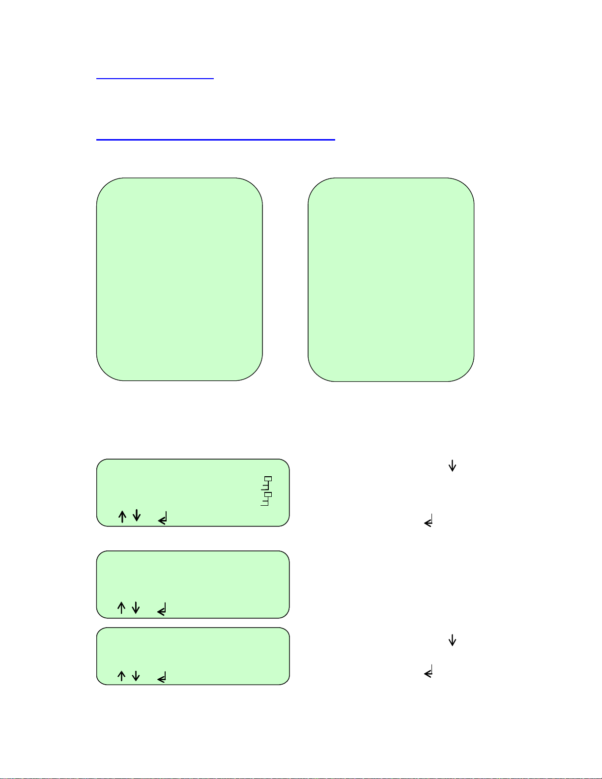
There are two options available for creating programs on the TCY :
1. Copy and edit one of the pre-written templates.
2. Create a new program from the defaults.
Option 1: Creating programs using templates
There are two pre-written basic PCR templates: a two-step and a three-step template. These can
be copied and modified as required. "In denat" stands for Initial Denaturing.
2 STEP TEMPLATE
Heated Lid 105 º
Heated Lid 105 º
Preheat Lid on
Preheat Lid on
Pause off
Pause off
- - - - - - - - - - -
- - - - - - - - - - In denat
In denat
Hot Start off
Hot Start off
- - - Stage 1 - - - -
- - - Stage 1 - - - Number cycles 30
Number cycles 30
Step 94.0 º
Step 94.0 º
Step 68.0 º
Step 68.0 º
- - - - - - - - - - -
- - - - - - - - - - Fina Extn
Post run
Final hold 10.0
Post hold 10.0
Other templates available include Ice bucket (incubation at 4ºC), Ligation (incubation at 15ºC) and
an RT-PCR template.
* * New progr a
-*New*-
2 STEP [2]
2 STEP TEMPLATE 501
2 STEP
3 STEP
3 STE
3 STEP 3
[ , to select ]
[ , to select ]
[ , to select ]
[ , to select ]
2 STEP TEMPLATE [501]
Run Program
Run Method
View Program
View Method
[ , to select ]
[ , to select ]
[ , to select ]
Run program
Run Method
View program
View Method
Copy program
Copy Method
[ , to select ]
[ , to select ][ , to select ]
2 STEP
4.0 º C 5m00
4.0 º C 5m00
0m30 max
0m30 max
1m00 max
1m00 max
2.0 º C 5m00
2.0 º C 5m00
2 STEP
ºC
ºC
- - -
- - -
STEP TEMPLATE
STEP
eated Lid 105 º C
eated Lid 105 º C
reheat Lid on
reheat Lid on
ause off
ause off
- - -
- - -
enat
enat
ot Start off
ot Start off
tage 1
tage 1
umber cycles 30
umber cycles 30
tep 94.0
tep 94.0
tep 55.0
tep 55.0
tep 72.0
tep 72.0
inal Extn72.0º C 5m00
inal hold 10.0 º C
ost hold 10.0 º C
Use the “Down Arrow” key to select an
existing ‘Template’ program from the
menu, e.g. ‘2 Step Template’ or ‘3 Step
Template’.
Press the “Enter” key to accept it.
The Template is already defined and can
be run as it is or easily copied, modified
and saved under a new name.
Use the “Dow n Arrow” key to select
‘Copy Program’
Press the “Enter” key to accept it.
4.0º C 5m00
4.0º C 5m00
- - - -
- - - -
m30 max
m30 max
m30 max
º
º
m30 max
m30 max
m30 max
- - -
- - -
2.0º C 5m00
15
Page 16
Heated Lid 105ºC
Heated Lid 105ºC
Heated Lid 105ºC
Preheat Lid on
Preheat Lid on
Preheat Lid on
[ , to edit ]
[ , to edit ]
[ , to edit ]
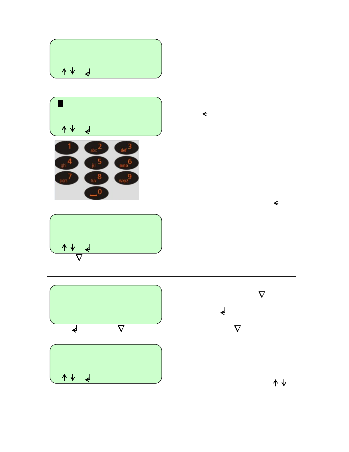
To give a program a name
Heated Lid 105ºC
Heated Lid 105ºC
Heated Lid 105ºC
Heated Lid 105ºC
Preheat Lid on
Preheat Lid on
Preheat Lid on
Preheat Lid on
[ , to edit ]
[ , to edit ]
[ , to edit ]
[ , to edit ]
Heated Lid 105ºC
Heated Lid 105ºC
Heated Lid 105ºC
Heated Lid 105ºC
Preheat Lid on
Preheat Lid on
Preheat Lid on
Preheat Lid on
[ , to edit ]
[ , to edit ]
[ , to edit ]
[ , to edit ]
[ to save ]
[ to save ]
[ to save ]
[ to save ]
To save the program
Heated Lid 105ºC
Heated Lid 105ºC
Preheat Lid on
Preheat Lid on
[ SAVE ? ]
[ SAVE ? ]
[ YES or No ]
[ YES or No ]
Run Program
Run Program
Run Program
View Program
View Program
View Program
[ , to select ]
[ , to select ]
[ , to select ]
UNNAMED #
UNNAMED #
UNNAMED #
UNNAMED #
UNNAMED #
UNNAMED #
UNNAMED #
DONNA
DONNA
DONNA
DONNA
DONNA
DONNA
DONNA [7]
DONNA [7]
DONNA [7]
A new name can now be given to the
copied program (see below).
To type in a name for the program, press
"Enter" and a cursor will appear in the
position shown.
Using the keypad, type in the name you
wish to give the program.
The letters will scroll round with
successive presses; for example the “2”
key will give ‘A’ with one press; ‘B’ with
two presses; ‘C’ with three presses and
‘2’ with fou r presses. Five presses will
again give ‘A’.
When the name is complete, press
"Enter"
There are now two options:
1. Save the program and run it as it
is or
2. Edit the program then save and
run it.
A program can only be run once it has
been saved. Press the “End” key.
The prompt line will flash between
'SAVE?' and 'YES or NO'.
Press “Enter” for ‘Yes’ to save the
changes you have made.
If you press “End” for ‘No’ then all
the changes you have made will be lost.
The program is now ready to run and will
be allocated with a unique ‘Speed dial’
number which can be used to rapidly
locate the program from the main startup screen.
“Up Arrow” or “Down Arrow” keys
to scroll through the remaining list of
options.
16
Page 17
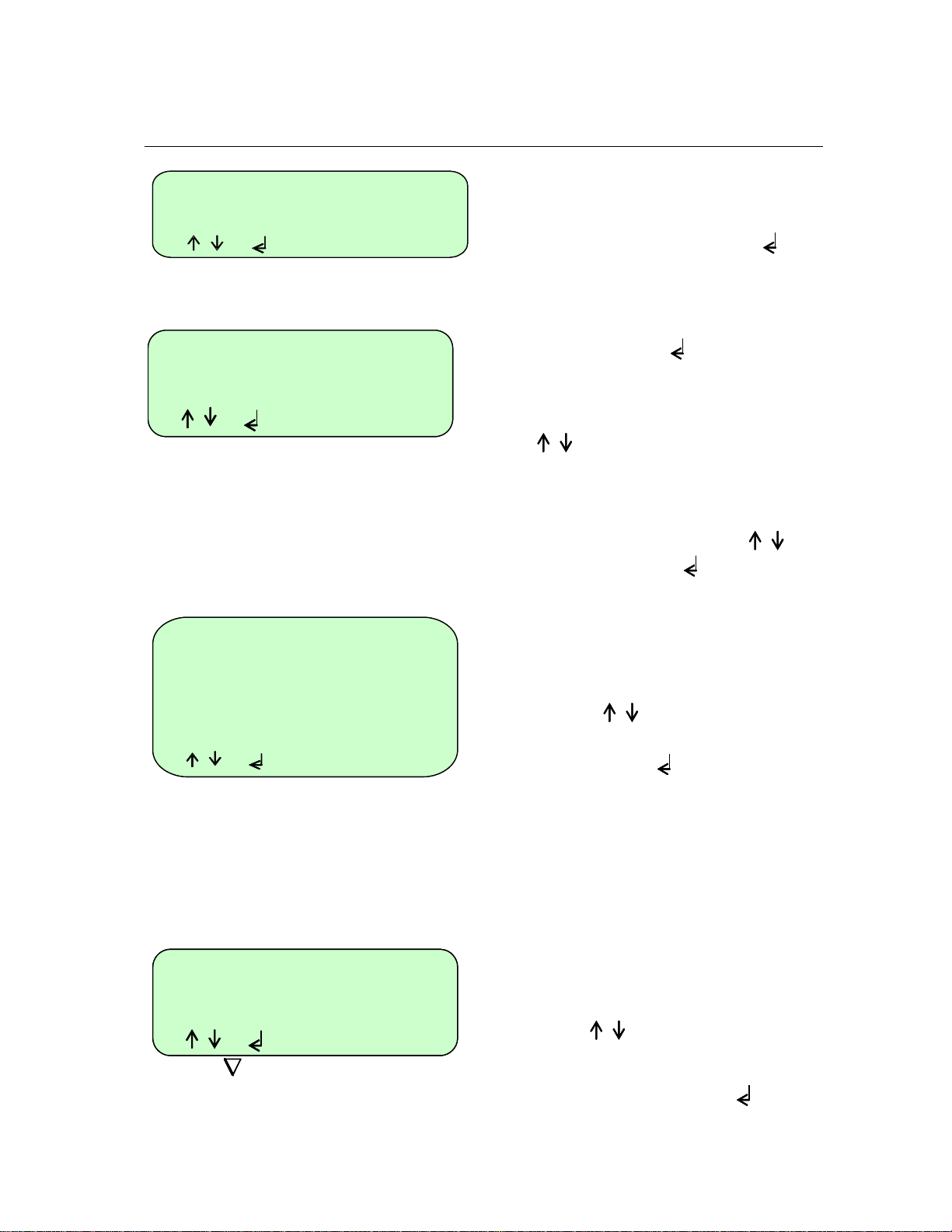
To edit a field or step in an existing
program
Programs [0]
Methods [0]
Information
Information
Configuration
Configuration
[ , to select ]
[ , to select ]
DAVID 8 [D]
DAVID 8 [D]
DAVID 8 [D]
DONNA 7
DONNA 7
DONNA 7
[ , to select ]
[ , to select ]
[ , to select ]
Run program
Run method
View program
View method
Edit program
Edit method
Copy method
Copy program
Delete program
Delete method
Set password
Set password
Set password
[ , to select ]
[ , to select ]
[ , to select ]
Edit a selected field or step
Heated Lid 105ºC
Heated Lid 105ºC
Heated Lid 105ºC
Heated Lid 105ºC
Preheat Lid on
Preheat Lid on
Preheat Lid on
Preheat Lid on
[ , to edit ]
[ , to edit ]
[ , to edit ]
[ , to edit ]
[ to save ]
[ to save ]
[ to save ]
[ to save ]
DONNA [7]
DONNA [7]
DONNA [7]
DONNA
DONNA
DONNA
DONNA
When the unit is switched on the display
will show this screen.
If known, type in the ‘Speed dial’ number
for the required program and press
“Enter” This will take you directly to
the required program.
If you do not know the ‘Speed dial’
number, press “Enter” to access the
list of stored programs.
Either:
1. Scroll to the required program using
the “Up Arrow” or “Down Arrow” keys
or
2. Type the first letter of the program
name in the ‘New program’ field; this
will then list all the program n ames
beginning with that letter. Use the “Up
Arrow” or “Down Arrow” keys to
select the required program.
Press “Enter” to accept
The full set of options for a program is
shown here; these are shown on the LCD
screen three lines at a time.
Use the “Down Arrow” and/or the “Up
Arrow” keys to select the option
you require.
Press the “Enter” key to select the
option.
Select ‘Edit program’ and a screen similar
to this will appear.
Use the “Down arrow” and/or the “Up
arrow” keys to select the field or
step you want to edit.
You can now edit the active field or step
by first pressing the “Enter ” key
17
Page 18
º
C
º
C
º
C
º
C
Heated Lid 105ºC
Heated Lid 105ºC
Preheat Lid on
Preheat Lid on
[ edit temperature ]
[ edit temperature ]
[ to disable ]
[ to disable ]
Heated Lid 105ºC
Heated Lid 105ºC
Preheat Lid on
Preheat Lid on
[ to change ]
[ to change ]
[ turn on/off ]
[ turn on/off ]
Pause off
Pause off
Pause off
---------------------
---------------------
---------------------
In denat 94.0ºC 00m30
In denat 94.0ºC 00m30
In denat 94.0ºC 00m30
[ edit temperature ]
[ edit temperature ]
[ edit temperature ]
[ to disable ]
[ to disable ]
[ to disable ]
Pause off
Pause off
---------------------
---------------------
In denat 94.0ºC 00m30
In denat 94.0ºC 00m30
[ edit time ]
[ edit time ]
[ . for hrs/mins ]
[ . for hrs/mins ]
---------------------
---------------------
---------------------
Post run
Fin extn
Fin extn
Fin hold 10.0
Fin hold 10.0
Post hold 10.0
[ , to edit ]
[ , to edit ]
[ , to edit ]
[ , to edit ]
[ to save ]
[ to save ]
[ to save ]
[ to save ]
DONNA
DONNA
DONNA
DONNA
72.0 º C 5m00
72.0 º C 5m00
72.0 º C 5m00
72.0 º C 5m00
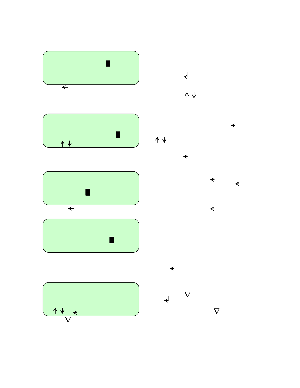
To edit a temperature, type in the required
temperature. In the example here, the
heated lid temperature is being edited.
Press “Enter” to accept.
Use the “Down Arrow” and/or the “Up
Arrow” keys to select the next field
or step you wish to edit.
To edit a field with on/off settings, first
select the field and press “Enter”
Use the “Up Arrow” and “Down Arrow”
keys to toggle between the
settings.
Press “Enter” to accept.
To edit a step with both a temperature and
a time, first press “Enter” and type in
the new temperature. Press “Enter”
again. Now type in the new time. The
default is minutes.
1. For whole minutes, type the number
required then “Enter”
2. To toggle between minutes and hours,
use the “Decimal Point” key.
3. For values less than 1 minute, first
press the “Decimal Point” key followed
by the number of seconds required.
4. For minutes and seconds, type the
number of minutes followed by the
“Decimal Po int” key then the number
of seconds.
Once the values have been added, press
“Enter” to accept.
Once you have finished editing and you
are happy with the changes, press the
“End” key followed by the “Enter”
key to save.
If you press the “End” key a second
time for ‘No’ then all the changes you have
made will be lost.
18
Page 19
To copy a selected program
UNNAMED #
UNNAMED #
UNNAMED #
UNNAMED #
Heated lid 105ºC
Heated lid 105ºC
Heated lid 105ºC
Heated lid 105ºC
Preheat lid on
Preheat lid on
Preheat lid on
Preheat lid on
[ , to edit ]
[ , to edit ]
[ , to edit ]
[ , to edit ]
[ to save ]
[ to save ]
[ to save ]
[ to save ]
To delete a selected program
delete program
delete program
[ SURE ? ]
[ SURE ? ]
[ Yes or No ]
[ Yes or No ]
To set a password for a selected
program
New passwd
New passwd
[ to accept ]
[ to accept ]
[ to exit ]
[ to exit ]
DONNA
DONNA
DONNA
DONNA
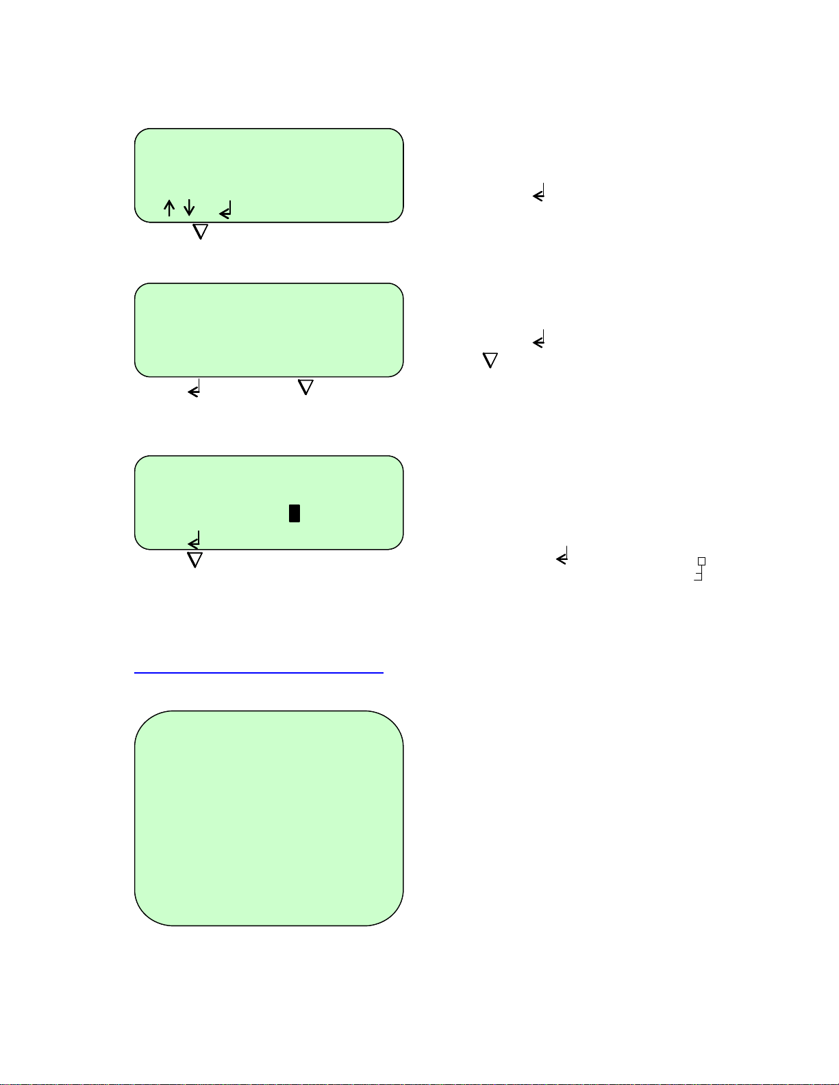
If you select ‘Copy program’ a screen
similar to this will appear and the software
will automatically give the program the
next number until it is named.
Press “Enter” and type in a new name.
You will then be able to edit the program
as previously described.
If you select ‘Delete program’ a screen
similar to this will appear.
Press “Enter” to delete the program or
“End” to return to the program screen.
If you want to password protect the
program so that other users cannot edit it,
select ‘Set password’. A screen similar to
this will appear.
Type in the password you wish to give it
and press “Enter” . The program list
will then display the key symbol next to
the name to show that it is locked.
Other users will still be able to copy/view
your program but not edit it.
Option 2: Creating a new program
A second option is to create a completely new program without using templates.
Heated lid 105
Heated lid 105
Preheat lid off
Preheat lid off
Pause off
Pause off
-
-
- - - - - - - - - -
- - - - - - - - - -
In denat
In denat
Hot Start off
Hot Start off
-
- - - - - - - - - -
-
- - - - - - - - - -
Fin extn
Post run
Fin hold 10.0
Post hold 10.0
UNNAMED #
UNNAMED #
94.0
94.0
72.0 º C 5m00
72.0 º C 5m00
C 5m00
C 5m00
º
º
ºC
ºC
ºC
ºC
A number of typic al values are pre-ente r ed
including:
Heated lid temperature
Preheat lid
Initial denaturation
Hot start
Final extension
Final hold
These values can be edited and the
additional stages and steps required for
cycling can be added by following the
instructions detailed on the following
pages.
19
Page 20
Example programs
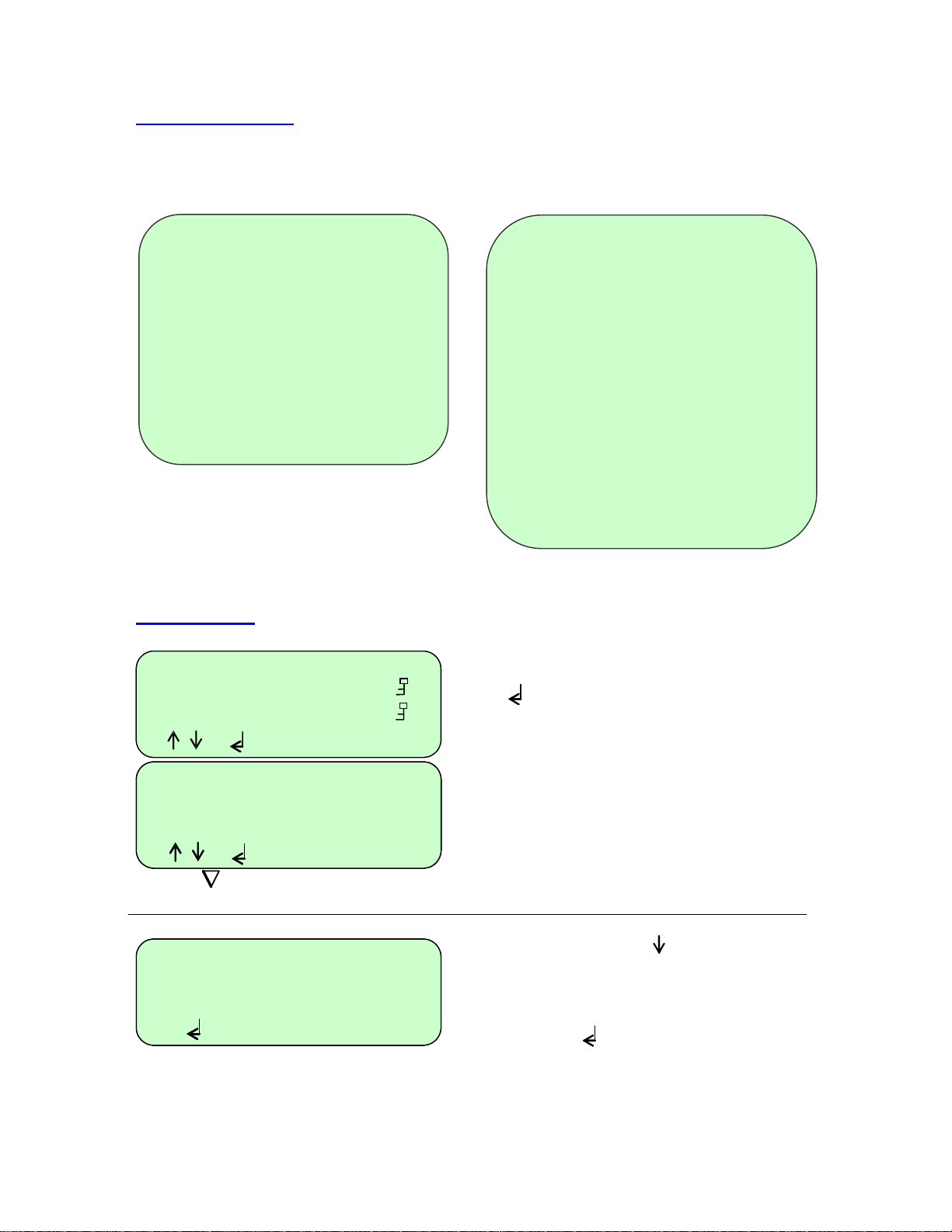
A couple of example thermal cycling programs are shown below.
Typical 3-Step PCR
Heated Lid 105
Preheat Lid on
Pause off
- - - - - - - - - - - - - - - -
In denat 94°c 5min
Hot Start off
- - - - - - Stage 1 - - - - - -
Number Cycles 30
Step 94°c 0m30 max
Step 55°c 0m30 max
step 72°c 0m30 max
- - - - - - - - - - - - - - - -
Post run 72°c 5m
Post hold 4ºC 10m
3-Step PCR with multiple ‘Stages’
Heated Lid 105
Preheat Lid on
Pause off
- - - - - - - - - - - - - - - -
In denat 94
Hot Start off
- - - - - - Stage 1 - - - - - -
Number Cycles 10
step 94
step 60
step 72
- - - - - - Stage 2 - - - - - -
Number Cycles 20
step 94
step 55
step 72
- - - - - - - - - - - - - - - -
Post run 72
Post hold 4ºC 10m
°c 5min
°c 0m30 max
°c 0m30 max
°c 0m30 max
°c 0m30 max
°c 0m30 max
°c 0m30 max
°c 5m
Programming
* * New program ** []
-*New*- []
2 STEP TEMPLATE 501
2 STEP 2
3 STEP TEMPLATE 502
3 STEP 3
[ , to select ]
[ , to select ]
Heated lid 105ºC
Heated lid 105ºC
Heated lid 105ºC
Heated lid 105ºC
Preheat lid on
Preheat lid on
Preheat lid on
Preheat lid on
[ , to edit ]
[ , to edit ]
[ , to edit ]
[ , to edit ]
[ to save ]
[ to save ]
[ to save ]
[ to save ]
To add a stage and then edit it
In denat 94.0ºC 5m00
In denat 94.0ºC 5m00
In denat 94.0ºC 5m00
Hot Start off
Hot Start off
Hot Start off
-----------
-----------
-----------
[ to insert stage ]
[ to insert stage ]
[ to insert stage ]
UNNAMED #
UNNAMED #
UNNAMED #
UNNAMED #
Create a new program by selecting
-* New *- from the menu and press “Enter”
Give the program a name and edit any of
the default fields as described above.
Use the “Down Arrow” key to scroll to
the dotted line below ‘Hot Start’; it will
start to flash.
Press "Enter" to insert a stage
A new stage will be in se rt ed w h i ch
consists of a ‘Number cycles’ field and
one step.
20
Page 21
-- Stage 1 ----------
-- Stage 1 ---------Number cycles
Number cycles
Step 94.0ºC 00m30 max
Step 94.0ºC 00m30 max
[ edit no. cycles ]
[ edit no. cycles ]
-- Stage 1 ----------
-- Stage 1 ----------
-- Stage 1 ---------Number cycles 10
Number cycles 10
Number cycles 10
Step 94.0ºC 00m30 max
Step 94.0ºC 00m30 max
Step 94.0ºC 00m30 max
[‘.’ to insert step ]
[‘.’ to insert step ]
[‘.’ to insert step ]
[ , to edit ]
[ , to edit ]
[ , to edit ]
[ to delete step ]
[ to delete step ]
[ to delete step ]
To insert additional steps
-- Stage 1 ----------
-- Stage 1 ----------
-- Stage 1 ----------
Number cycles 10
Number cycles 10
Number cycles 10
Step 94.0ºC 00m30 max
Step 94.0ºC 00m30 max
Step 94.0ºC 00m30 max
[‘.’ to insert step ]
[‘.’ to insert step ]
[‘.’ to insert step ]
[ , to edit ]
[ , to edit ]
[ , to edit ]
To delete a step
-- Stage 1 ----------
-- Stage 1 ----------
-- Stage 1 ---------Number cycles 10
Number cycles 10
Number cycles 10
Step 94.0ºC 00m30 max
Step 94.0ºC 00m30 max
Step 94.0ºC 00m30 max
[‘.’ to insert step ]
[‘.’ to insert step ]
[‘.’ to insert step ]
[ , to edit ]
[ , to edit ]
[ , to edit ]
[ to delete step ]
[ to delete step ]
[ to delete step ]
-- Stage 1 ----------
-- Stage 1 ---------Number cycles 10
Number cycles 10
Step 94.0ºC 00m30 max
Step 94.0ºC 00m30 max
[ DEL STEP ? ]
[ DEL STEP ? ]
[ Yes or No ]
[ Yes or No ]
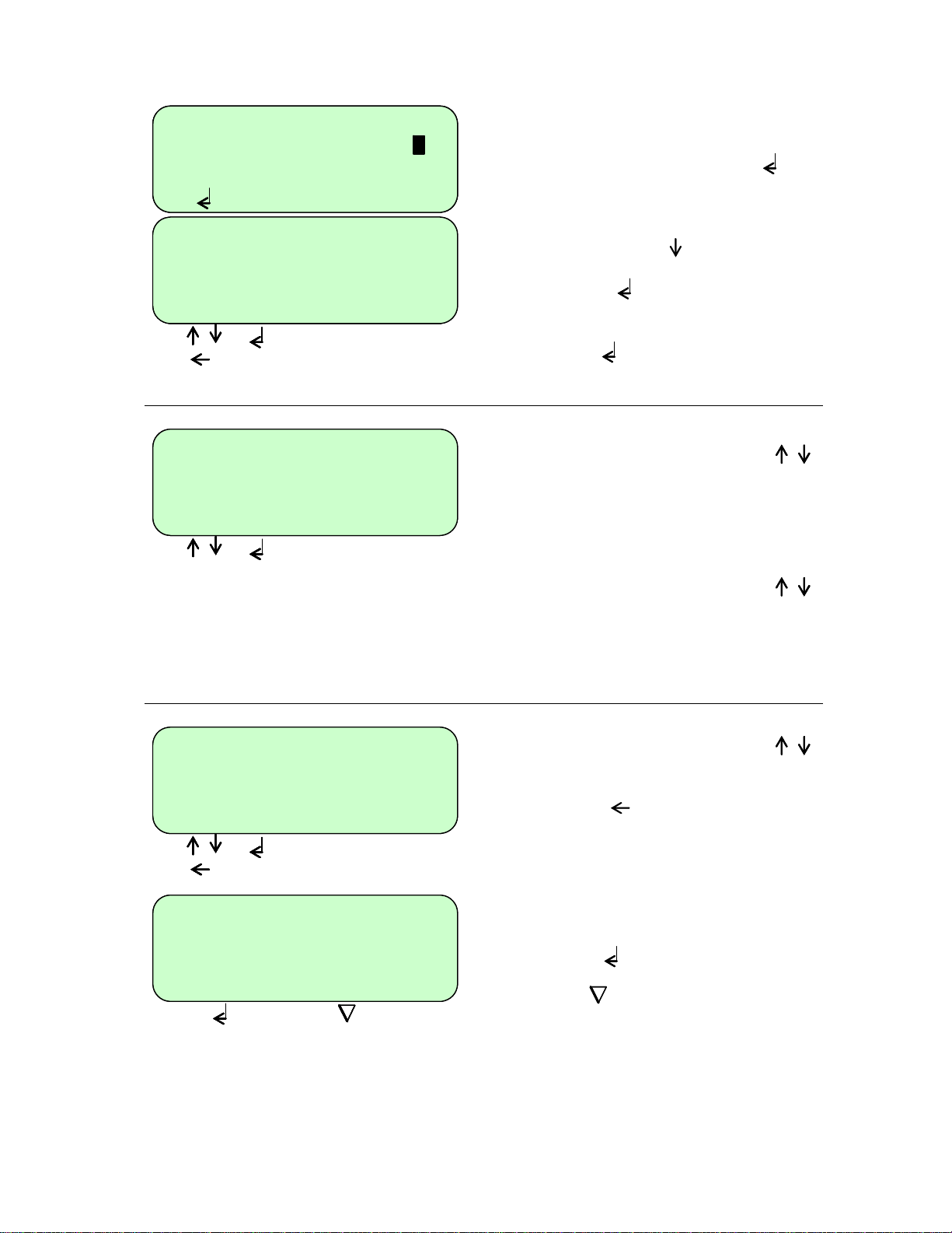
Edit the number of cycles by typing the
number required then press "Enter"
Use the “Down Arrow” key to move to
the step.
Press “Enter” to edit the step as
described above.
Press “Enter” again to accept.
To insert a new step before the first step,
use the “Up Arrow” or “Down Arrow”
keys to select ‘Number cycles’.
Press the “Decimal Point” key to insert a
new step.
To insert a new step after an existing step,
use the “Up Arrow” or “Down Arrow”
keys to select the step.
Press the “Decimal Point” key to insert a
new step.
Use the “Up Arrow” or “Down Arrow”
keys to select the step you wish to delete.
Press "Delete" to delete the step.
The prompt line will flash between 'DEL
STEP?' and 'YES or NO'.
Press “Enter” to delete the step.
or
Press “End” to return to editing the
step.
21
Page 22
To add a new stage before an existing
-
º
C
-
º
C
-
º
C
one
-- Stage 1 ----------
-- Stage 1 ----------
Number cycles 10
Number cycles 10
Step 94.0ºC 00m30 max
Step 94.0ºC 00m30 max
[ to insert stage ]
[ to insert stage ]
[ to delete stage ]
[ to delete stage ]
To add a new stage at the end
- - - - - - - - - -
- - - - - - - - - -
- - - - - - - - - -
Post run 72.0 º C 5m00
Fin extn 72.0 º C 5m00
Post hold 10.0
Fin hold 10.0
[ to insert stage ]
[ to insert stage ]
[ to insert stage ]
To delete a stage
-- Stage 1 ----------
-- Stage 1 ----------
Number cycles 10
Number cycles 10
Step 94.0ºC 00m30 max
Step 94.0ºC 00m30 max
[ to insert stage ]
[ to insert stage ]
[ to delete stage ]
[ to delete stage ]
-- Stage 1 ----------
-- Stage 1 ----------
Number cycles 10
Number cycles 10
Step 94.0ºC 00m30 max
Step 94.0ºC 00m30 max
[ DEL STAGE ? ]
[ DEL STAGE ? ]
[ YES or No ]
[ YES or No ]
72.0 º C 5m00
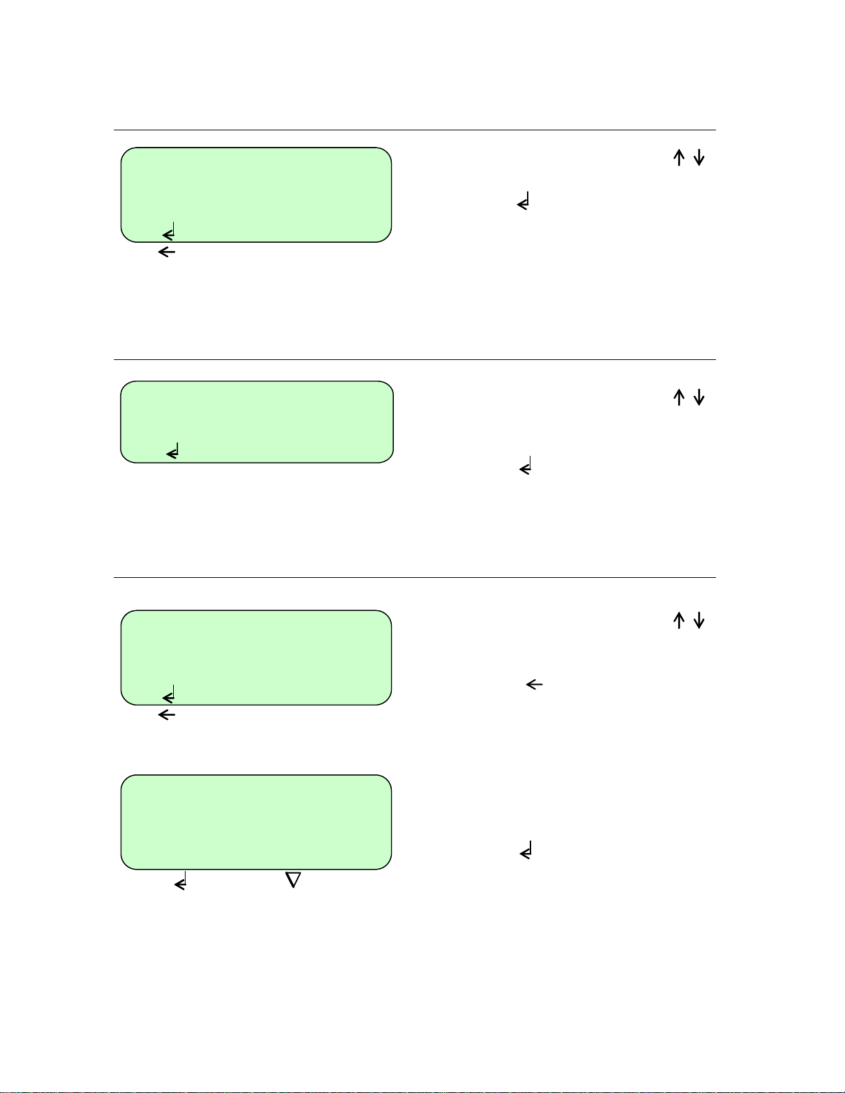
Use the “Up Arrow” or “Down Arrow”
keys to highlight the stage number.
Press "Enter"
A new stage will be added before the
existing stage. The other stage numbers
will be adjusted as appropriate. The new
stage can now be edited as described
above.
Use the “Up Arrow” or “Down Arrow”
keys to highlight the dotted line below the
last stage.
Press "Enter"
A new stage will be added with the next
consecutive number. The new stage can
now be edited as described above.
Use the “Up Arrow” or “Down Arrow”
keys to highli ght the stage you wish to
delete.
Press "Delete"
The prompt line will flash between 'DEL
STAGE?' and 'YES’ or ‘NO'.
Press “Enter” to delete the stage.
22
Page 23
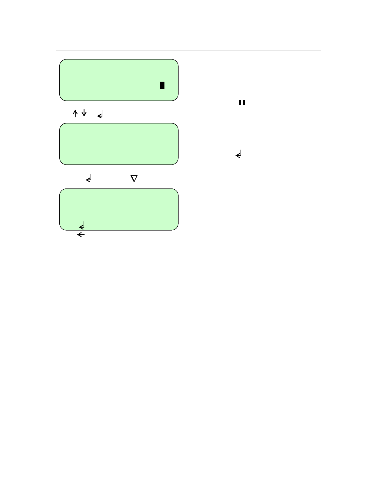
To insert a ‘pause’ into a program
Step 94.0ºC 00m30 max
Step 94.0ºC 00m30 max
-- Stage 2 ----------
-- Stage 2 ----------
Number cycles
Number cycles
Step 94.0ºC 00m30 max
Step 94.0ºC 00m30 max
[‘.’ to insert step ]
[‘.’ to insert step ]
[ , to edit ]
[ , to edit ]
Step 94.0ºC 00m30 max
Step 94.0ºC 00m30 max
-- Stage 2 ----------
-- Stage 2 ----------
Number cycles 0
Number cycles 0
Step 94.0ºC 00m30 max
Step 94.0ºC 00m30 max
[ CHANGE TO PAUSE ? ]
[ CHANGE TO PAUSE ? ]
[ Yes or No]
[ Yes or No]
-- Stage 2 ----------
-- Stage 2 ----------
Pause
Pause
---------------------
--------------------[ to insert step ]
[ to insert step ]
[ to delete step ]
[ to delete step ]
To insert a pause after an existing stage,
follow the steps for ins erting a stage a s
above.
Highlight the ‘Number cycles’ line then
press “Pause”
The prompt line will flash between
‘CHANGE TO PAUSE?’ and ‘YES or NO’.
Press “Enter” to insert a pause.
The stage number will then be highlighted
with ‘Pause’ as the only line.
23
Page 24
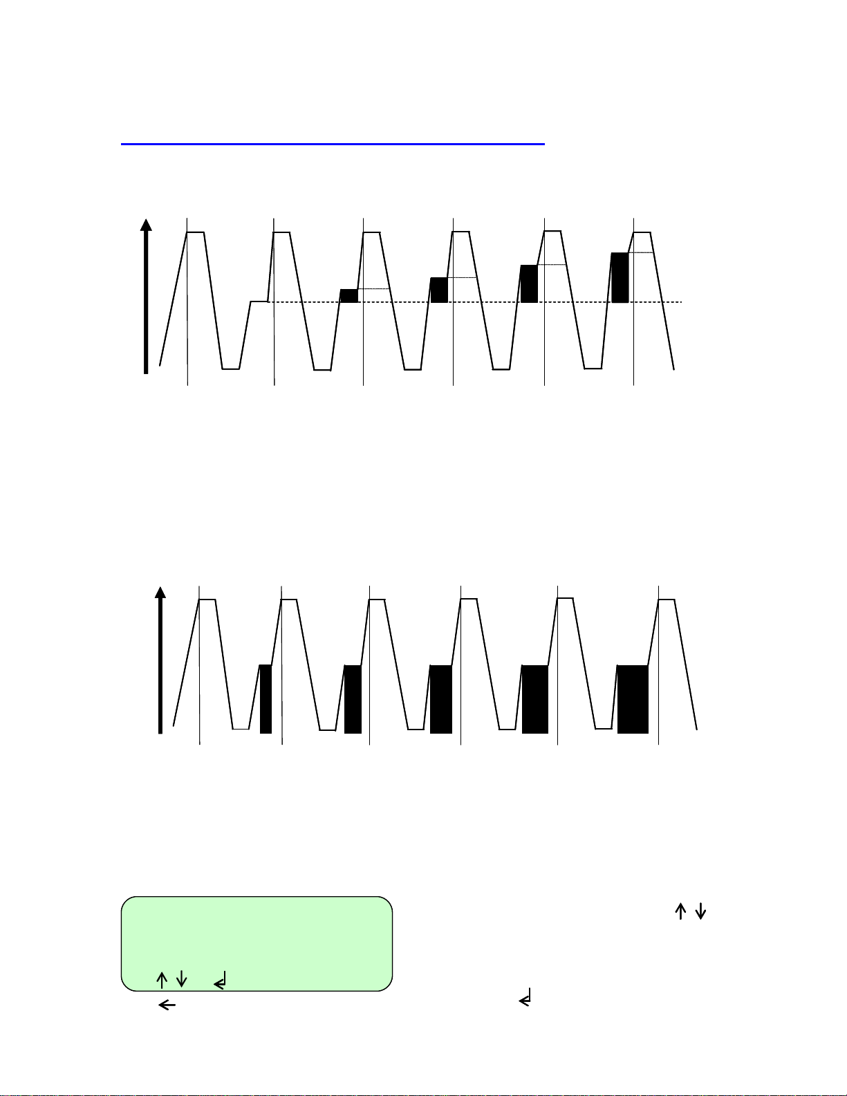
To program increment or decrement temperature or time.
Under normal circumstances, the Hold Temperature of all steps is constant. However, it is possible
to automatically increment or decrement the temperature of a specified step of a programme.
Temperature
Temperature
1
1
1
2
2
Cycle 1 Cycle 3Cycle 2 Cycle 4 Cycle 5
Cycle 1 Cycle 3Cycle 2 Cycle 4 Cycle 5
1
θ
3
3
2
2
1
1
3
3
θ+∂θ
2
2
1
1
3
3
θ+2∂θ
2
2
1
1
3
3
θ+3∂θ
2
2
1
1
3
3
θ+4∂θ
Temperature profile of incremented Hold Temperature at step 3 of each cycle
The Hold Temperature of the incremented/decremented step is the defined Hold Temperature plus
the summation of the increments/decrements. The first cycle is never incremented/decremented,
only subsequent cycles. If you select a decrement, the Hold Temperature is prevented from falling
below 4°C. If you select an increment, the Hold Temperature is prevented from rising above 99°C.
Similarly, under normal circumstances, the Hold Time of all steps is constant. However, it is
possible to automatically increment or decrement the duration of a specified step of a program.
1
1
1
1
1
1
1
1
1
1
1
1
3
3
3
3
3
3
3
3
3
3
Temperature
Temperature
2
2
Cycle 1 Cycle 3Cycle 2 Cycle 4 Cycle 5
Cycle 1 Cycle 3Cycle 2 Cycle 4 Cycle 5
t
2
2
t+∂t
2
2
2
2
t+2∂t t+3∂t t+4∂t
2
2
Temperature profile of incremented Hold Time at step 3 of each cycle
The Hold Time of the incremented/decremented step is the defined Hold Time plus the summation
of the increments/decrements. The first cycle is never incremented/decremented, only subsequent
cycles. If you select a decrement, the Hold Time is prevented from falling below one second.
Number cycles 30
Number cycles 30
Step 94.0ºC 00m30 max
Step 94.0ºC 00m30 max
Step 58.0ºC 00m30 max
Step 58.0ºC 00m30 max
[ , to edit ]
[ , to edit ]
[ to delete step ]
[ to delete step ]
[‘.’ to insert step ]
[‘.’ to insert step ]
Use the “Up Arrow” or “Down” Arrow”
keys to move to the step where you want
an increment or decrement temperature or
time.
24
Page 25
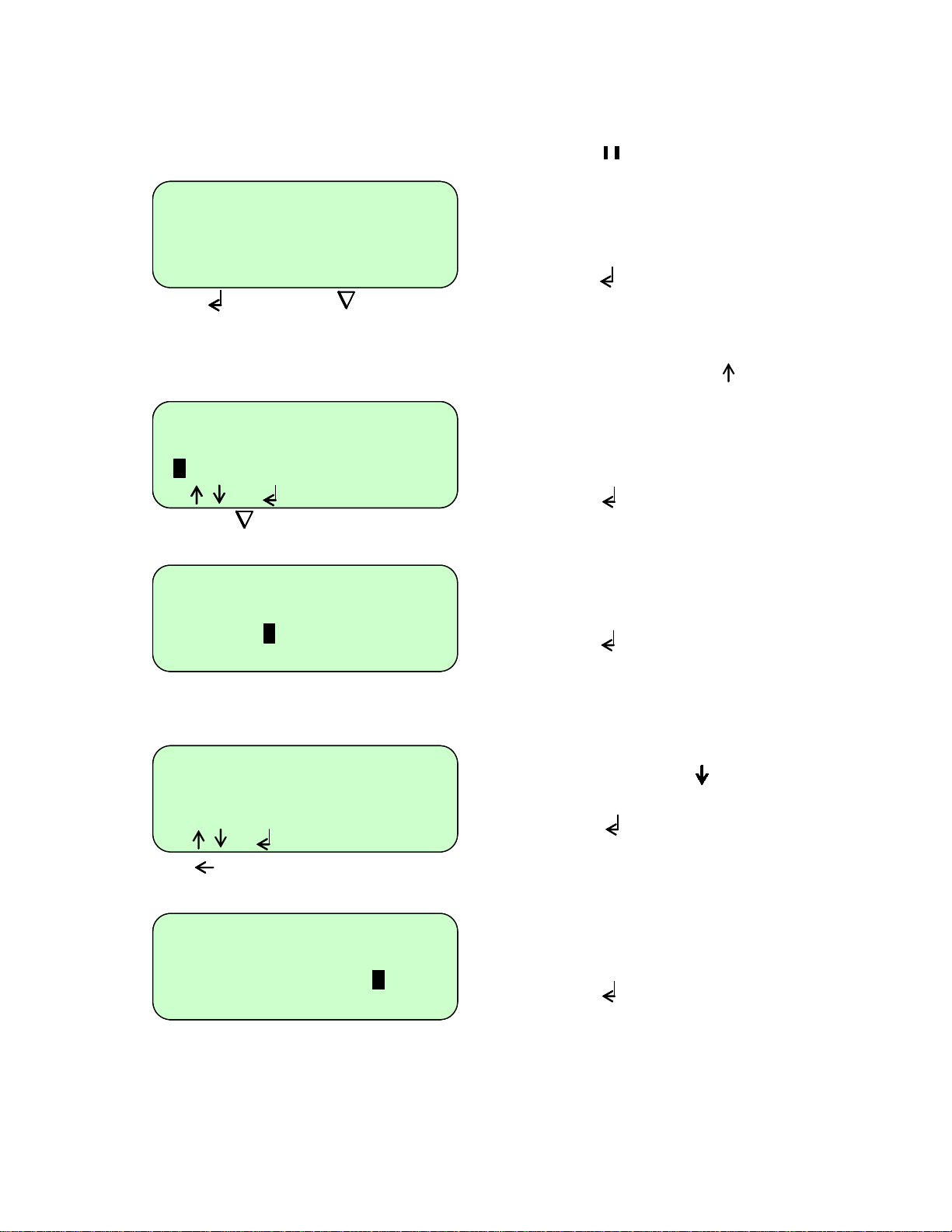
Number cycles 30
Number cycles 30
Number cycles 30
Step 94.0ºC 00m30 max
Step 94.0ºC 00m30 max
Step 94.0ºC 00m30 max
Step 58.0ºC 00m30 max
Step 58.0ºC 00m30 max
Step 58.0ºC 00m30 max
[ CHANGE STEP ? ]
[ CHANGE STEP ? ]
[ CHANGE STEP ? ]
[ YES OR NO ]
[ YES OR NO ]
[ YES OR NO ]
Number cycles 30
Number cycles 30
Number cycles 30
Number cycles 30
Step 94.0ºC 00m30 max
Step 94.0ºC 00m30 max
Step 94.0ºC 00m30 max
Step 94.0ºC 00m30 max
fst 55.0ºC 00m30 max
fst 55.0ºC 00m30 max
fst 55.0ºC 00m30 max
fst 55.0ºC 00m30 max
[ , to edit ]
[ , to edit ]
[ , to edit ]
[ , to edit ]
[ to save ]
[ to save ]
[ to save ]
[ to save ]
Number cycles 30
Number cycles 30
Number cycles 30
Step 94.0ºC 00m30 max
Step 94.0ºC 00m30 max
Step 94.0ºC 00m30 max
fst 65. ºC 00m30 max
fst 65. ºC 00m30 max
fst 65. ºC 00m30 max
[ edit temperature ]
[ edit temperature ]
[ edit temperature ]
Step 94.0ºC 00m30 max
Step 94.0ºC 00m30 max
fst 65.0ºC 00m30 max
fst 65.0ºC 00m30 max
lst 55.0ºC 00m30
lst 55.0ºC 00m30
[ , to edit ]
[ , to edit ]
[ to delete step ]
[ to delete step ]
[‘.’ to insert step ]
[‘.’ to insert step ]
Step 94.0ºC 00m30 max
Step 94.0ºC 00m30 max
Step 94.0ºC 00m30 max
fst 65.0ºC 00m30 max
fst 65.0ºC 00m30 max
fst 65.0ºC 00m30 max
lst 55.0ºC 1m30
lst 55.0ºC 1m30
lst 55.0ºC 1m30
[ edit time ]
[ edit time ]
[ edit time ]
[ . For hrs/mins ]
[ . For hrs/mins ]
[ . For hrs/mins ]
Press “Enter” to go into edit mode.
Press “Pause”
The prompt line will change to flash
between ‘CHANGE STEP?’ and ‘YES’ or
‘NO’.
Press “Enter”
The cursor will again move into the edit
mode.
Now press the “Up Arrow” key
The step will change to ‘fst’, meaning
“first”, and the software will in sert another
line after it entitled ‘lst’, meaning “last”.
Press “Enter” twice to go into edit
mode.
Use the “Alpha/numeric” keys to change
the values of the ‘fst’ line to the first
temperatures and/or times you require.
Press “Enter” after each field you
change.
You will exit ‘Edit Mode’ when you reach
the end of the line.
Use the “Down A rrow” key to move
onto the ‘lst’ line.
Press “Enter” to edit the step.
Use the “Alpha/numeric” keys to change
the values of the ‘lst’ line to the final
temperatures and/or times you require.
Press “Enter” for each field you
change.
You will exit ‘Edit Mode’ when you reach
the end of the line.
When you run the program it will
25
Page 26
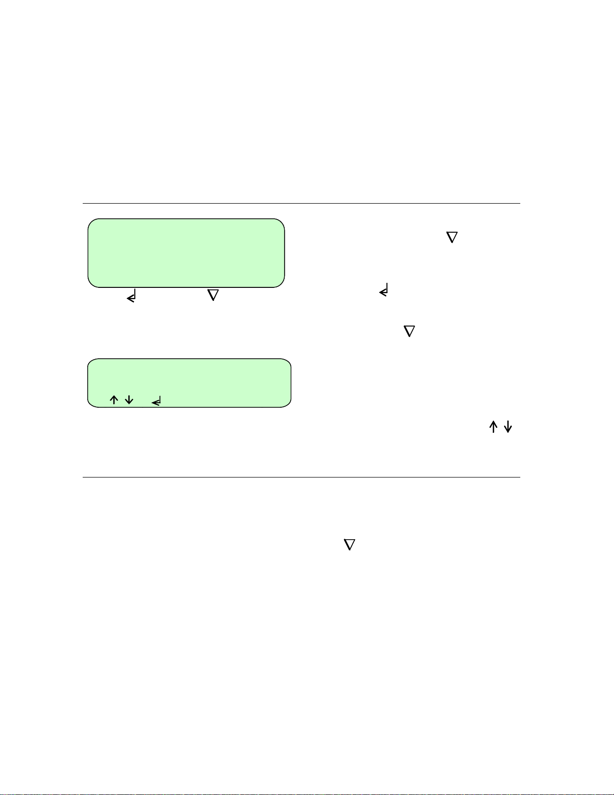
To save the program
d
-- Stage 1 ----------
-- Stage 1 ----------
Number cycles 10
Number cycles 10
Step 94.0ºC 00m30 max
Step 94.0ºC 00m30 max
[ SAVE ? ]
[ SAVE ? ]
[ Yes or No ]
[ Yes or No ]
Run metho
Run Program
View Program
View method
[ , to select ]
[ , to select ]
[ , to select ]
Stopping what you are doing
GEORGE [10]
GEORGE [10]
GEORGE [10]
automatica lly increment or decrement in
equal steps from the first time and/or
temperature to the last over the number of
cycles in the stage. For example: if the
first temperature is 65°C and the last
temperature is 55°C, over 30 cycles the
temperature will decrease 0.33°C each
cycle. Similarly, in the example shown, the
time would increase from 30 seconds to 1
minute 30 seconds in 2 second
increments.
A program can only be run once it has
been saved. Press the “End” key.
The prompt line will flash between 'SAVE?'
and 'YES or NO'.
Press “Enter” for ‘Yes’ to save the
changes you have made.
If you press “End” for ‘No’ then all the
changes you have made will be lost.
The program is now ready to run and will
be allocated with a unique “Speed dial”
number which can be used to rapidly
locate the program from the main start-up
screen.
Use the “Up Arrow” and “Down Arrow”
keys to scroll through the list of options.
At any time during programming the TCY ,
when you are satisfied with the program,
you can finish and accept what you have
done by first pressing the “End” key.
Then follow the instructions on screen. If
you are not sure, wait for the instructions
in the prompt line to scroll back to the first
line that you see.
26
Page 27
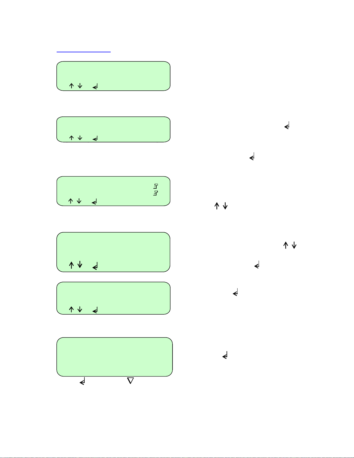
To run a program
d
Programs [0]
Methods [0]
Information
Information
Configuration
Configuration
[ , to select ]
[ , to select ]
Programs [7]
Methods [7]
Information
Information
Configuration
Configuration
[ , to select ]
[ , to select ]
* * New Methods ** []
* * New program ** []
2 STEP TEMPLATE 501
2 STEP 2
3 STEP TEMPLATE 502
3 STEP 3
[ , to select ]
[ , to select ]
DAVID 8 [D]
DAVID 8 [D]
DAVID 8 [D]
DONNA 7
DONNA 7
DONNA 7
[ , to select ]
[ , to select ]
[ , to select ]
Run metho
Run Program
View Program
View method
[ , to select ]
[ , to select ]
[ , to select ]
[ RUN PROGRAM ? ]
[ RUN METHOD ? ]
[ Yes or No ]
[ Yes or No ]
DONNA [7]
DONNA [7]
DONNA [7]
DONNA
DONNA
When the unit is switched on the display
will show this screen.
If known, type in the ‘Speed dial’ number
for the required program and press
“Enter” This will take you directly to the
required program.
If you do not know the ‘Speed dial’
number, press “Enter” to access the
list of stored programs.
Next either :
1. Scroll down to the required program
using the “Up Arrow” and “Down
Arrow” keys.
2. Or type the first letter of the program
name in the “New program” field; this
will then list all the program n ames
beginning with that letter. Use the “Up
Arrow” and “Down Arrow” keys
to select the required program.
Press “Enter” to accept
For example ‘Donna’.
To run the program, select ‘Run program’
and press "Enter"
A screen similar to this one will appear.
Press “Enter” to start the run.
27
Page 28
Cycle 4/30 56m08
Cycle 4/30 56m08
Cycle 4/30 56m08
Sample 58.0
Sample 58.0
Hold @ 58.0 º C 00m17
Hold @ 58.0
Hold @ 58.0
[ to STOP ]
[ to STOP ]
[ to STOP ]
[ to PAUSE ]
[ to PAUSE ]
[ to PAUSE ]
[ for info ]
[ for info ]
[ for info ]
Manual pause
Cycle 24/30 19m26
Cycle 24/30 19m26
Cycle 24/30 19m26
Sample 72.0
Sample 72.0
Hold @ 72.0
Hold @ 72.0
Hold @ 72.0
[ PAUSE ? ]
[ PAUSE ? ]
[ PAUSE ? ]
[ YES or NO ]
[ YES or NO ]
[ YES or NO ]
Cycle 24/30 19m26
Cycle 24/30 19m26
Cycle 24/30 19m26
Sample 72.0
Sample 72.0
Paused
Paused
[ to STOP ]
[ to STOP ]
[ to STOP ]
[ to CONTINUE ]
[ to CONTINUE ]
[ to CONTINUE ]
[ for info ]
[ for info ]
[ for info ]
Manual Stop
Cycle 28/30 10m39
Cycle 28/30 10m39
Cycle 28/30 10m39
Cycle 28/30 10m39
Sample 94.0
Sample 94.0
Sample 94.0
5.7 /S
Hold @ 94.0
Hold @ 94.0
Hold @ 94.0
Hold @ 94.0
[ STOP PROGRAM
[ STOP PROGRAM
[ STOP PROGRAM
[ STOP PROGRAM
[ YES or NO ]
[ YES or NO ]
[ YES or NO ]
[ YES or NO ]
º C
º C
º
C 00m17
C 00m17
º
º
C
C
C
º
º
º
C 00m10
C 00m10
C 00m10
º
º
º
º C
º C
º C
C
C
C
C
º
º
º
C 00m10
C 00m10
C 00m10
C 00m10
º
º
º
º
? ]
? ]
? ]
? ]
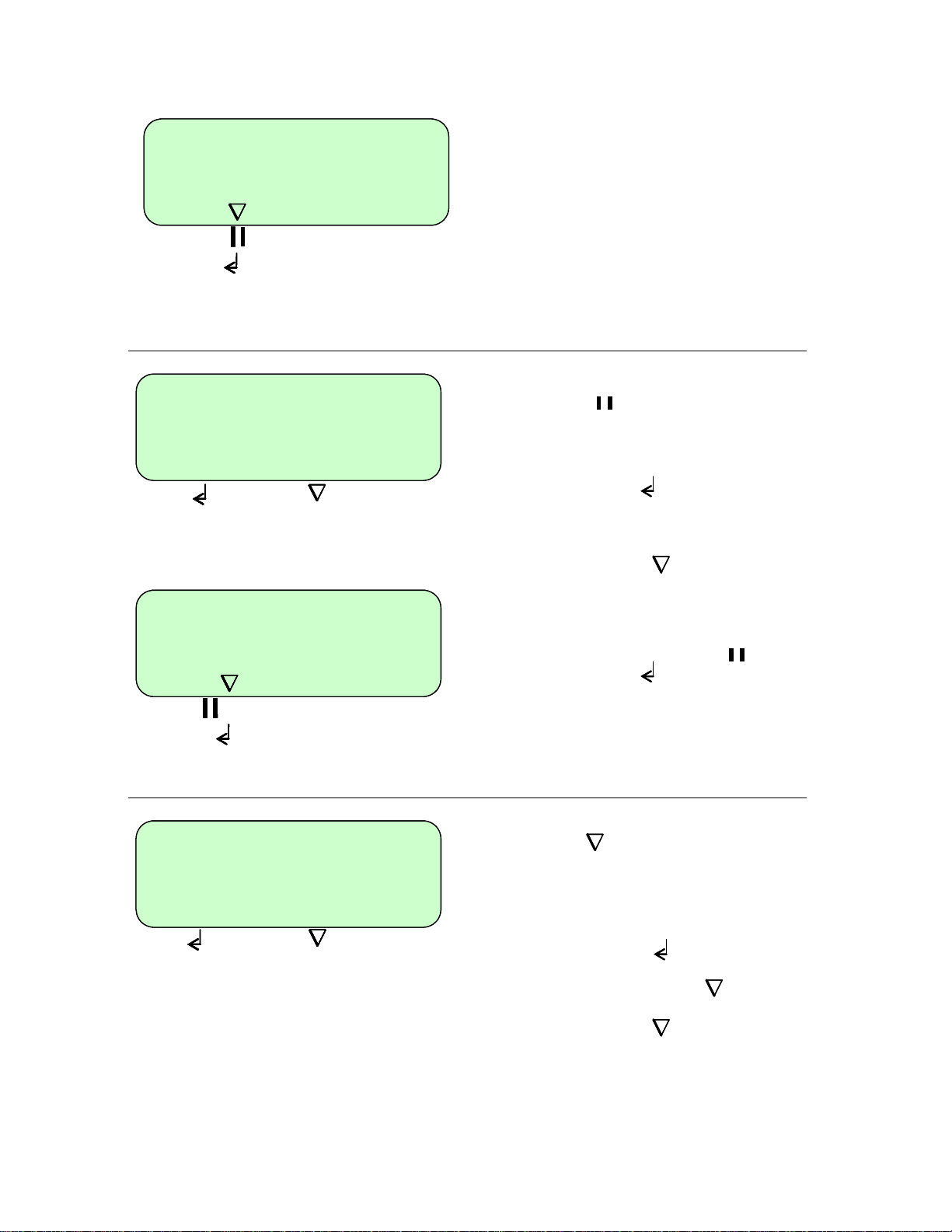
During the run the LCD screen will report:
1. The cycle number
2. The time remaining (counting down
in seconds)
3. The sample temperature (whether
holding or ramping)
4. Maximal ramp rate
5. The current step of the run
6. A count down of the hold time.
An example is shown here.
To pause a program while it is running,
press “Pause”
The run will continue but the prompt line
will alternate ‘PAUSE?’ and ‘YES or NO’
To confirm that you want the program to
pause press “Enter”
If you have pressed the “Pause” key by
mistake and you want the program to
continue, press “End”
The unit will emit a beeping sound while
paused.
To resume the run, press “Pause”
followed by “Enter” to continue.
To stop a program while it is running,
press “End”
º
The run will continue but the prompt line
will alternate ‘STOP PROGRAM?’ and ‘YES
or NO’
To confirm that you want to stop the
program press “Enter”
If you have pressed the “End” key by
mistake and you want the program to
continue, press “End” again.
When a program is stopped the unit will
emit a beeping sound and the original
program screen will appear.
28
Page 29
Program Information
-
2
-
0
2
m
.
Heated Lid on
Heated Lid on
Status ramping
Status ramping
[ to exit ]
[ to exit ]
DONNA
DONNA
8. Information
Programs [0]
Programs [0]
Information
Information
Configuration
Configuration
[ , to select ]
[ , to select ]
Block 20x0.5ml
Block Type: 96x0.
Block s/n
Block id
Unit s/n
Unit s/n C4C123456
S/w version 14.zz
S/w version 6
H/w version 01
H/w version 2.ZZ
Comms
Comms
Unit cycles 624
Unit cycles 624
Block cycles 69
Block cycles 69
address 1
address 1
139160
123456789
GP0000
zz
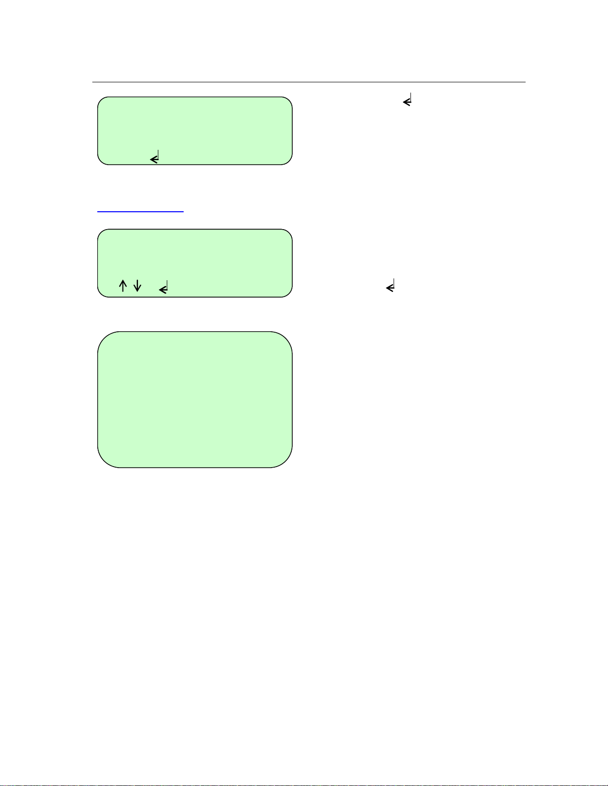
Pressing “Enter” while a program is
running will give information about the
current run including which program is
actually running and the unit status e.g.
holding or ramping.
An example is shown here.
The Information field on the front screen
contains all the unit-specific information
such as serial number and software
version.
Press “Enter” to access the unit
information.
l
1
The complete list is displayed here.
Note that the “Comms address” must be
unique for each unit if more than one TCY
is linked to a PC
29
Page 30
9. Configuration
Warning! The Configuration software should only be accessed by designated personnel, as some
parameters can be changed or may be lost when using it.
Programs [0]
Methods [0]
Information
Information
Configuration
Configuration
[ , to select ]
[ , to select ]
Password pad
Password pad
[ to accept ]
[ to accept ]
[ to exit ]
[ to exit ]
Program defaults
Settings
Settings
Passwords
Passwords
Format memory
Controller reset
Self-calibrate
Settings
Program defaults
Settings
Settings
Passwords
Settings
Format memory
Passwords
Controller reset
Self-calibrate
Program defaults
Settings
CONFIGURATION
CONFIGURATION
Passwords
Passwords
Format memory
Controller reset
Self-Calibrate
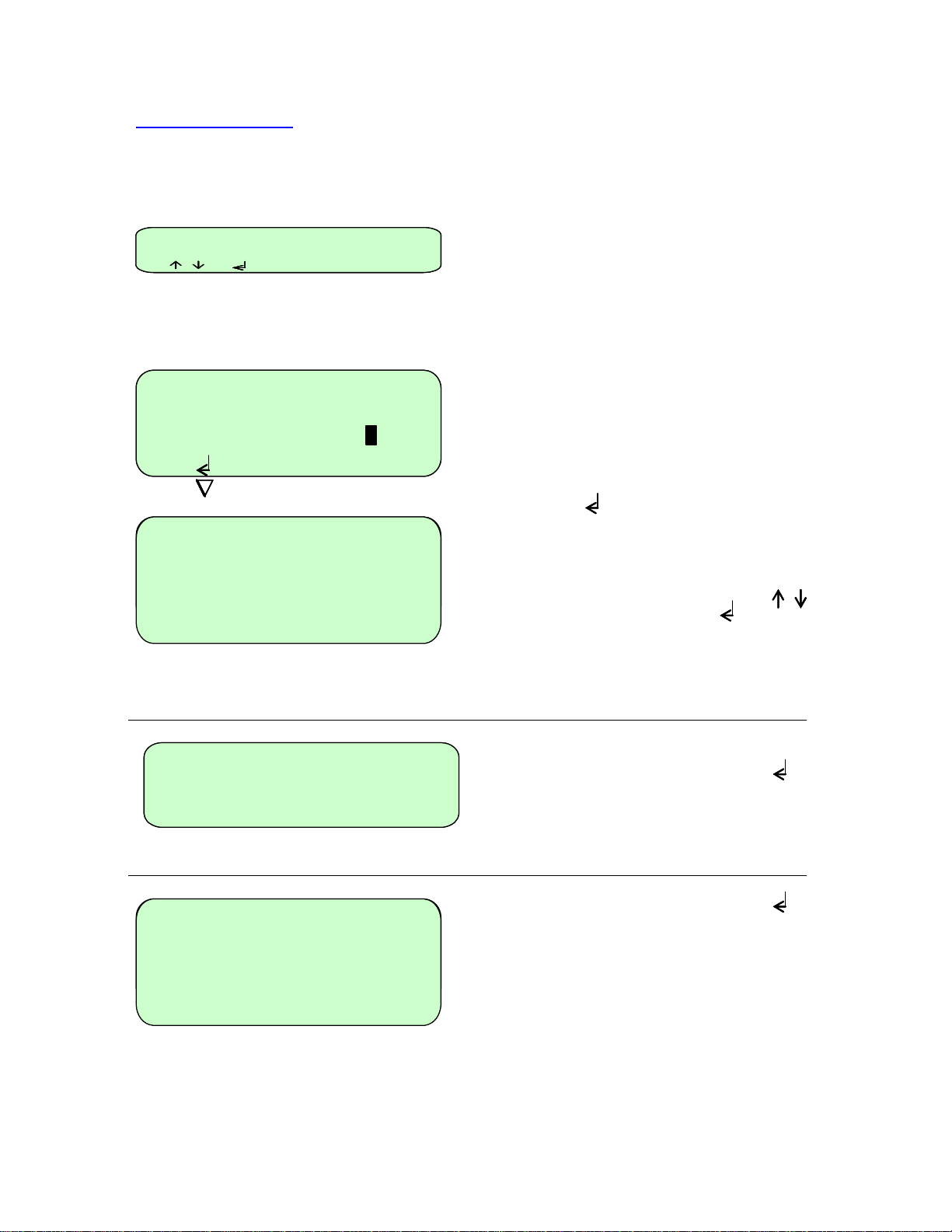
The Configuration field on the front screen
allows a system administrator access to
set up all the default settings for the
programs, time and date settings and to
change and remove passwords.
Access to the ‘Configuration’ set up is
password protected.
Default admin passwords is 1234
To enter configuration, use the alpha keys
to type in ‘pad’
Press “Enter”
There are a number of options which can
be changed; these are listed here.
Use the “Up Arrow” and “Down Arrow”
keys to select then press “Enter” to
access any of the options. Each option is
discussed in detail below.
Highlight ‘Settings’ then press “Enter”
Highlight ‘Settings’ then press “Enter”
30
Page 31
d
d
1920
Set date xx/xx/xx
Set date xx/xx/xx
Set date xx/xx/xx
Set time
Set time xx:xx
Set time xx:xx
Auto restart on
Date format
Date format
Auto restart on
Auto restart on
Beeper on
Beeper on
Beeper on
Coms address 1
address 1
Coms
Coms
Coms speed
Coms
Coms
[ , to select ]
[ , to select ]
[ , to select ]
Passwords
Settings
Program defaults
Settings
Passwords
Passwords
Format memory
Controller reset
Self-calibrate
** Admin passwd **
** Admin passwd **
DONNA
DONNA
GEORGE
GEORGE
[ , to select ]
[ , to select ]
Password
Password
Password
Password
Confirm
Confirm
Confirm
Confirm
[ to accept ]
[ to accept ]
[ to accept ]
[ to accept ]
** Admin passwd **
** Admin passwd **
DONNA
DONNA
GEORGE
GEORGE
[ DEL PASSWORD ? ]
[ DEL PASSWORD ? ]
[ YES NO ]
[ YES NO ]
address 1
speed 4800
speed 4800
ADMIN PASSWORD
ADMIN PASSWORD
ADMIN PASSWORD
ADMIN PASSWORD
xx:xx
my
my
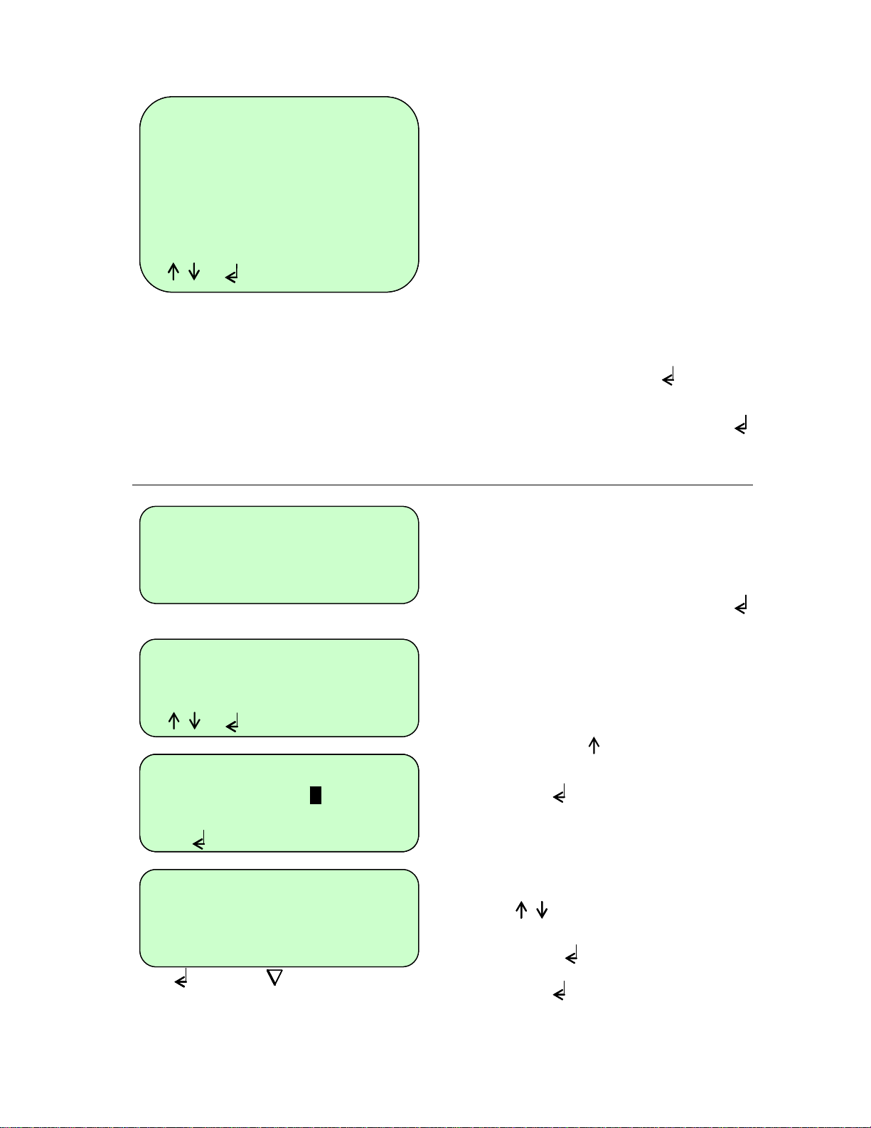
The complete list of settings is given here.
Auto restart “on” will allow the unit to
restart from where it left off should there
be a power failure and the power returns.
The “Comms address” refers to the
0
location of a unit in a daisy chain and
must be unique if there are several units
linked to each other.
The optimum “Coms speed” is set at
19200. When using control software,
ensure all TCY’s are set to the same value.
Edit any line as described for ‘Program
defaults’ above. Press “Enter” to
accept the new value.
When you have finished, press the “Enter”
key to go back to the ‘Configuration’
menu.
The ‘Passwords’ function allows the
administrator to change the ‘Admin
password’ (which allows access to
Configuration) and also to delete any
passwords associated with programs.
Highlight ‘Passwords’ then press “Enter”
The screen will appear as opposite.
We suggest that you change the ‘Admin
password’ at this stage in order to protect
the configuration settings.
Use the “Up Arrow” key to highlight
‘Admin passwd’
Press “Enter” and type in the new
password. Repeat to confirm and accept.
The screen will go back to the
‘Configuration’ menu.
To delete a password associated with a
program, use the “Up Arrow” and “Down
Arrow” keys to highlight the
program.
Press “Enter”
Press “Enter” again to delete the
password.
31
Page 32
Controller reset
Settings
Program defaults
Settings
Passwords
Passwords
Format memory
Self-calibrate
Controller reset
Format Memory
CONTROLLER RESET
This will delete
This will delete
all programs
all methods
[ SURE ? ]
[ SURE ? ]
[ YES NO ]
[ YES NO ]
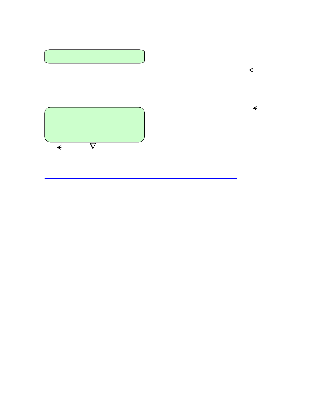
The ‘Format memory’ will delete all saved
programs from the unit.
Highlight ‘Format memory’ then press
“Enter”
To delete all the programs, press “Enter”
Set ADMIN PASSWORD to 1234.
10. Notes on transferring protocols from other thermal TCYs
The TCY heats at over 3.6°C/s and provides the highest levels of temperature uniformity. Many
slower machines have historically begun the countdown on hold times before the set temperature
is reached in order to avoid any overshooting in sample temperature. The slower the heating rate
the more significant the loss in hold time, i.e. if a 30 second hold time is set at 55°C then perhaps
5 to 10s will be lost in between the start of the time countdown and actually reaching the set
temperature. The overall effect of this method of control is that your sample, if cooling from a
higher temperature, is subjected to an environment with an elevated temperature compared to the
target temperature for a significant part of the hold time.
The TCY provides the user with ‘what-you-program-is what-you-get’. Due to the rapid and
responsive nature of the Peltier heating system, the time between the timer countdown initiating
and actually reaching the set temperature has been reduced to as little as 1s. This ensures that
the sample is only subjected to the exact temperature required.
Taking the above into consideration it must therefore be noted that care must be taken when reoptimizing protocols from a slower machine.
Trouble Shooting
1. The optimum annealing temperature may in fact be higher than the set temperature used
in the slower machine. Try increasing it by 1 or 2°C.
2. The hold time can be reduced once the optimum temperature has been found. Try
reducing it by 5 to 10s.
32
Page 33
11. User maintenance
Cleaning your TCY
The heating/cooling block, including wells and flat surfaces, should be cleaned regularly to ensure
optimum heat transfer to the samples. Always clean the block if there has been a spillage. Use a
cloth or cotton buds dipped in a fresh, 50:50 water/isopropanol solution and make sure that no
deposits are left in the wells.
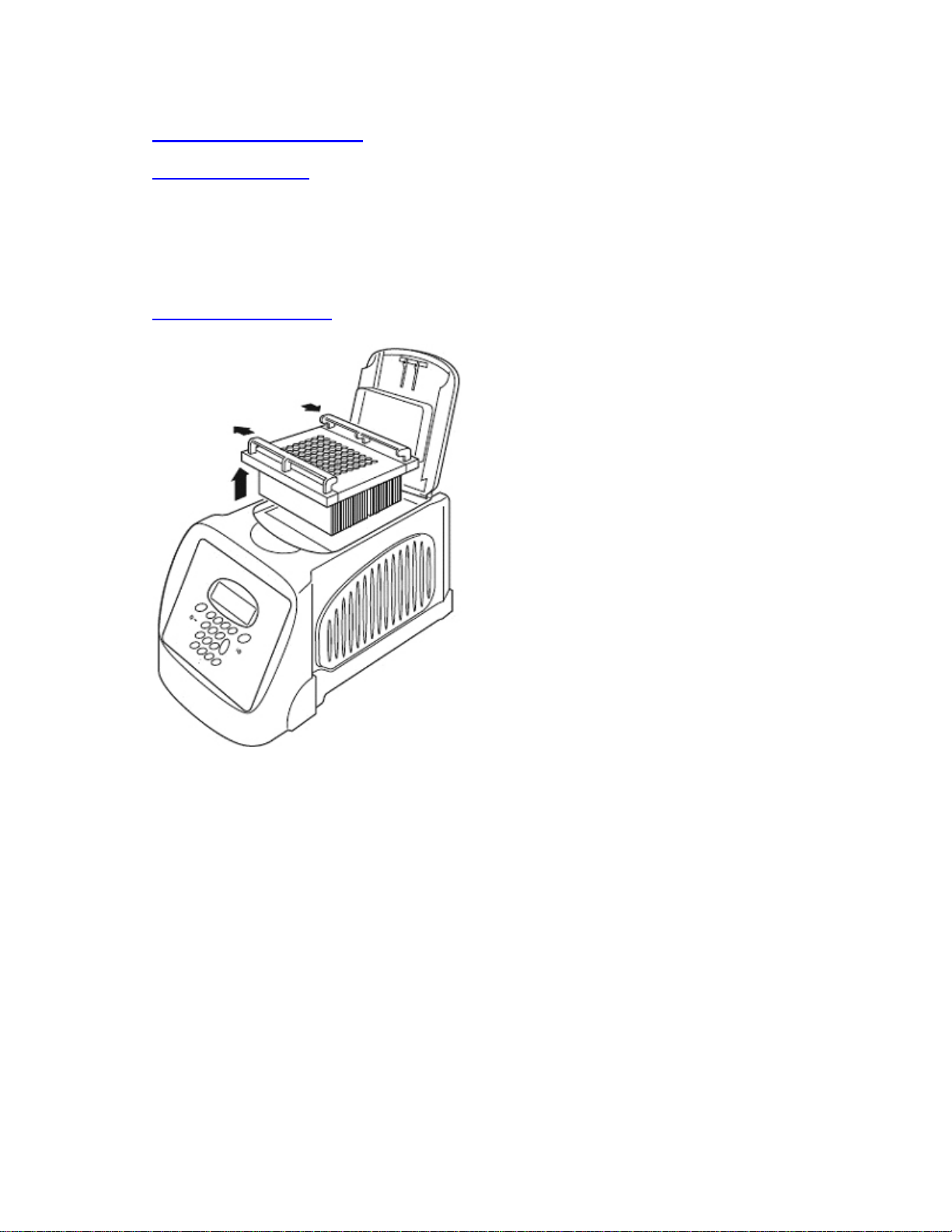
Heater Block removal
Before cleaning your unit, disconnect from the power supply and allow it to cool to below 50°C.
Slide the quick release handles in the
direction of the arrows indicated and lift the
block assembly out of the unit.
Never lift or carry the block by one quick
release handle, always use both handles or
support the block from underneath.
When re-fitting the block, or fitting a new one,
slide the quick release handles in the
opposite direction to lock the assembly into
the unit.
Open or closed padlock symbols are printed
on the quick release handles for easy
reference.
The outer case of the TCY can be cleaned with a cloth dipped in water or ethanol (methanol or
formaldehyde can also be used). No part of the case or cover should be immersed in the solvents.
Do not use aggressive solvents such as acetone, or abrasive cleaners.
33
Page 34

12. Some frequently asked questions
Q1 What is the ‘Pause’ function at the start of the program used for?
A1
Q2 Why do you have to press some keys twice to make the unit do what you want it to
A2
Q3 What is ‘Hot Start’?
A3
Q4 What is the incremental function? (See pages 29-31).
A4
Q5 The heat-up ramp-rate in the specification is 3.6°C/second yet I can only manually set
A5
Some users prefer to preheat the heated lid before placing the samples into the
unit. The pause feature is used to stop the unit after the 4 minute heated lid
preheat step. It will also sound an audible alarm indicating that the machine is
ready for the sample tubes or plate to be added. Pressing the “Pause” key
followed by the “Enter” key will commence the remaining program.
do.?
With many of the program features there is a fail-safe function which asks if
you are sure you want to perform a particular action. You are required to press
one key to select a function followed by a second to accept it.
A “hot start” is used for reducing non-specific product formation during the
first cycle of amplification. The ‘Hot Start’ programming step is used to pause
the instrument at a specific temperature, typically around 70ºC, after the initial
template denaturation. The reason is to allow the manual addition of
unmodified Taq DNA polymerase which may loose activity if added during the
initial 5min denaturation. Heat-activated Taq or Hot Start enzymes do not
require this step.
Incremental timing and temperature are used to increase or decrease either the
time or temperature incrementally over the number of cycles in a stage.
Incrementation of extension time is used with ‘Long PCR’ which is when large
template fragments are to be amplified (e.g. 27kb lambda DNA, 40kb genomic
DNA).
Decremental temperature is used for protocols such as ‘Touchdown PCR’
where one starts with a high annealing temperature in the first cycle and
gradually decreases the temperature over the number of cycles in the stage.
This ensures that only the specific product is amplified.
it to 2.0°C/second. Why is this?
If you set the ramp-rate to max the block will heat at 3.6°C/second the unit sets
its own control parameters. If you program a ramp-rate the control parameters
reduce the ramp-rate. This is a feature of the software and not the actual ramprate.
34
Page 35

13. Additional information
Brief fault finding notes and a list of replacement parts are given in this section.
Do Not Remove the outer cover or dismantle this unit! There are no user
serviceable parts within.
Fault Finding
Should you encounter problems with your TCY contact Omega Flow Engineering for assistance.
Please include details of the fault observed and remember to return the unit in its original packing.
Omega Engineering accepts no responsibility for damage to units which are not properly packed
for shipping: if in doubt, contact your supplier, giving the full serial number of the unit and software
version number (shown when the unit is first switched on).
Fuses
If neither the power light nor display on the front panel is lit, one of the two fuses may have blown.
Check that there is no external cause, such as a faulty plug or lead. Check both fuses and replace
the faulty fuse with a new one of the correct value (fuse values are given on the label next to the
power inlet). Note that fuses should only be replaced by a qualified electrician.
The holder for the two fuses is built into the power input socket. First remove the power cable and
then gently prise the fuse drawer open with a flat-bladed screwdriver or similar tool.
Each fuse can be removed by using the screwdriver as a lever.
Exchange the faulty fuse in the fuse holder for a working fuse of the correct value. Finally, replace
the fuse drawer in the fuse compartment and push the drawer shut.
Fuses which blow repeatedly indicate a serious fault and you should return the unit to your
supplier for repair.
The heated lid over-temperature cut-out
The heated lid is fitted with an independent circuit to protect it from overheating. In the unlikely
event of an over-temperature problem with the lid, the unit is fitted with a thermal fuse which will
remove power to the heater plate should the maximum temperature be exceeded.
Insulation testing
This equipment is fitted with RFI suppression circuitry. Any check of the electrical insulation by
means of high voltage dielectric testing (for example as in BS EN 61010-1) must be carried out
using only a DC voltage.
This unit contains semiconductor components which may be damaged by electric field effects.
Interchangeable blocks
The block can be removed and replaced by another of the same sort or of a different sort. The
software will register the change and set up the unit for the new block.
Before removing the block, disconnect from the power supply and allow it to cool to below 50℃.
35
Page 36
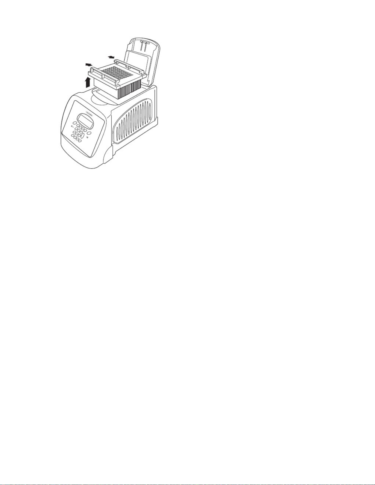
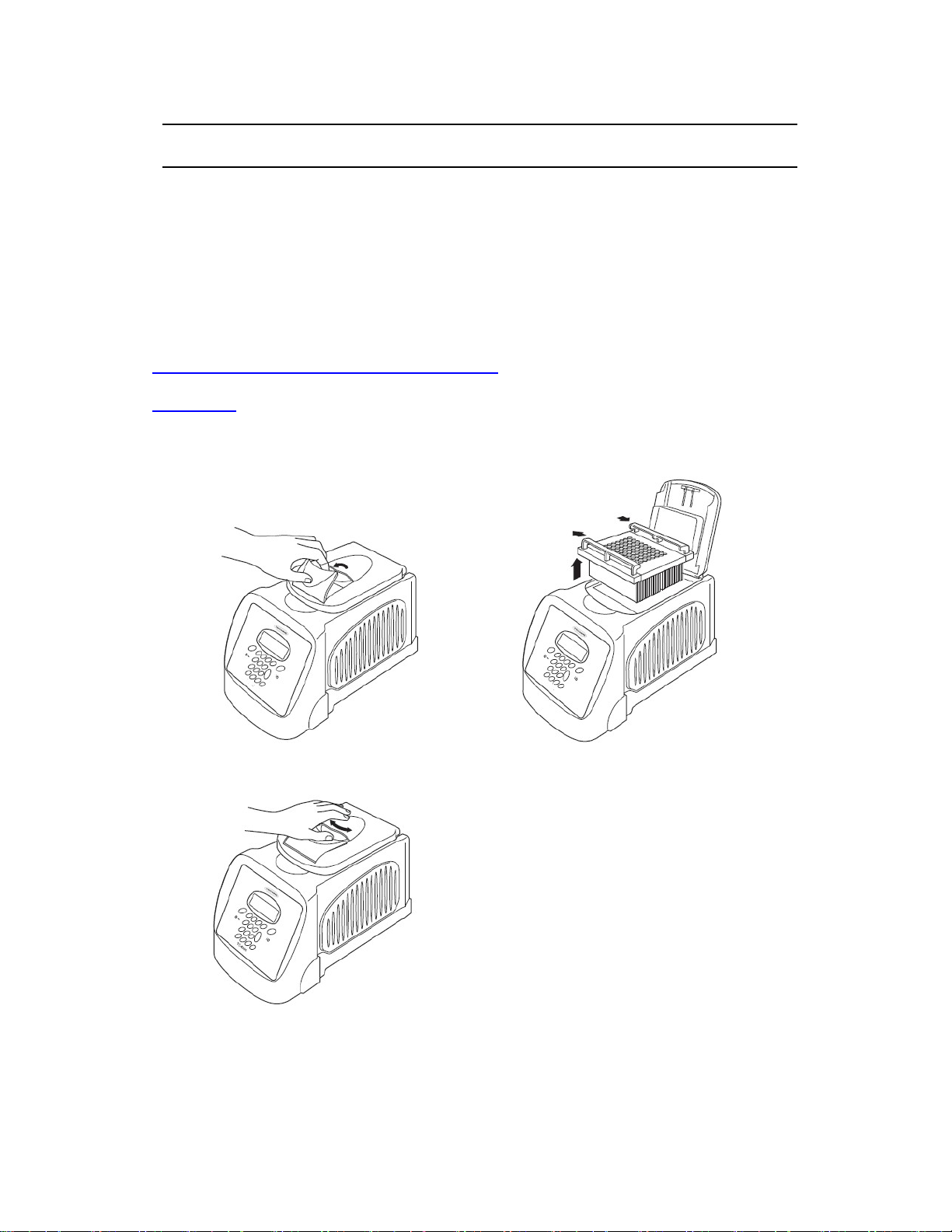
Slide the quick release handles in the direction of
the arrows indicated and lift the block assembly out
of the unit.
Never lift or carry the block by one quick release
handle, always use both handles or support the
block from underneath.
When re-fitting the block, or fitting a new one, slide
the quick release handles in the opposite direction
to lock the assembly into the unit.
Open or closed padlock symbols are printed on the
quick release handles for easy reference.
If you have fitted a flat block for slide applications, you must set the heated lid to OFF.
36
Page 37

WARRANTY/DISCLAIMER
OMEGA ENGINEERING, INC. warrants this unit to be free of defects in materials and workmanship for a
period of 36 months from date of purchase. OMEGA’s WARRANTY adds an additional one (1) month
grace period to normal three (3) year product warranty to cover handling and shipping time. This
ensures that OMEGA’s customers receive maximum coverage on each product.
If the unit malfunctions, it must be returned to the factory for evaluation. OMEGA’s Customer Service
Department will issue an Authorized Return (AR) number immediately upon phone or written request.
Upon examination by OMEGA, if the unit is found to be defective, it will be repaired or replaced at no
charge. OMEGA’s WARRANTY does not apply to defects resulting from any action of the purchaser,
including but not limited to mishandling, improper interfacing, operation outside of design limits,
improper repair, or unauthorized modification. This WARRANTY is VOID if the unit shows evidence of
having been tampered with or shows evidence of having been damaged as a result of excessive corrosion;
or current, heat, moisture or vibration; improper specification; misapplication; misuse or other operating
conditions outside of OMEGA’s control. Components in which wear is not warranted, include but are not
limited to contact points, fuses, and triacs.
OMEGA is pleased to offer suggestions on the use of its various products. However,
OMEGA neither assumes responsibility for any omissions or errors nor assumes liability for any
damages that result from the use of its products in accordance with information provided by
OMEGA, either verbal or written. OMEGA warrants only that the parts manufactured by the
company will be as specified and free of defects. OMEGA MAKES NO OTHER WARRANTIES OR
REPRESENTATIONS OF ANY KIND WHATSOEVER, EXPRESSED OR IMPLIED, EXCEPT THAT OF
TITLE, AND ALL IMPLIED WARRANTIES INCLUDING ANY WARRANTY OF MERCHANTABILITY
AND FITNESS FOR A PARTICULAR PURPOSE ARE HEREBY DISCLAIMED. LIMITATION OF
LIABILITY: The remedies of purchaser set forth herein are exclusive, and the total liability of
OMEGA with respect to
emnification, strict liability or otherwise, shall not exceed the purchase price of the
ind
co mpone nt upon which liab ility is based. In no event s hall OMEGA be liable for
consequential, incidental or special damages.
CONDITIONS: Equipment sold by OMEGA is not intended to be used, nor shall it be used: (1) as a “Basic
Component” under 10 CFR 21 (NRC), used in or with any nuclear installation or activity; or (2) in medical
applications or used on humans. Should any Product(s) be used in or with any nuclear installation or
activity, medical application, used on humans, or misused in any way, OMEGA assumes no responsibility
as set forth in our basic WARRANTY/DISCLAIMER language, and, additionally, purchaser will indemnify
OMEGA and hold OMEGA harmless from any liability or damage whatsoever arising out of the use of the
Product(s) in such a manner.
this order, whether based on contract, warranty, negligence,
RETURN REQUESTS/INQUIRIES
Direct all warranty and repair requests/inquiries to the OMEGA Customer Service Department. BEFORE
RETURNING ANY PRODUCT(S) TO OMEGA, PURCHASER MUST OBTAIN AN AUTHORIZED RETURN
(AR) NUMBER FROM OMEGA’S CUSTOMER SERVICE DEPARTMENT (IN ORDER TO AVOID
PROCESSING DELAYS). The assigned AR number should then be marked on the outside of the return
package and on any correspondence.
The purchaser is responsible for shipping charges, freight, insurance and proper packaging to prevent
breakage in transit.
FOR WARRANTY
following information available BEFORE
contacting OMEGA:
1. Purchase Order number under which the product
was PURCHASED,
2. Model and serial number of the product under
warranty, and
3. Repair instructions and/or specific problems
relative to the product.
OMEGA’s policy is to make running changes, not model changes, whenever an improvement is possible. This affords
our customers the latest in technology and engineering.
OMEGA is a registered trademark of OMEGA ENGINEERING, INC.
© Copyright 2009 OMEGA ENGINEERING, INC. All rights reserved. This document may not be copied, photocopied,
reproduced, translated, or reduced to any electronic medium or machine-readable form, in whole or in part, without the
prior written consent of OMEGA ENGINEERING, INC.
RETURNS, please have the
FOR NON-WARRANTY REPAIRS,
for current repair charges. Have the following
information available BEFORE contacting OMEGA:
1. Purchase Order number to cover the COST
of the repair,
2. Model and serial number of the product, and
3. Repair instructions and/or specific problems
relative to the product.
consult OMEGA
Page 38

Where Do I Find Everything I Need for
Process Measurement and Control?
OMEGA…Of Course!
Shop online at omega.com
SM
TEMPERATURE
Thermocouple, RTD & Thermistor Probes, Connectors, Panels & Assemblies
Wire: Thermocouple, RTD & Thermistor
Calibrators & Ice Point References
Recorders, Controllers & Process Monitors
Infrared Pyrometers
PRESSURE, STRAIN AND FORCE
Transducers & Strain Gages
Load Cells & Pressure Gages
Displacement Transducers
Instrumentation & Accessories
FLOW/LEVEL
Rotameters, Gas Mass Flowmeters & Flow Computers
Air Velocity Indicators
Turbine/Paddlewheel Systems
Totalizers & Batch Controllers
pH/CONDUCTIVITY
pH Electrodes, Testers & Accessories
Benchtop/Laboratory Meters
Controllers, Calibrators, Simulators & Pumps
Industrial pH & Conductivity Equipment
DATA ACQUISITION
Data Acquisition & Engineering Software
Communications-Based Acquisition Systems
Plug-in Cards for Apple, IBM & Compatibles
Datalogging Systems
Recorders, Printers & Plotters
HEATERS
Heating Cable
Cartridge & Strip Heaters
Immersion & Band Heaters
Flexible Heaters
Laboratory Heaters
ENVIRONMENTAL
MONITORING AND CONTROL
Metering & Control Instrumentation
Refractometers
Pumps & Tubing
Air, Soil & Water Monitors
Industrial Water & Wastewater Treatment
pH, Conductivity & Dissolved Oxygen Instruments
M-5379/0114
 Loading...