

Page 1
User’s Guide
Shop online at
omega.com
e-mail: [email protected]
For latest product manuals:
omegamanual.info
TBE-10 Series
Turbidity Transmitters
Page 2

OMEGAnet®Online Service Internet e-mail
omega.com [email protected]
Servicing North America:
U.S.A.: Omega Engineering, Inc., One Omega Drive, P.O. Box 4047
ISO 9001 Certified Stamford, CT 06907-0047 USA
Canada: 976 Bergar
Laval (Quebec), Canada H7L 5A1
Toll-Free: 1-800-826-6342 TEL: (514) 856-6928
FAX: (514) 856-6886 e-mail: [email protected]
For immediate technical or application assistance:
U.S.A. and Canada: Sales Service: 1-800-826-6342/1-800-TC-OMEGA
Customer Service: 1-800-622-2378/1-800-622-BEST
Engineering Service: 1-800-872-9436/1-800-USA-WHEN
Mexico: En Español: 001 (203) 359-7803 FAX: (001) 203-359-7807
®
®
®
Servicing Europe:
Benelux: Managed by the United Kingdom Office
Czech Republic: Frystatska 184
733 01 Karviná, Czech Republic
Toll-Free: 0800-1-66342 TEL: +420-59-6311899
FAX: +420-59-6311114 e-mail: [email protected]
France: Managed by the United Kingdom Office
Toll-Free: 0800 466 342 TEL: +33 (0) 161 37 29 00
FAX: +33 (0) 130 57 54 27 e-mail: [email protected]
Germany/Austria: Daimlerstrasse 26
D-75392 Deckenpfronn, Germany
Toll-Free: 0 800 6397678 TEL: +49 (0) 7059 9398-0
FAX: +49 (0) 7056 9398-29 e-mail: [email protected]
United Kingdom: OMEGA Engineering Ltd.
ISO 9001 Certified One Omega Drive, River Bend Technology Centre, Northbank
Irlam, Manchester M44 5BD England
Toll-Free: 0800-488-488 TEL: +44 (0)161 777-6611
FAX: +44 (0)161 777-6622 e-mail: [email protected]
It is the policy of OMEGA Engineering, Inc. to comply with all worldwide safety and EMC/EMI
regulations that apply. OMEGA is constantly pursuing certification of its products to the European New
Approach Directives. OMEGA will add the CE mark to every appropriate device upon certification.
The information contained in this document is believed to be correct, but OMEGA accepts no liability for any
errors it contains, and reserves the right to alter specifications without notice.
WARNING: These products are not designed for use in, and should not be used for, human applications.
Page 3

Table of Contents
Safety Definitions and Information ............................................................................................................... 5
Unpacking ..................................................................................................................................................... 5
Quick Setup Guide......................................................................................................................................... 6
Choose Location ........................................................................................................................................ 6
Install Electrical Connection ...................................................................................................................... 6
Position Sensor ......................................................................................................................................... 6
Connect ..................................................................................................................................................... 6
Product Description ...................................................................................................................................... 7
Principle of Operation ............................................................................................................................... 7
Features .................................................................................................................................................... 7
Technical Specifications ............................................................................................................................ 8
Mechanical ............................................................................................................................................ 8
Performance/Electrical ......................................................................................................................... 8
Preliminaries ................................................................................................................................................. 8
Standard Shipments .................................................................................................................................. 8
Unpack and Check Contents ..................................................................................................................... 8
Electrical Connections ................................................................................................................................... 9
Operation .................................................................................................................................................... 10
Applying Power ........................................................................................................................................... 10
Test Output ............................................................................................................................................. 10
3
Page 4

Installation .................................................................................................................................................. 10
Deadleg ................................................................................................................................................... 11
Installation Site ....................................................................................................................................... 11
Vertical ................................................................................................................................................ 11
Horizontal ............................................................................................................................................ 11
Straight Sections ................................................................................................................................. 11
Installations Not Recommended ........................................................................................................ 11
Clamp Connection Gasket ....................................................................................................................... 11
Connect ................................................................................................................................................... 11
Calibration Verification or Test with Your Samples .................................................................................... 12
Calibration Procedure ................................................................................................................................. 13
Sensor Offset and Span Calibration ............................................................................................................ 14
4
Page 5

Warning!
Caution
Notice
Caution
Safety Definitions and Information
Do not attempt to install or use your Omega product until you have read the safety instructions in this
section. Save this manual and keep it in an easily accessible place.
Warning means that failure to follow this safety statement may result in extensive product damage,
serious personal injury, or death.
Caution means that failure to follow this safety statement may result in minor or moderate personal
injury, property or equipment damage.
Notice is a statement that informs about installation, operation, maintenance, performance issues, or
general tips which are important but do not create a hazard or safety concern.
Unpacking
1. Separate the TBE-10 device from packaging materials and check for any visual signs of damage.
If you determine there has been damage caused by shipping, file a claim with the shipping
company. If the sensor appears to have been improperly assembled or does not operate
properly, return it for replacement or repair (see Limited Warranty information at the end of
this manual).
2. Carefully remove all items from the shipping package and compare the contents to those listed
on the shipping documents. If there is a discrepancy, contact the manufacturer.
Before connecting or using the TBE-10 sensor, read this manual.
5
Page 6

Caution
Notice
Quick Setup Guide
As with any precision-engineered device, always use the TBE-10 Turbidity Transmitter in accordance
with the manufacturer’s instructions.
Choose Location
The best location to install the TBE-10 sensor is to a tee or saddle in the process line.
Install Electrical Connection
Attach the five-pin electrical cable to the sensor and tighten the threaded cord grip.
Position Sensor
Install the sensor horizontally in the process line preferably with the electrical connection facing
the floor (see Figure 2, page 15).
Connect
Connect the opposite end of the electrical cable to PLC, DCS, or data logger.
In the following manual, you will find complete connection, operating, set-up, and maintenance
instructions.
6
Page 7
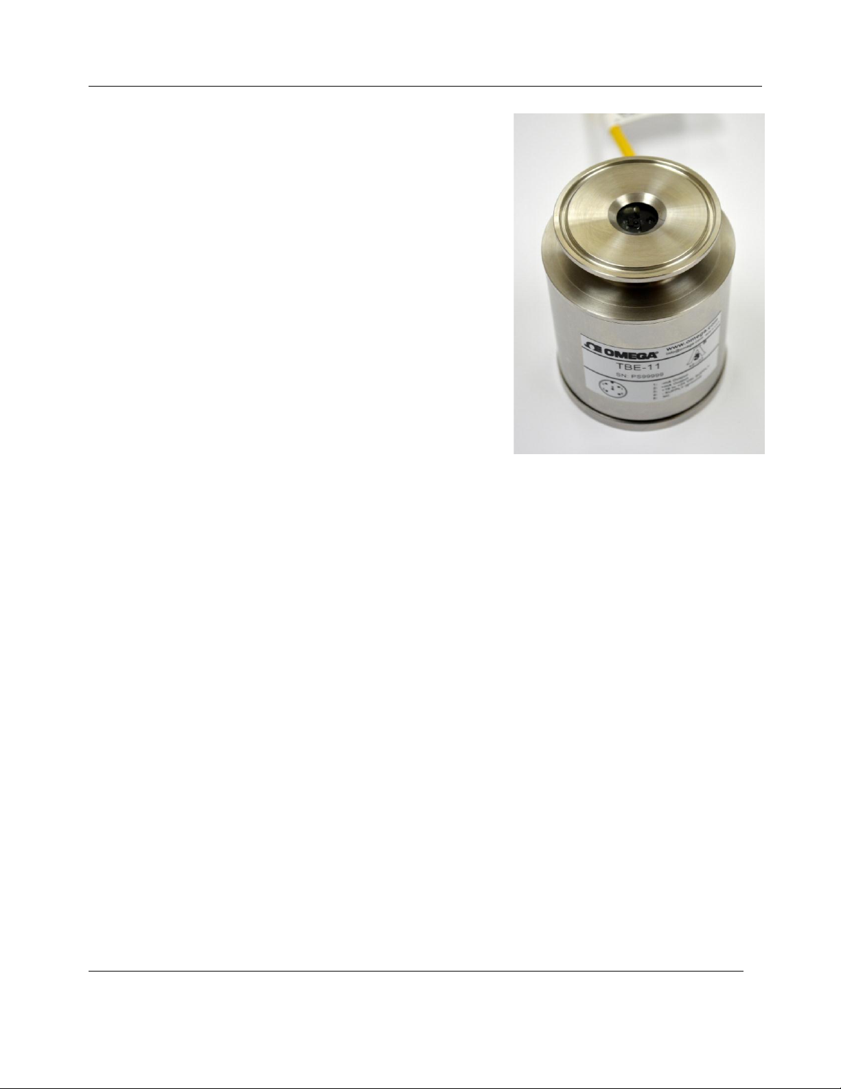
Figure 1: TBE-10 Turbidity Transmitter
Product Description
TBE-10 is an in-line optical sensor that mounts directly to the
process line, providing real-time information about the process.
TBE-10 can accurately detect the point of transition from water
to product, which is the primary application. Depending on the
degree of solids difference between two materials, it can also
detect a product–to-product transition. And for products such
as skim, 1 percent, 2 percent and whole milk, TBE-10 can act as
a monitor of milk fat percentage and an indicator of product
quality.
The most common calibration entered into TBE-10 includes
points for water, skim milk, 1 percent milk, 2 percent milk,
whole milk and a maximum response standard equal to 20 mA.
The 3A authorized TBE-10 also has uses in the brewing,
pharmaceutical, and juice processing industries. The device
accurately monitors turbidity and product concentration and
can help processors recover as much product as possible before a cleaning cycle begins. It can also help
to ensure equipment adds costly chemicals at the appropriate time.
The TBE-10 sensor assists in determining if fluid should be added to recovery tanks or sent to the drain,
and is an excellent monitor of BOD loading on waste lines. Solid construction means the TBE-10 sensor
stands up to the high temperatures and temperature fluctuations.
Principle of Operation
Utilizing advanced optical technology, TBE-10 sends a beam of infrared light into the process and
measures the backscatter, which is proportional to solids concentration. The device’s internal
microprocessor then converts the scatter to a linearized 4-20 mA output, which easily links to a PLC, DCS
or data logger.
Features
3A Authorized to 46-03 standard
Real-time process control
Detects phase transitions
Stainless steel construction
Sapphire lens
Sanitary clamp connections
NEMA 6 /IP67 enclosure
Easy to install, set up and maintain
7
Page 8

Technical Specifications
Mechanical
Materials: 316-series stainless steel housing and fittings; sapphire and FDA-approved silicone
product contact surface
Dimensions: 3.0" diameter x 3.7" length (approx.)
Weight: 3 lbs. (approx.)
Ratings: NEMA 4X (water-tight, corrosion proof); authorized to carry 3-A symbol
(Standard 46-03)
Optical Lens: uncoated, optical sapphire (aluminum oxide) min. thickness = 2.3mm
Lens Seal: 60 durometer, FDA-approved silicone rubber (meets ZZR-765-E, Class 2 A&B)
Lens Surface Finish: 0.1 microns
Performance/Electrical
Accuracy: +/-0.2% of span at 4 mA (water)
Repeatability: +/-1.0% of span in any target fluid
Process Temp Range: 32° to 250°F (continuous)
Ambient Temp Range: 40° to 120°F
Process Temp Shock: withstands instantaneous changes of up to 125°F (e.g. From 40° to
165°F during CIP, or from 125° to 250°F during SIP)
Temperature Effect: 0.9% of span/10°F change (process and/or ambient) maximum
Process Temperature Limits: vacuum to 200 psig at rated temperature
Output: 4-20 mA, 3 or 4 wire
Power: 18-24 VDC, at 35 mA
Connection: M12 5-pin, water-tight, with quick-disconnect cabling
Preliminaries
Standard Shipments
Unless specified otherwise, TBE-10 sensors are shipped with a standard calibration covering a span of
4-20 mA and representing clean water at 4 mA and a maximum white standard at 20 mA. A calibration
document is included in the shipment to inform you of the calibration date and details.
Unpack and Check Contents
Upon receipt of the shipment, carefully remove all items from the shipping package and compare the
contents to the shipping documents.
8
Page 9

Notice
Also check:
The TBE-10 sensor and other components for any damage that may have occurred during
shipping.
To make sure the sapphire lens is clean and undamaged. (If the lens needs to be cleaned, clean
it gently with a mild soap solution and a soft, clean cloth.)
The sensor’s electrical connector; it should easily mate with the connector pins on the sensor
body.
To make sure the threaded collar allows a snug, secure fit when fully engaged.
Electrical Connections
TBE-10 has a 5-pin electrical connector. If you purchased the molded, NEMA-6 electrical connector and
cable from Omega, simply connect the cable as provided.
If you are using the Hirschmann connector (Part Number 932 878-100 ELST 512 PG9 (www.hirschmann-
usa.com) and need to make a cable connection, please read the following steps.
The most common wiring scheme for TBE-10 is a 3-wire connection:
Pin 2 is the mA output
Pin 3 is the 18 to 24 VDC power supply
Pin 4 is the ground (negative side of the supply).
A 4-wire connection can also be used to connect TBE-10. In this wiring scheme, connect
Pin 1 (the negative side of the mA output)
Pin 2 (positive side of the mA output)
Pin 3 (18 to 24 VDC power supply)
Pin 4 (ground).
Pin 1 is the negative side of the mA output and is connected internally to Pin 4. This makes it more
convenient if you want to make a 4-wire connection.
Pin 5, located in the center of the connector is not used.
Once you make the connections inside the electrical connector, tighten the threaded cord grip on the
connector. This helps keep moisture from entering.
9
Page 10

Notice
Notice
Operation
Once TBE-10 is calibrated and you make the proper electrical connections, the sensor is ready for
operation. Before attaching the sensor to the process line, however, it is advisable to perform a quick
check of the unit’s operation.
You must connect the sensor output to a digital display, multimeter or some other electronics that allows
you to monitor the TBE-10’s mA output.
Applying Power
To view the unit’s internal electronics board, remove the screw lid on the housing (see Figure 3, page
16). When you apply power to the TBE-10 sensor, the green LED on the unit’s internal electronics board
blinks.
When the sensor is operating within the current calibration range, the Green LED on the sensor’s
electronics board blinks alone. When over-range, the Red and Green LEDs blink, and when below range,
the Green and Yellow LEDs blink.
Test Output
1. Place a white paper towel on a table.
2. With the lens facing down, place the sensor on the towel. This should produce an output of
approximately 17 mA. The actual output may range from 16 to 19 mA; this is normal.
3. Lift the sensor straight up, approximately 2 inches above the towel. This should yield a signal of
4 to 4.5 mA.
4. Slowly lower the sensor back to the towel; the mA output will increase as the sensor gets closer
to the towel, eventually reaching approximately 17 mA.
If the sensor performs as stated in the previous test, it is ready for installation. If not, call Omega for
technical assistance.
The TBE-10 is designed to meet CIP requirements. When cleaning the TBE-10, make sure to follow the
same requirements as the installation piping.
Installation
TBE-10 has a conventional sanitary clamp connector that attaches directly to a tee or saddle in the
process line or vessel. TBE-10 comes in standard 1.5, 2, 2.5 and 3 inch sizes.
10
Page 11

Caution
You can install TBE-10 in a wide variety of configurations, including vertical and horizontal process lines
and tanks. To optimize the performance of the sensor, it is important to:
keep the deadleg as short as possible on the tee connection, and
choose an installation site that minimizes air or sediment from collecting on the sensor’s lens.
Deadleg
To minimize deadleg, cut the tee back so the TBE-10 lens is as close as possible to the process stream. In
most cases, it is possible to cut the tee back and have a resulting deadleg of 1 to 2 inches. The shorter
the deadleg the better.
Installation Site
Select an installation site and orientation that minimizes the possibility of air or sediment interfering
with the sensor’s readings.
Vertical
Vertical sections of process lines are excellent installation sites, whether the flow is down or up.
Horizontal
Another excellent installation site is a 90-degree elbow on a horizontal line. In this case, position the
TBE-10 device so the fluid flows directly at the sensor’s lens.
Straight Sections
If installed on a straight section of horizontal process line, place TBE-10 so it looks sideways into the
process stream, not up or down.
Installations Not Recommended
Two installations not recommended are:
on the top of horizontal process lines, where air has a tendency to accumulate, and
on the bottom of horizontal process lines, where sediment can accumulate.
Clamp Connection Gasket
The clamp connection requires a gasket between TBE-10 and the tee. In most cases, the customer
provides the gasket and the tee. Customers can purchase these products from Omega if necessary.
Connect
Connect the sensor to the process pipe with the appropriate sanitary gasket and clamp. Orient the
sensor so that the electrical connector points toward the floor (see Figure 2, page 15).
The sapphire lens can be damaged if struck by sharp or hard objects or if the sensor is dropped during
installation. Take care when connecting the sensor to the tee so the lens isn't damaged.
11
Page 12

Caution
Notice
Notice
Caution
Calibration Verification or Test with Your Samples
The factory normally calibrates TBE-10 according to customer specifications and in most cases, the
factory calibration is sufficient for the application. However, if you want to verify the calibration or
determine the sensor’s response on your samples follow the steps below and record the response.
A common setup is to close off the bottom leg of the tee with an end cap, attach TBE-10 to the middle
leg, and pour the sample in the top leg. (see Figure 2 page 15)
1. Obtain samples of all products that this system will process. You will need enough of each to fill
the internal volume of the test setup.
2. Connect TBE-10 to the required power supply. Attach the sensor to a suitable test stand.
3. Be sure to wire the TBE-10 device properly to either the receiver or to a Multi-meter so you can
view the corresponding signal output from the unit. When you supply power to the TBE-10, the
green LED on the electronics board blinks.
Be careful not to dilute or otherwise contaminate the samples between readings. Also, if the highest
degree of accuracy is desired, make sure the samples are at the same temperature as they will be in the
process line.
4. Starting with the product containing the least amount of solids (lowest turbidity), completely fill
the test volume.
Before taking any readings, make sure to cover the opening of the test cylinder to make sure no external
light can enter the liquid. Any external infrared light could affect readings.
5. Record the output for this product, then move to the next, ending with the product containing
the greatest amount of solids.
When the sensor is operating within the current calibration range, the Green LED on the sensor’s
electronics board blinks alone. When over-range, the Red and Green LEDs blink, and when below range,
the Green and Yellow LEDs blink.
The resulting profile corresponds to the outputs from the unit at each of the various products. Use these
values as the reference for programming a receiver or to verify calibration of the TBE-10 sensor.
Changes in product properties (solids content) are a common cause for discrepancy. If observed, follow
the Calibration Procedure below.
12
Page 13

Notice
Caution
Calibration Procedure
If you want to adjust the calibration, follow this procedure:
1. Obtain samples of all products that will be processed in this system. If using liquid sample, you
need sufficient volume of each to fill the tee. Calibrate them in increasing order of
concentration. TBE-10 allows you to choose a variety of calibrations, from a 2-point calibration
to a 9-point calibration.
2. Be sure you wire the unit to either the receiver or to a Multi-meter so you are able to view the
corresponding signal output from the unit.
3. Remove the screw lid on the housing by turning it counterclockwise. This allows access to the
electronics board. Refer to Figure 3 on page 16 to locate the Calibration Switch, Entry Key and
Offset Adjustment Keys.
Be careful not to damage the cover o-ring. If damaged, it must be replaced.
4. As shown in Figure 2 on page 15, fill the tee with clean water, or another fluid that you desire to
be the 4 mA reference (if a value other than 4 mA is desired for the base value, please see
SENSOR OFFSET and SPAN CALIBRATION section below).
5. Observe the mA reading that TBE-10 produces with the 4 mA reference sample. If the output is
4 mA, there is no need to adjust. If you desire to change the zero point, turn the calibration
switch to position “0”. Press the UP or DOWN buttons until the desired mA offset reading is
reached. Then press and hold the ENTRY key for approximately two seconds. This stores the
new value as 4mA.
6. Remove the water or optional base product and fill the tee with the next highest solids content.
So as not to introduce error in calibration, it is critical to rinse the tee with water to clean any residue of
the previous product from the face of the sensor and calibration tee.
7. Turn the CALIBRATION SWITCH to position 1. Press and hold the ENTRY key for approximately
two seconds. The sensor output is now set to 20 mA (or the span setting).
8. Repeat step 7, incrementing the CALIBRATION SWITCH by one, until you have calibrated all
points (maximum is to switch position 8). As you add points, each addition becomes the new 20
mA top end. Each previously entered point is linearly re-scaled.
9. In general, a five (5) point calibration is sufficient to provide proper output resolution. You may
use calibration point 0 to 8. Point 9 is reserved for the Sensor Span Output adjustment,
described below.
10. To obtain output values, place the sensor again into each of the test liquids. With each product,
record the resulting current output from the transmitter. The resulting profile corresponds to
the outputs from the unit at each of the various products.
11. These values can now be used to program a receiver.
13
Page 14

Caution
Caution
Caution
Notice
For correct signal output scaling, make sure to leave the switch setting at the last calibration point
during operation.
Sensor Offset and Span Calibration
The TBE-10 sensor is typically scaled at the factory with 4 mA output for the “base reference” material
(first calibration point) and 20 mA for the material with highest turbidity value (last calibration point).
For most applications, it is recommended that the unit be used in this configuration. The following
procedure illustrates steps to verify or modify these values.
1. Remove the screw lid on housing.
Be careful not to damage rubber o-ring. If o-ring is damaged it must be replaced.
1. Refer to the Figure 3 on page 16 to locate the Calibration Switch, Entry Key and Offset
Adjustment Keys.
2. If you wish to change the span value, place the Calibration switch in Position “9” and press the
“UP” or “DOWN” offset adjustment keys until you obtain the desired value; then press and hold
the ENRTY key for approximately 2 seconds to store value.
3. If you wish to change the “base reference” value, place the Calibration switch in Position “0” and
press the “UP” or “DOWN” keys until you obtain the desired value; then press and hold the
ENTRY key for approximately 2 seconds.
Be sure to set the switch back to the position used for the last calibration value or the output scaling will
be incorrect
Clean Sweep
Clean Sweep is a feature which resets the sensors programmed values back to factory defaults. This is
usually used in cases where someone wants to completely recalibrate a unit. To Clean Sweep a unit,
with the unit powered up, press and hold the UP, DOWN & ENTRY keys at the same time for about 3-5
seconds. Once the buttons are pushed, the Green LED will turn off and then back on solid, after which
the Red LED will start to blink. Once the Red LED blinks, release the keys. When Clean Sweep has been
completed the Green LED will flash. The Red LED may also blink which is ok.
Once Clean Sweep has been performed, there is no way to get the previous values back.
14
Page 15
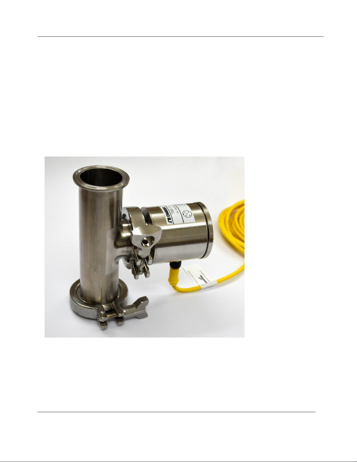
Figure 2: TBE-10 Sensor attached to a sanitary T, electrical connection facing floor
Figure 4 on page 17 shows an example of a multi-point calibration. For this example, milk samples were
used. Water = 4 mA, skim milk = 8 mA, 1% milk = 12 mA, 2% milk = 16 mA and whole milk = 20 mA. The
calibration selector switch was at 0 position for water, 1 position for skim milk, 2 position for 1% milk, 3
position for 2% milk and 4 position for whole milk.
Figure 5 on page 18 shows a slightly different example of a multi-point calibration. In this case, a dairy
customer wanted a greater degree of sensitivity near 1% milk fat; a 6-point calibration was used, which
emphasized the 1% to 1.3% milk fat concentration. All that was necessary was to prepare samples of the
proper concentration. The TBE-10 calibration linearizer divided the 4-20 mA span into five sections of
3.2 mA each, including the key range in the middle of the graph.
If questions arise at any time, please contact Omega.
15
Page 16
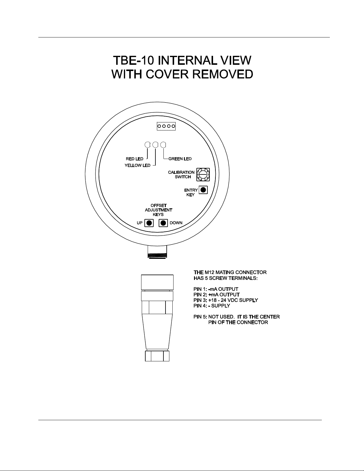
Figure 3: TBE-10 with cover removed showing LEDs, connector, calibration switch, entry key, adjustment keys, etc.
16
Page 17
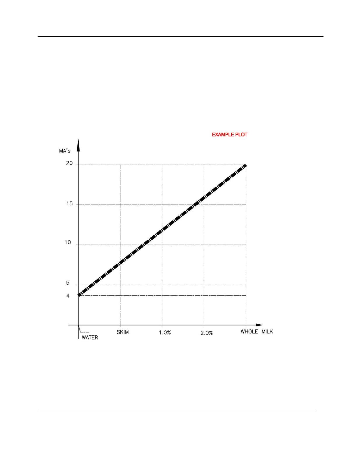
Figure 4: Calibration linearizer, 4 point
17
Page 18
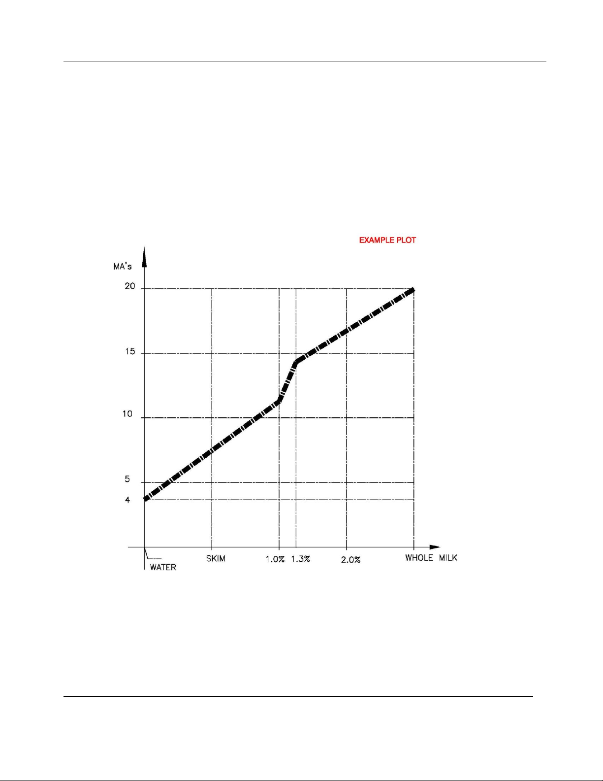
Figure 5: Calibration lineariser, 5 point
Figure 5: Recalibration
18
Page 19

MATERIAL USED TO CALIBRATE _______________________________
DATE _______________________
CALIBRATED BY: ___________________________________________
CALIBRATION POINT 1: ___________________________________ mA
CALIBRATION POINT 2: ___________________________________ mA
CALIBRATION POINT 3: ___________________________________ mA
CALIBRATION POINT 4: ___________________________________ mA
CALIBRATION POINT 5: ___________________________________ mA
CALIBRATION POINT 6: ___________________________________ mA
CALIBRATION POINT 7: ___________________________________ mA
CALIBRATION POINT 8: ___________________________________ mA
BASE LINE _____________________________________________ mA
Figure 6: Factory calibration information
19
Page 20
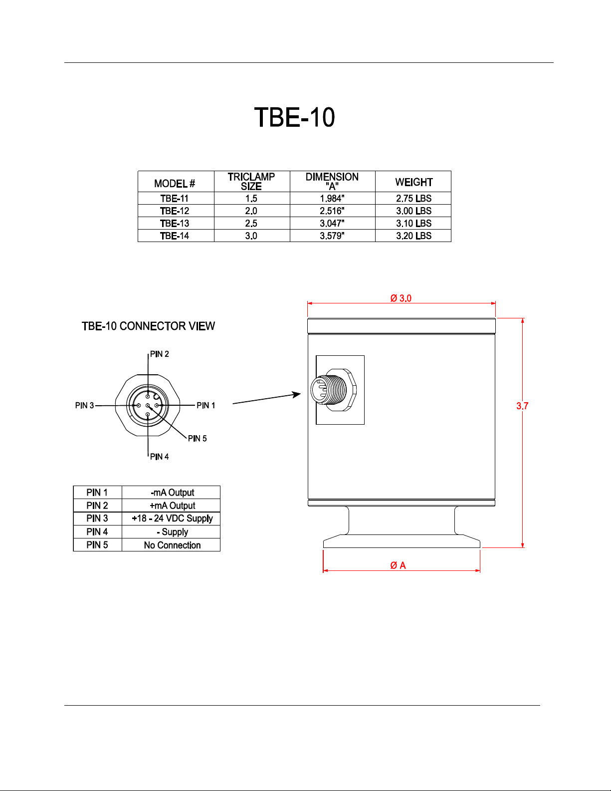
Figure 7: Dimensions, weights and connector diagram
20
Page 21

21
Page 22

22
Page 23

WARRANTY/DISCLAIMER
OMEGA ENGINEERING, INC. warrants this unit to be free of defects in materials and workmanship for a
period of 13 months from date of purchase. OMEGA’s WARRANTY adds an additional one (1) month
grace period to the normal one (1) year product warranty to cover handling and shipping time. This
ensures that OMEGA’s customers receive maximum coverage on each product.
If the unit malfunctions, it must be returned to the factory for evaluation. OMEGA’s Customer Service
Department will issue an Authorized Return (AR) number immediately upon phone or written request.
Upon examination by OMEGA, if the unit is found to be defective, it will be repaired or replaced at no
charge. OMEGA’s WARRANTY does not apply to defects resulting from any action of the purchaser,
including but not limited to mishandling, improper interfacing, operation outside of design limits,
improper repair, or unauthorized modification. This WARRANTY is VOID if the unit shows evidence of
having been tampered with or shows evidence of having been damaged as a result of excessive corrosion;
or current, heat, moisture or vibration; improper specification; misapplication; misuse or other operating
conditions outside of OMEGA’s control. Components in which wear is not warranted, include but are not
limited to contact points, fuses, and triacs.
OMEGA is pleased to offer suggestions on the use of its various products. However,
OMEGA neither assumes responsibility for any omissions or errors nor assumes liability for any
damages that result from the use of its products in accordance with information provided by
OMEGA, either verbal or written. OMEGA warrants only that the parts manufactured by the
company will be as specified and free of defects. OMEGA MAKES NO OTHER WARRANTIES OR
REPRESENTATIONS OF ANY KIND WHATSOEVER, EXPRESSED OR IMPLIED, EXCEPT THAT OF
TITLE, AND ALL IMPLIED WARRANTIES INCLUDING ANY WARRANTY OF MERCHANTABILITY
AND FITNESS FOR A PARTICULAR PURPOSE ARE HEREBY DISCLAIMED. LIMITATION OF
LIABILITY: The remedies of purchaser set forth herein are exclusive, and the total liability of
OMEGA with respect
indemnification, strict liability or otherwise, shall not exceed the purchase price of the
co mpone nt upon which liab ility is based. In no event shall OMEGA be liabl e for
consequential, incidental or special damages.
CONDITIONS: Equipment sold by OMEGA is not intended to be used, nor shall it be used: (1) as a “Basic
Component” under 10 CFR 21 (NRC), used in or with any nuclear installation or activity; or (2) in medical
applications or used on humans. Should any Product(s) be used in or with any nuclear installation or
activity, medical application, used on humans, or misused in any way, OMEGA assumes no responsibility
as set forth in our basic WARRANTY/DISCLAIMER language, and, additionally, purchaser will indemnify
OMEGA and hold OMEGA harmless from any liability or damage whatsoever arising out of the use of the
Product(s) in such a manner.
his order, whether based on contract, warranty, negligence,
to t
RETURN REQUESTS/INQUIRIES
Direct all warranty and repair requests/inquiries to the OMEGA Customer Service Department. BEFORE
RETURNING ANY PRODUCT(S) TO OMEGA, PURCHASER MUST OBTAIN AN AUTHORIZED RETURN
(AR) NUMBER FROM OME G A’ S CU S T O M ER SE RVI C E D E PA RT M E N T ( I N O R D ER T O AV OID
PROCESSING DELAYS). The assigned AR number should then be marked on the outside of the return
package and on any correspondence.
The purchaser is responsible for shipping charges, freight, insurance and proper packaging to prevent
breakage in transit.
FOR WARRANTY
following information available BEFORE
contacting OMEGA:
1. Purchase Order number under which the product
was PURCHASED,
2. Model and serial number of the product under
warranty, and
3. Repair instructions and/or specific problems
relative to the product.
OMEGA’s policy is to make running changes, not model changes, whenever an improvement is possible. This affords
our customers the latest in technology and engineering.
OMEGA is a registered trademark of OMEGA ENGINEERING, INC.
© Copyright 2009 OMEGA ENGINEERING, INC. All rights reserved. This document may not be copied, photocopied,
reproduced, translated, or reduced to any electronic medium or machine-readable form, in whole or in part, without the
prior written consent of OMEGA ENGINEERING, INC.
RETURNS, please have the
FOR NON-WARRANTY REPAIRS,
for current repair charges. Have the following
information available BEFORE contacting OMEGA:
1. Purchase Order number to cover the COST
of the repair,
2. Model and serial number of the product, and
3. Repair instructions and/or specific problems
relative to the product.
consult OMEGA
Page 24

Where Do I Find Everything I Need for
Process Measurement and Control?
OMEGA…Of Course!
Shop online at omega.com
SM
TEMPERATURE
Thermocouple, RTD & Thermistor Probes, Connectors, Panels & Assemblies
Wire: Thermocouple, RTD & Thermistor
Calibrators & Ice Point References
Recorders, Controllers & Process Monitors
Infrared Pyrometers
PRESSURE, STRAIN AND FORCE
Transducers & Strain Gages
Load Cells & Pressure Gages
Displacement Transducers
Instrumentation & Accessories
FLOW/LEVEL
Rotameters, Gas Mass Flowmeters & Flow Computers
Air Velocity Indicators
Turbine/Paddlewheel Systems
Totalizers & Batch Controllers
pH/CONDUCTIVITY
pH Electrodes, Testers & Accessories
Benchtop/Laboratory Meters
Controllers, Calibrators, Simulators & Pumps
Industrial pH & Conductivity Equipment
DATA ACQUISITION
Data Acquisition & Engineering Software
Communications-Based Acquisition Systems
Plug-in Cards for Apple, IBM & Compatibles
Datalogging Systems
Recorders, Printers & Plotters
HEATERS
Heating Cable
Cartridge & Strip Heaters
Immersion & Band Heaters
Flexible Heaters
Laboratory Heaters
ENVIRONMENTAL
MONITORING AND CONTROL
Metering & Control Instrumentation
Refractometers
Pumps & Tubing
Air, Soil & Water Monitors
Industrial Water & Wastewater Treatment
pH, Conductivity & Dissolved Oxygen Instruments
M-5375/1213
 Loading...