

Page 1
STCTX SERIES
NOTE
Industrial Thermocouple Connector/Transmitter
INSTRUCTION
SHEET
M3935A/1112
Shop online at: omega.com e-mail: [email protected]
For latest product manuals: omegamanual.info
General Description
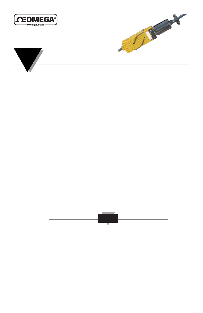
The OMEGA®STCTX Series is a medium performance, low cost, Industrial
TC (Thermocouple) Connector/Transmitter. The STCTX features an
encapsulated micro miniature signal conditioner built into a Universal
Thermocouple Connector that converts the microvolt signal from a
thermocouple sensor or probe across a dedicated temperature range to an
industry standard 2-wire, 4 to 20mA analog output. This analog output can
be sent hundreds of feet away from the location of your sensor (probe) to an
indicating device, controller, PLC, computer, data logger or chart recorder.
Your STCTX Connector/Transmitter has been factory calibrated to provide
maximum performance and should require no field adjustments when
received.
Note: Patents & Patents Pending
Unpacking
Remove the packing list and verify that you have received all of your
OMEGA equipment. If you have any questions about the shipment, please
call Customer Service at:
When you receive the shipment, inspect the container and equipment for
any signs of damage. Note any evidence of rough handling in transit.
Immediately report any damage to the shipping agent.
The carrier will not honor any damage claims unless all
shipping material is saved for inspection. After examining and
removing contents, save packing material and carton in the
event reshipment is necessary.
The following items are supplied in the box with your STCTX
Connector/Transmitter.
• This User's Manual, # M3935A (1 ea.)
• Probe/Connector Locking Clips (2 ea.)
Page 2

STCTX Series Industrial Thermocouple Connector/Transmitter
STCTX Series Thermocouple Connector/ Transmitter Models Available
Model No. Description Range
STCTX-J1 with Universal Connector -18 to 121°C (0 to 250°F)
STCTX-J2 with Universal Connector -18 to 538°C (0 to 1000°F)
STCTX-K1 with Universal Connector -18 to 121°C (0 to 250°F)
STCTX-K2 with Universal Connector -18 to 538°C (0 to 1000°F)
STCTX-K3 with Universal Connector -18 to 1093°C (0 to 2000°F)
STCTX-T1 with Universal Connector -18 to 121°C (0 to 250°F)
STCTX-T2 with Universal Connector -18 to 399°C (0 to 750°F)
SPRTX Series RTD Connector/ Transmitter Models Available
Model No. Description Range
SPRTX-S1 with Standard Size Connector -99 to 208°C (-146 to 406°F)
SPRTX-S2 with Standard Size Connector 2 to 569°C (36 to 1056°F)
SPRTX-M1 with Miniature Size Connector -99 to 208°C (-146 to 406°F)
SPRTX-M2 with Miniature Size Connector 2 to 569°C (36 to 1056°F)
Recommended Accessories
Regulated Power Supply, OMEGA
Shielded 2-conductor cable (100 ft), OMEGA
®
Part No.: PSR-24L
®
Part No.: TX2-100
2
Page 3

STCTX Series Industrial Thermocouple Connector/Transmitter
NOTE
Introduction/Safety
Your STCTX Thermocouple Connector/Transmitter has been designed for
ease of use and flexibility. It is important that you read this User's Manual
completely and follow all safety precautions before operating your unit.
Precautions
1. FOLLOW ALL SAFETY PRECAUTIONS AND OPERATING
INSTRUCTIONS OUTLINED IN THIS MANUAL.
2. INSURE PROBE/CONNECTOR SAFETY CLIPS ARE ALWAYS
INSTALLED DURING USE.
3. ADD ADDITIONAL SAFE GUARDS TO YOUR SYSTEM IN
CRITICAL APPLICATIONS WHERE DAMAGE OR INJURY MAY
RESULT FROM PROBE/CONNECTOR SEPARATION OR FAILURE.
4. NEVER EXPOSE THE CONNECTOR/MODULE BODY TO
AMBIENT TEMPERATURES ABOVE 85ºC (185ºF) OR BELOW -40°C
(-40°F). DAMAGE MAY RESULT.
5. DO NOT OPERATE IN FLAMMABLE OR EXPLOSIVE
ENVIRONMENTS.
6. DO NOT USE IN HUMAN, MEDICAL, OR NUCLEAR
APPLICATIONS.
7. NEVER OPERATE WITH A POWER SOURCE OTHER THAN WHAT
IS SPECIFIED IN THIS MANUAL.
8. REMOVE AND/OR DISCONNECT POWER SOURCE BEFORE
ATTEMPTING INSTALLATION OR MAINTENANCE.
9. ALWAYS OPERATE YOUR UNIT WITH THE SHIELD WIRE
CONNECTED TO EARTH GROUND.
10. INSTALLATION AND WIRING SHOULD BE DONE BY TRAINED
PROFESSIONALS ONLY.
11. DO NOT OPEN OR DISASSEMBLE YOUR UNIT.
There are no user serviceable parts inside your unit. Attempting
to open, repair or service your unit will void your warranty.
3
Page 4
STCTX Series Industrial Thermocouple Connector/Transmitter
24V
500°C
PROCESS METER
OR CONTROLLER
1000 FT. MAX
+
+
–
–
THERMOCOUPLE
PROBE
STCTX
CONNECTOR/
TRANSMITTER
MANUFACTURING AREA CONTROL ROOM
DC POWER SUPPLY
Theory of Operation
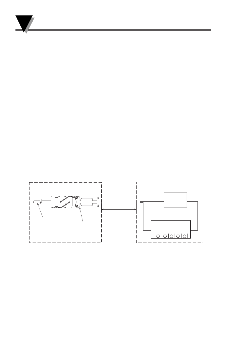
A 4 to 20 mA loop is a series loop in which a transmitter will vary the
current flow depending on the input to the transmitter. With the STCTX the
amount of current allowed to flow in the loop will vary depending on the
microvolt change, due to changes in the temperature being measured by the
thermocouple sensor (probe). Some advantages of a current output over a
voltage output is that the signal measured is less susceptible to electrical
noise interference and the loop can support more than one measuring
instrument as long as the maximum loop resistance is not exceeded.
A typical application utilizing a current loop will normally consist of a
power supply, the transmitter and a meter, recorder or controller to
measure the current flow. The loop resistance in the sum of the measuring
instruments and wire used. The maximum allowable loop resistance for the
STCTX to function properly is found by using the following formula:
Rmax = (power supply voltage – 9 volts)/ .02 amps
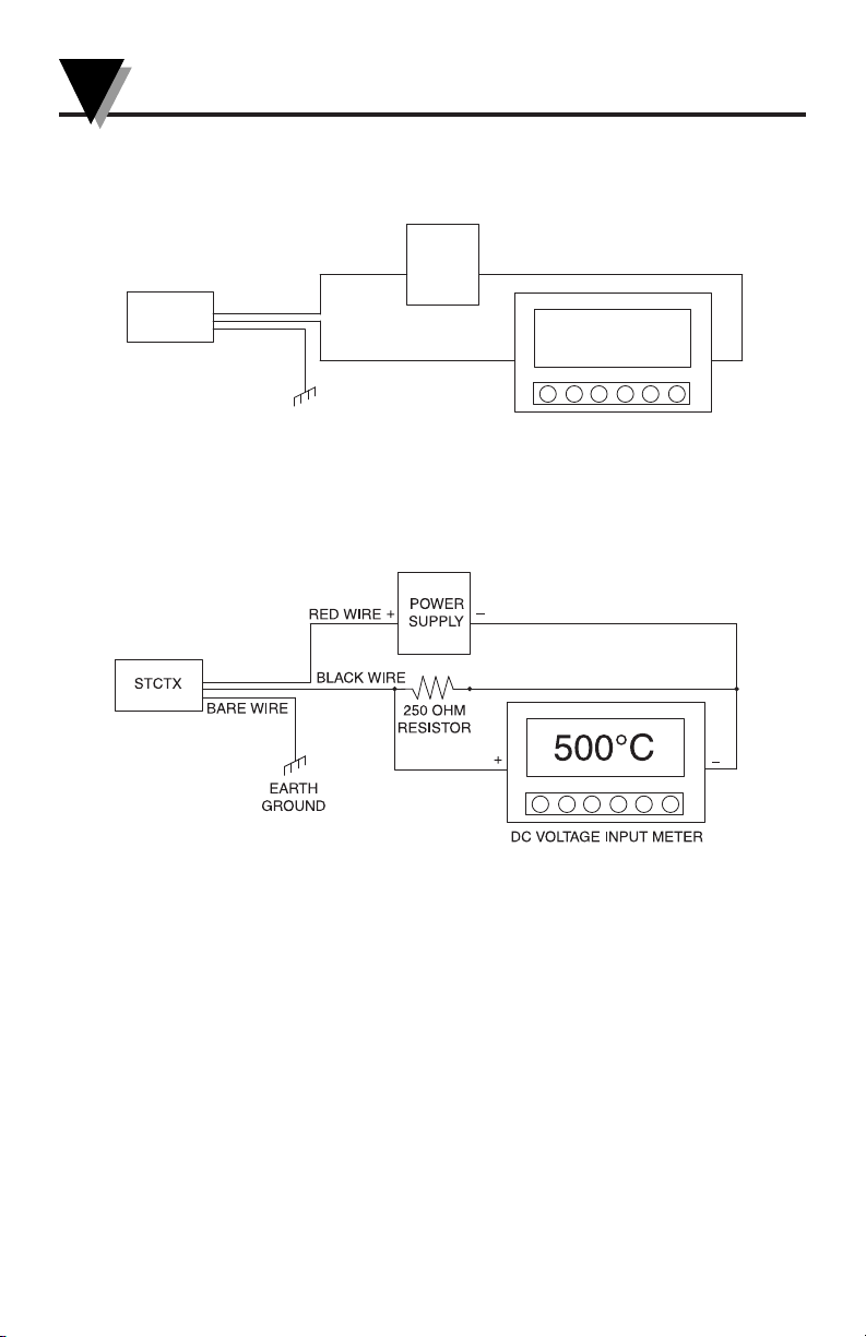
For applications that require a voltage output, the 4 to 20mA signal from the
STCTX can be converted in the field by adding a 250 Ohm shunt resistor
that will convert the transmitters output to a 1 to 5 Vdc signal when wired
correctly. See “Transmitter Wiring Examples” in this manual.
4
Page 5
STCTX Series Industrial Thermocouple Connector/Transmitter
CAUTION
LOCKING CLIPS INSTALLED
Mounting Your STCTX to Probes
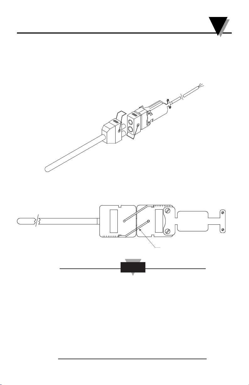
The STCTX Series Connector/Transmitters are designed for quick
connection to Thermocouple sensors and probes. The STCTX will connect to
all industry Thermocouple probes that feature “Omega Style” standard or
miniature male connectors such as Omega OST-K-M standard size
connector or SMP-K-M miniature size connector.
See below for correct usage.
Probe Locking Clips
Probe locking clips are also provided to help secure your probe to the
STCTX Connector/Transmitter.
Although your STCTX Connector/Transmitter will work with any
Thermocouple sensor or probe, It is recommended that you use
only OMEGA
®
Thermocouple probes with you STCTX unit to
insure proper installation and use of the probe locking clips.
Probe locking clips are provided to offer added protection
against the separation of your probe and connector/transmitter.
In critical applications where separation of the Thermocouple
probe from the connector/transmitter during normal operation
could cause damage or harm, it is recommended that you install
additional safety and locking devices to prevent the units from
separating and/or shutting down your process.
5
Page 6
STCTX Series Industrial Thermocouple Connector/Transmitter
BARE WIRE
EARTH
GROUND
STCTX
RED WIRE
POWER
SUPPLY
+
+
–
–
BLACK WIRE
DC VOLTAGE INPUT METER
500°C
Transmitter Wiring Examples
4 to 20mA Output (2-wire)
Converting from 4 to 20mA Output to 1 to 5Vdc Output (3-wire)
6
Page 7
STCTX Series Industrial Thermocouple Connector/Transmitter
HIGH
TEMPERATURE
INSULLATION
COMPRESSION
FITTING
3"
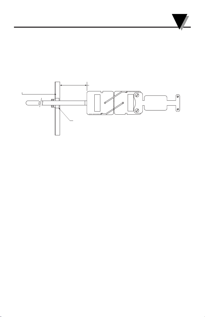
Protection from High Ambient Temperatures
Note: Your STCTX Connector/Transmitter Assembly can be damaged if
exposed to ambient temperatures above 85ºC (185ºF). Some applications may
require that you shield the STCTX unit from radiated heat as shown below.
You should always use a probe where the length allows for a safe distance of
76 mm (3") or more between the body of the STCTX and your source of heat.
7
Page 8
STCTX Series Industrial Thermocouple Connector/Transmitter
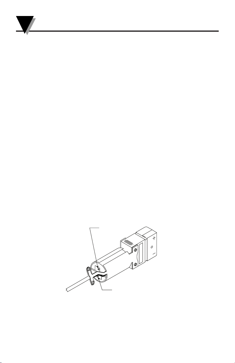
SPAN
(P2)
ZERO (P1)
Calibration/Service
Your transmitter has been factory calibrated to meet or exceed the
specifications outlined in this manual. No field adjustments should be
needed. If your unit should become damaged or malfunction, please contact
Omega Customer Service at:
Calibration Procedure
Equipment Required:
1. Regulated DC Power Supply, 12-24 Vdc @ 30 mA
2. Digital DC Current Meter
3. Thermometer Simulator (Omega Model CL23A)
4. Test Leads
1. Connect the power supply, milli-amp meter and Thermometer simulator as
shown on page 5 of this manual.
2. Set the Thermocouple simulator to the correct calibration type for the units
being tested.
3. Set the Thermocouple simulator for the low end setting for the thermometer
type you are testing.
4. Adjust "P1" on the STCTX for 4.00 mA output.
5. Set the Thermocouple simulator for the high end setting for the thermocouple
type you are testing.
6. Adjust "P2" on the STCTX for 20.00 mA output.
7. Repeat steps 3, 4, 5, & 6 until correct readings are achieved.
8. Calibration complete.
Specifications
Temperature Input Range by model
STCTX-J1, -K1, -T1 -18 to 121ºC (0 to 250ºF)
STCTX-J2, K2 -18 to 538ºC (0 to 1000ºF)
STCTX-T2 -18 to 399ºC (0 to 750ºF)
STCTX-K3 -18 to 1093ºC (0 to 2000ºF)
8
Page 9
STCTX Series Industrial Thermocouple Connector/Transmitter
NOTE
NOTE
Accuracy: ±0.5% of full scale @ 23ºC
Thermocouple signals are non-linear. Your STCTX provides
amplification, not linearization. You must take into account the
non-linearity and inaccuracy of your thermocouple sensor to
calculate your combined system accuracy.
Repeatability: ±0.25ºC (0.5ºF)
Output Stability/ Temp Drift: ±0.015 mA/ºC
Max Ambient Temperature: -40 to 85 ºC (-40 to 185ºF)
Output: 2-Wire, 4 to 20mA
Power Supply: Regulated 9 to 24 Vdc @ 30mA max
Max Loop Resistance: Ohms = (V supply – 9 V)/.02 A
Sensor Input Type: Ungrounded Thermocouple (J, K, T)
Open Sensor Indication: Output goes above 20mA
Connector Style/ Material:
Universal Omega Model UST (Glass Filled Nylon)
Dimensions 79 x 18 x 24 mm (3.12 L x 0.70 W x .96"
Weight 100 g (0.22 lb)
Response Time: 120ms (0-63% of full scale)
• Cable shield wire must be connected to earth ground for
“Open Sensor Indication” to function correctly.
• The STCTX Series is not designed for use in medical or
nuclear applications, nor flammable or explosive
environments.
• The published performance tolerance of this product may be
derated by up to several percent if operated in the presence
of strong radio frequency energy. This condition may occur
if operation takes place within 1 or 2 Km of a commercial
radio or TV station or when communication devices, such as
walkie talkies, with signal strengths in the order of 1 watt or
greater are used in the area of operation.
• Patents and Patents Pending
9
Page 10

OMEGAnet®Online Service Internet e-mail
omega.com [email protected]
U.S.A.: Omega Engineering, Inc., One Omega Drive,
ISO 9001 Certified
Canada: 976 Bergar, Laval (Quebec), H7L 5A1, Canada
For immediate technical or application assistance:
U.S.A. and Sales Service: 1-800-826-6342/1-800-TC-OMEGA
Canada: Customer Service: 1-800-622-2378/1-800-622-BEST
China: 1698 Yi Shan Road, Unit 102, Min Hang District
It is the policy of OMEGA Engineering, Inc. to comply with all worldwide safety and EMC/EMI regulations that apply. OMEGA is constantly pursuing
certification of its products to the European New Approach Directives. OMEGA will add the CE mark to every appropriate device upon certification.
The information contained in this document is believed to be correct, but OMEGA accepts no liability for any errors it contains, and reserves the
right to alter specifications without notice.
WARNING: These products are not designed for use in, and should not be used for, human applications.
Servicing North America:
P.O. Box 4047, Stamford, CT 06907-0047 USA
Toll-Free: 1-800-826-6342 Tel: (203) 359-1660
FAX: (203) 359-7700 e-mail: [email protected]
®
Engineering Service: 1-800-872-9436/1-800-USA-WHEN
®
Serving Asia:
Shanghai, China 201103 P.R.C.
Hotline: 800 819 0559/400 619 0559
e-mail: [email protected]
Benelux: Toll-Free: 0800 099 3344 TEL: +31 20 347 21 21
Czech Frystatska 184
Republic: 733 01 Karviná, Czech Republic
France: Toll-Free: 0850 541 038 TEL: 01 57 32 48 17
Germany/ Daimlerstrasse 26
Austria D-75392 Deckenpfronn, Germany
®
United OMEGA Engineering Ltd.
Kingdom: One Omega Drive, River Bend Technology Centre,
ISO 9001
Certified
Servicing Europe:
FAX: +31 20 643 46 43 e-mail: [email protected]
TEL: +420-59-6311899 FAX: +420-59-6311114
e-mail: [email protected]
FAX: 01 57 32 48 17 e-mail: [email protected]
Toll-Free: 0800 8266342 TEL: +49 (0) 7056 9398-0
FAX: +49 (0) 7056 9398-29 e-mail: [email protected]
Northbank, Irlam,
Manchester M44 5BD, United Kingdom
Toll-Free: 0800-488-488 TEL: +44 (0) 161 777-6611
FAX: +44 (0) 161 777-6622 e-mail: [email protected]
OMEGA ENGINEERING, INC. warrants this unit to be free of defects in materials and workmanship for a period of 13 months from
WARRANTY/ DISCLAIMER
date of purchase. OMEGA’s WARRANTY adds a n additio nal one (1) month g race peri od to the n ormal one (1) year product
warrant y to cover handling and shipping time. This ens ures that OMEGA’s customers receive maximum coverage on each
product.
If the unit malfunctions, it must be returned to the factory for evaluation. OMEGA’s Customer Service Department will issue an
Authorized Return (AR) number immediately upon phone or written request. Upon examination by OMEGA, if the unit is found to be
defective, it will be repaired or replaced at no charge. OMEGA’s WARRANTY does not apply to defects resulting from any action of the
purchaser, including but not limited to mishandling, improper interfacing, operation outside of design limits, improper repair, or
unauthorized modification. This WARRANTY is VOID if the unit shows evidence of having been tampered with or shows evidence of
havi ng been damag ed as a re sult of exces sive corros ion; or curre nt, heat, moist ure or v ibrat ion; impro per specifi catio n;
misapplication; misuse or other operating conditions outside of OMEGA ’s control. Components in which wear is not warranted,
include but are not limited to contact points, fuses, and triacs.
OMEGA is pleased to offer suggestions on the use of its various products. However, OMEGA neither assumes responsibility
for any omissions or errors nor assumes liability for any damages that result from the use of its products in accordance with
information provided by OMEGA, either verbal or written. OMEGA warrants only that the parts manufactured by the
company will be as specified and free of defects. OMEGA MAKES NO OTHER WARRANTIES OR REPRESENTATIONS OF ANY
KIND WHATSOEVER, EXPRESSED OR IMPLIED, EXCEPT THAT OF TITLE, AND ALL IMPLIED WARRANTIES INCLUDING ANY
WARRANTY OF MERCHANTABILITY AND FITNESS FOR A PARTICULAR PURPOSE ARE HEREBY DISCLAIMED. LIMITATION
OF LIABILITY: The remedies of purchaser set forth herein are exclusive, and the total liability of OMEGA with respect to this
order, whether based on contract, warranty, negligence, indemnification, strict liability or otherwise, shall not exceed the
purchase price of the component upon which liability is based. In no event shall OMEGA be liable for consequential,
incidental or special damages.
CONDITIONS: Equipment sold by OMEGA is not intended to be used, nor shall it be used: (1) as a “Basic Component” under 10 CFR
21 (NRC), used in or with any nuclear installation or activity; or (2) in medical applications or used on humans. Should any Product(s)
be used in or with any nuclear installation or activity, medical application, used on humans, or misused in any way, OMEGA assumes
no responsibility as set forth in our basic WARRANTY/ DISCLAIMER language, and, additionally, purchaser will indemnify OMEGA and
hold OMEGA harmless from any liability or damage whatsoever arising out of the use of the Product(s) in such a manner.
Direc t all warranty an d r epair reques ts/inqu iries to the O MEGA Custome r S ervice De partme nt. BEFORE RETURNI NG ANY
PRODUCT(S) TO OMEGA, PURCHASER MUST OBTAIN AN AUTHORIZED RETURN (AR) NUMBER FROM OMEGA’S CUSTOMER
SERVICE DEPARTMENT (IN ORDER TO AVOID PROCESSING DELAYS). The assigned AR number should then be marked on the
outside of the return package and on any correspondence.
The purchaser is responsible for shipping charges, freight, insurance and proper packaging to prevent breakage in transit.
FOR WARRANTY
information available BEFORE contacting OMEGA:
1. Purchase Order number under which the product was
PURCHASED,
2. Model and serial number of the product under warranty, and
3. Repair instructions and/or specific problems relative to the
product.
OMEGA’s policy is to make running changes, not model changes, whenever an improvement is possible. This affords our customers the latest in
technology and engineering.
OMEGA is a registered trademark of OMEGA ENGINEERING, INC.
© Copyright 2012 OMEGA ENGINEERING, INC. All rights reserved. This document may not be copied, photocopied, reproduced, translated, or
reduced to any electronic medium or machine-readable form, in whole or in part, without the prior written consent of OMEGA ENGINEERING, INC.
RETURNS, please have the following
RETURN REQUESTS/INQUIRIES
FOR NON-WARRANTY REPAIRS,
current repair charges. Have the following information
available BEFORE contacting OMEGA:
1. Purchase Order number to cover the COST of the repair,
2. Model and serial number of the product, and
3. Repair instructions and/or specific problems relative to
the product.
consult OMEGA for
 Loading...