

Page 1

Page 2

06EN003490 Rev. E ST80/ST80L Flow Meter
Notice of Proprietary Rights
This document contains confidential technical data, including trade secrets and proprietary information which is the property of Fluid Components
International LLC (FCI).Disclosure of this data to you is expressly conditioned upon your assent that its use is limited to use within your company
only (and does not include manufacture or processing uses). Any other use is strictly prohibited without the prior written consent of FCI.
© Copyright 2021 by Fluid Compone nts Inte rnational LLC. All right s re served. FCI i s a registered trade mark of F luid Components Internat ional LLC. Infor mation subject to change w ithout not ice.
Fluid Components International LLC
Page 3

ST80/ST80L Flow Meter 06EN003490 Rev. E
Table of Contents
Table of Contents ......................................................................................................................................................................................iii
List of Figures ........................................................................................................................................................................................... v
List of Tables ............................................................................................................................................................................................vii
Typographical Conventions .................................................................................................................................................................... viii
1 GENERAL ......................................................................................................................................................................................... 1
Product Description ........................................................................................................................................................................... 1
Theory of Operation .......................................................................................................................................................................... 1
Safety Instructions ............................................................................................................................................................................. 1
Order Verification .............................................................................................................................................................................. 1
Technical Specifications .................................................................................................................................................................... 3
2 INSTALLATION ................................................................................................................................................................................. 7
Instrument Identification and Outline Dimensions ............................................................................................................................. 7
ST80 Insertion Sensor Installation .................................................................................................................................................... 7
ST80L In-Line Process Connection ................................................................................................................................................ 14
Installation of Probe with Moisture/Rain Shield ............................................................................................................................... 14
Flow Transmitter Electronics Installation ......................................................................................................................................... 16
Instrument Wiring ............................................................................................................................................................................ 20
Post Installation Check .................................................................................................................................................................... 29
3 OPERATION ................................................................................................................................................................................... 31
Basic Commissioning and Start-Up ................................................................................................................................................ 31
Configuring the ST80/ST80L ........................................................................................................................................................... 31
Verify Engineering Units .................................................................................................................................................................. 35
System Faults, Alarms and Logging Indication ............................................................................................................................... 35
ST80/ST80L Configuration Software Application (User Password: 2772) ...................................................................................... 36
Real Time Clock .............................................................................................................................................................................. 37
Totalizer Setup ................................................................................................................................................................................ 38
Configuring for AST™ or Constant Power Measurement Methods ................................................................................................ 39
Flow Filtering ................................................................................................................................................................................... 40
NAMUR Setup ................................................................................................................................................................................. 41
Internal Delta-R Resistor (idR) Check ............................................................................................................................................. 43
Using Digital Outputs ...................................................................................................................................................................... 46
HART Operation .............................................................................................................................................................................. 47
HART Command List Reference ..................................................................................................................................................... 52
Modbus Operation ........................................................................................................................................................................... 70
4 MAINTENANCE .............................................................................................................................................................................. 77
Introduction ..................................................................................................................................................................................... 77
General Maintenance ...................................................................................................................................................................... 77
Power Fuse Replacement ............................................................................................................................................................... 78
Lithium Battery Replacement .......................................................................................................................................................... 79
Fluid Components International LLC iii
Page 4

06EN003490 Rev. E ST80/ST80L Flow Meter
5 TROUBLESHOOTING .................................................................................................................................................................... 81
Non-Maintenance Observations ...................................................................................................................................................... 81
General Function Check ................................................................................................................................................................. 82
Troubleshooting the Flow Element .................................................................................................................................................. 83
Verification of the Electronics .......................................................................................................................................................... 85
Constant Power Configuration Troubleshooting ............................................................................................................................. 87
Defective Parts ................................................................................................................................................................................ 89
Customer Service ............................................................................................................................................................................ 89
Reference: Error/Status Register Information ................................................................................................................................. 90
APPENDIX A DRAWINGS .................................................................................................................................................................. 93
APPENDIX B ADDITIONAL INFORMATION .................................................................................................................................... 125
Parameters Report from the ST80/ST80L Configuration Application (Sample) ............................................................................ 126
HMI Menu Outline ......................................................................................................................................................................... 131
ST80/ST80L Configuration Software Menu Outline (v3.2.0.x) ...................................................................................................... 132
Instructions: Installing Sun Shield on ST80/ST80L Integral Enclosure ......................................................................................... 133
Instructions: Installing Sun Shield on ST80/ST80L Remote Enclosure ........................................................................................ 134
APPENDIX C GLOSSARY ................................................................................................................................................................ 135
Abbreviations ................................................................................................................................................................................ 135
Definitions
APPENDIX D APPROVAL INFORMATION ...................................................................................................................................... 137
Specific Conditions of Use ............................................................................................................................................................ 137
Safety Instructions ......................................................................................................................................................................... 137
APPENDIX E CUSTOMER SERVI C E .............................................................................................................................................. 143
..................................................................................................................................................................................... 135
Customer Service/Technical Support .................................................................................................................................... 143
iv Fluid Components International LLC
Page 5

ST80/ST80L Flow Meter 06EN003490 Rev. E
List of Figures
Figure 1 – Example Compression Fitting Process Connection ................................................................................................................. 7
Figure 2 – Compression Fitting Installation, Dimensions .......................................................................................................................... 8
Figure 3 – Example Flange Mount Installation .......................................................................................................................................... 9
Figure 4 – Example NPT Pipe Thread Mount Installation ......................................................................................................................... 9
Figure 5 – Retractable Packing Gland Installation .................................................................................................................................. 10
Figure 6 – Flow Element Installation Using FCI Retractor Tool 026854-01 ............................................................................................ 12
Figure 7 – Packing Gland Locking Collar ................................................................................................................................................ 12
Figure 8 – ST80L Process Connection ................................................................................................................................................... 14
Figure 9 – Installation of Sensor Probe with Moisture/Rain Shield ......................................................................................................... 15
Figure 10 – Integral Electronics Installation (Compression Fitting Shown) ............................................................................................. 16
Figure 11 – Remote Installation, Mounting Bracket on Wall ................................................................................................................... 17
Figure 12 – Remote Installation, Mounting Bracket on 1" – 1½" Pipe .................................................................................................... 18
Figure 13 – Remote Installation, Mounting Bracket on 2" Pipe ............................................................................................................... 18
Figure 14 – Remote Installation, Optional Stainless Steel Bracket on 2" Pipe ....................................................................................... 19
Figure 15 – Recommended Wiring Routing, Base Electronics Enclosure .............................................................................................. 20
Figure 16 – ST80/ST80L I/O Connector Locations ................................................................................................................................. 21
Figure 17 – ST80/ST80L Electronics Enclosure Label ........................................................................................................................... 22
Figure 18 – Bus Configuration 2 mm Jumper Headers and DIP Switch ................................................................................................. 22
Figure 19 – Input Power Wiring .............................................................................................................................................................. 23
Figure 20 – ST80/ST80L Ferrite Core Installation .................................................................................................................................. 23
Figure 21 – Flow Element Connections, TB1 ......................................................................................................................................... 24
Figure 22 – HART and Ch. 1 & Ch. 2 4-20 mA Connections, J25 .......................................................................................................... 25
Figure 23 – Single Connection and Multidrop HART Setups .................................................................................................................. 26
Figure 24 – Modbus/PROFIBUS/Fieldbus Connections, J8 ................................................................................................................... 27
Figure 25 – Modbus Wiring ..................................................................................................................................................................... 27
Figure 26 – Fieldbus/PROFIBUS Wiring ................................................................................................................................................. 28
Figure 27 – Hot Key on the Optional HMI Display .................................................................................................................................. 31
Figure 28 – HMI Display IR Sensor Functions ........................................................................................................................................ 32
Figure 29 – Basic Setup Options, HMI .................................................................................................................................................... 33
Figure 30 – Instrument Setup Options .................................................................................................................................................... 33
Figure 31 – Display Setup Options ......................................................................................................................................................... 34
Figure 32 – Configuration Software Tabs for Basic Setup Functions ..................................................................................................... 35
Figure 33 – Example Log, Al arm, and Loggi ng Icons on the Optional Di splay ............................................................................................... 36
Figure 34 – The Configurator Welcome Screen ..................................................................................................................................... 36
Figure 35 – Example Process Data Screen ............................................................................................................................................ 37
Figure 36 – Example Date and Time Set Screen ................................................................................................................................... 37
Figure 37 – Example Totalizer Display Showing Total Flow Value ......................................................................................................... 38
Figure 38 – Totalizer Setup Screen ........................................................................................................................................................ 38
Figure 39 – Example AST Power Mode Tab (Configuration) .................................................................................................................. 39
Fluid Components International LLC v
Page 6

06EN003490 Rev. E ST80/ST80L Flow Meter
Figure 40 – Flow Filtering Setup Screen ................................................................................................................................................. 40
Figure 41 – Chart: Flow Output Over Time with Various Flow Damping Values .................................................................................... 41
Figure 42 – NAMUR Fault ....................................................................................................................................................................... 41
Figure 43 – NAMUR Output Level Selection (4-20 mA User Tab) .......................................................................................................... 42
Figure 44 – Example idR Check Results Display ................................................................................................................................... 43
Figure 45 – Example Internal Delta R Scheduled Screen (After Clicking "Run test now...") .................................................................. 44
Figure 46 – Example Internal Delta R Test Logs Screen ........................................................................................................................ 44
Figure 47 – Internal Delta-R Resistor Check (idR) HMI Display Sequence ............................................................................................ 45
Figure 48 – Digital Bus Deactivation Warning When Enabling HART .................................................................................................... 46
Figure 49 – Field Communicator Easy Upgrade Utility, Import DD ......................................................................................................... 48
Figure 50 – ST80/ST80L Configuration Software Output Tab with Modbus Selected ............................................................................ 70
Figure 51 – ST80/ST80L Configuration Software Modbus Tab, Serial Interface Configuration ............................................................. 71
Figure 52 – Fuse Location, Power Supply Board ................................................................................................................................... 78
Figure 53 – Instrument Disassembly for Lithium Coin Cell Battery (CR2450N) Replacement ............................................................... 80
Figure 54 – Example Heater Values Tab (Diagnostics) .......................................................................................................................... 84
Figure 55 – System Status LED, Main Board ......................................................................................................................................... 85
Figure 56 – DMM Hookup to Measure 4-20 mA Output.......................................................................................................................... 87
Figure 57 – Connecting FES-200 to ST80/ST80L Transmitter ............................................................................................................... 88
Figure 58 – ST80/ST80L Decade Box Wiring ......................................................................................................................................... 88
vi Fluid Components International LLC
Page 7

ST80/ST80L Flow Meter 06EN003490 Rev. E
List of Tables
Table 1 – Compression Fitting Material .................................................................................................................................................... 8
Table 2 – Interconnecting Cable Minimum Conductor Size .................................................................................................................... 20
Table 3 – Modbus Select Jumpers ......................................................................................................................................................... 28
Table 4 – Modbus Line Configuration Jumpers ...................................................................................................................................... 28
Table 5 – FOUNDATION Fieldbus/PROFIBUS Select Jumpers ................................................................................................................. 29
Table 6 – FOUNDATION Fieldbus/PROFIBUS Line Configuration Jumpers .............................................................................................. 29
Table 7 – Flow Parameters, HMI ............................................................................................................................................................ 34
Table 8 – Fatal Faults that Trigger NAMUR ............................................................................................................................................ 42
Table 9 – ST80/ST80L HART Process Variables ................................................................................................................................... 47
Table 10 – ST80/ST80L HART Field Device Registration Information ................................................................................................... 48
Table 11 – HART Universal Commands ................................................................................................................................................. 52
Table 12 – HART Common Practice Commands ................................................................................................................................... 59
Table 13 – ST80/ST80L HART Device Specific Command Groupings .................................................................................................. 61
Table 14 – HART Device Specific Commands ....................................................................................................................................... 61
Table 15 – Command Status Bytes, Bit Assignments ............................................................................................................................ 67
Table 16 – Command-Specific Response Codes ................................................................................................................................... 67
Table 17 – Command 48, Additional Device Status Bytes Bit Assignments ........................................................................................... 68
Table 18 – HART Engineering Units Codes ........................................................................................................................................... 69
Table 19 – ST80/ST80L Modbus Function Codes .................................................................................................................................. 71
Table 20 – ST80/ST80L Modbus Process Data ..................................................................................................................................... 72
Table 21 – Modbus Service Data -- Service and Setup Functions ......................................................................................................... 73
Table 22 – ST80/ST80L Modbus Engineering Unit Codes ..................................................................................................................... 75
Table 23 – ST80/ST80L Modbus Exception Codes ................................................................................................................................ 76
Table 24 – ST80/ST80L Modbus Variables and Registers Map ............................................................................................................. 76
Table 25 – Power Fuse Summary .......................................................................................................................................................... 78
Table 26 – Lithium Coin Cell Battery Summary ...................................................................................................................................... 79
Table 27 – Flow Element Resistance Measurements (In Ohms) Taken From Remote/Integral Electronics .......................................... 83
Table 28 – Flow Element Resistance (In Ohms) at the Local Enclosure ................................................................................................ 83
Table 29 – Nominal Heater Parameter Ranges ...................................................................................................................................... 84
Table 30 – System Status LED D3 States .............................................................................................................................................. 85
Table 31 – Instrument Power Supply Voltages ....................................................................................................................................... 86
Table 32 – Basic CORE Fault Register (CORE CY Command) ............................................................................................................. 90
Table 33 – Detailed CORE Fault Register (CORE 2V Command) ......................................................................................................... 91
Table 34 – FE Fault Register (FE DF Command) ................................................................................................................................... 92
Table 35 – ST80/ST80L Drawings in Appendix A ................................................................................................................................... 93
Fluid Components International LLC vii
Page 8
06EN003490 Rev. E ST80/ST80L Flow Meter
Note:
A note is additional information that adds to or supplements the topic.
Caution:
A caution indicates an action that can cause equipment damage, loss of data or software, or minor injury.
Warning:
Typographical Conventions
Important notes or warnings are shown like the following:
A warning indicates an action that can cause equipment damage, or serious injury/death, or both.
Caution symbols that may be marked on the product or its packaging are explained below:
Risk of Danger symbol (observe all warnings and cautions in manual).
Hot Surface Caution symbol (risk of burn from probe heater).
ESD (Electrostatic Discharge) Susceptibility symbol (do not touch without
appropriate precautions).
Static-sensitive Devices symbol (use ESD handling procedures).
viii Fluid Components International LLC
Page 9

ST80/ST80L Flow Meter GENERAL
Warning:
Explosion Hazard. Do not disconnect equipment when flammable or combustible atmosphere is present.
1 GENERAL
Product Description
The ST80/ST80L is a thermal dispersion, industrial process grade air/gas flow meter. It is suitable for all air and gas flow measurement applications
in line sizes from 1” to 100” [25 to 2500 mm] and larger. The instrument provides direct mass flow measuring and measures flow rate, totalized flow
and temperature.
The measurements are made available to the user by way of 4-20 mA analog output channels with HART or Modbus (standard) or other pre-selected
digital bus options. The optional graphics display provides real-time process variable values along with flow range and process description information.
There are no moving parts to clean or maintain. A wide selection of process connections are offered to fit with any process piping. Versions are
available for temperature service from -40 °F [-40 °C] to 850 °F [454 °C].
The ST80/ST80L electronics/transmitter can be integrally mounted with the flow sensor or remote mounted up to 1000’ [300m] from the sensor
element. The ST80/ST80L features the FCI exclusive AST™ (patent pending) adaptive sensing technology measuring technique that provides for
improved response time and accurate flow measurement. All ST80/ST80L instruments are precision calibrated in FCI’s world-class, NIST traceable
calibration facility on one of our flow stands matched to your gas application and actual installation conditions.
Theory of Operation
The instrument is functionally based on the thermal dispersion operating principal. With AST™, power to the active RTD sensor’s heater is varied to
maintain a constant Delta T with the reference (unheated) RTD sensor. The flow rate and the heater power needed to maintain Delta T is
proportional. Once the heater current reaches a set maximum, the heater current is maintained as the instrument reads the varying sensor
resistance (Delta R). This resistance is proportional to flow rate. The transition between reading the heater power (constant Delta T) and reading the
sensor resistance (constant power) is seamless and automatic and is the key to the AST™ feature. The differential signal, whether it’s from the
sensor heater power (constant Delta T) or the sensor resistance (constant power) is scaled to drive a 4-20 mA flow output. A second temperature
output, from the unheated reference sensor, drives a second 4-20 mA output.
Safety Instructions
● Field wiring shall be in accordance with NEC (ANSI-NFPA 70) or CEC (CSA C22.1) locations as applicable.
● The instrument must be installed, commissioned and maintained by qualified personnel trained in process automation and control
instrumentation. The installation personnel must ensure the instrument has been wired correctly according to the applicable wiring diagram.
● All location specific installation and wiring requirements must be met and maintained. FCI recommends an input power circuit breaker
be installed between the power source and the flow meter. This facilitates easy power disconnection during commissioning and
maintenance procedures. Use a switch or circuit breaker if the instrument is in a hazardous area.
● The flow meter contains electrostatic discharge (ESD) sensitive devices. Use standard ESD precautions when handling the circuit
board assemblies.
● Hazardous Areas: The instrument is designed for use in hazardous areas. The approved area classification is identified on the
nameplate along with the temperature and pressure limitations. The USB port does not support the hazardous area requirements and
should only be used when the area is declassified. Remove any non-certified parts such as plastic protection caps from cable entry
ports and replace by suitable wiring and cabling system certified by notified bodies for use in hazardous areas.
● When mounting the flow element into the process pipe, it is important that a lubricant/sealant is applied to the mating threads. Use a
lubricant/sealant that is compatible with the process media. Tighten all connections firmly. To avoid leaks do not overtighten or crossthread connections.
Order Verification
● Verify the received hardware matches the purchased hardware and application requirements. Verify the model/part number on the
instrument I.D. tag (e.g., ST80L – 43E8000…) matches the purchased model/part number.
● Review the Calibration requirements as specified on the Engineering Data Sheet in the documentation package. Verify the flow,
temperature and pressure limits meet the application requirements.
Fluid Components International LLC 1
Page 10

GENERAL ST80/ST80L Flow Meter
Hardware - Model Descriptions
ST80 – Single point insertion element with flow and temperature process output
ST80L – In Line element with flow and temperature process output
Documentation and Accessories
06EN003490 ST80/ST80L Installation, Operation, & Maintenance Manual
06EN003491 ST80/ST80L Configuration Software Manual
Calibration Certification Documentation
PC Configuration Software and USB Cable
Supplemental Manuals, optional
06EN003492 ST80/ST80L F
OUNDATION™ Fieldbus Manual
06EN003493 ST80/ST80L PROFIBUS PA Manual
06EN003494 ST80/ST80L PROFIBUS DP Manual
Supplemental Software, optional
HART DD Files
F
OUNDATION Fieldbus
PROFIBUS DD File
PDM/DTMs
2 Fluid Components International LLC
Page 11

ST80/ST80L Flow Meter GENERAL
FM, FMc:
XP Class I, Division 1, Groups B, C, D
DIP Class II/III, Division 1, Groups E, F, G
NI Class I, Division 2, Groups A, B, C, D
NI Class II, Division 2, Groups E, F, G
DIP Class III, Division 1, 2
T6 Ta = -40°C to 40°C,
T5 Ta = -40°C to 55°C,
T4 Ta = -40°C to 60°C
Type 4X, IP66/IP67
NEC 500
ATEX/UKEX:
FM18ATEX0064X / FM21UKEX0036X
II 2 G Ex db IIC T6...T1 Gb
IP66/67
IECEx:
IECEx FMG 18.0025X
Ex db IIC T6...T1 Gb Ta = -40°C to + 60°C
Ex tb IIIC T85°C...T450°C Db
Ta = -40°C to + 60°C; IP66/67
Other:
CE Marking
Probe complies with Canadian Electrical code
seal device.
Technical Specifications
Instrument
■ Measuring Capability
Flow rate, total flow and temperature
■ Basic Style
ST80: Insertion
ST80L: In-line (spool piece)
■ Flow Measurement Range
Insertion Style: 0.25 SFPS to 1000 SFPS [0,07 NMPS to 305 NMPS]
ST80L In-line: 0.0062 SCFM to 1850 SCFM
[0.01 NMCH to 3,140 NMCH]
– Air at standard conditions; 70 °F and 14.7 psia [21 °C and
1,01325 bar (a)]
■ Temperature Measurement Range
Up to 850 °F [454 °C] commensurate with element; see
Operating Temperature in Flow Element specification
■ Environmental Conditions
Maximum Relative Humidity: 93%
Maximum Elevation: 6561’ [2000m]
■ Media
All gases that are compatible with the flow element material
■ Accuracy
Flow:
Gas Specific Calibration: ±1.0% reading, ±0.5% full scale
Temperature:
±2 °F [±1,1 °C] (display only, flow rate must be greater than 5
SFPS [1,5 m/sec])
■ Response Time (Flow)
1 second to 63% of final value (one step change) typical with –FP
or –FPC type flow element operating in AST mode
■ Temperature Coefficient
With optional temperature compensation; valid from 10% to
100% of full scale calibration
Flow: Maximum ±0.015% of reading / °F up to 850 °F
[±0.03% of reading / °C up to 454 °C]
■ Repeatability
Flow: ± 0.5% reading
Temperature: ±1 °F [±0.6 °C] (flow rate must be greater than 5
SFPS [1,5 NMPS])
■ Agency Approvals
Ta = -40°C to + 60°C
II 2 D Ex tb IIIC T85°C...T450°C Db
Ta = -40°C to + 60°C
requirements of ANSI/ISA 12.27.01-2011 as a single
■ SIL/IEC 61508: SIL 1 Compliant, SFF 71.1% to 79.1%
■ Calibration: Performed on NIST and and ISO/IEC 17025
traceable flow stands and equipment
■ Other: Follows best practices and guidelines as set forth in
ISO 14511; complies with ISO 14164
■ Storage Temperature
-76 to 150 °F [-60 to 65 °C]
Flow Element
■ Material of Construction
All-welded 316L stainless steel; Hastelloy-C optional
■ Operating Pressure
ST80 Insertion Style
Metal ferrule: 1000 psig [69 bar (g)]
Teflon ferrule: 150 psig [10 bar (g)]) (200 °F [93 °C] max.)
Packing gland (low pressure): 50 psig [3.5 bar (g)])
Packing gland (medium pressure): 500 psig [34 bar (g)])
Fixed 1" NPT: 1000 psig [69 bar (g)]
Fixed flange: per flange rating
■ Turndown Ratio
Normally factory set and field adjustable from 2:1 to 100:1 within
calibrated flow range
■ Temperature Compensation
Standard: ±30 °F [±16 °C]
Optional: ±100 °F [±55 °C]
Fluid Components International LLC 3
Page 12
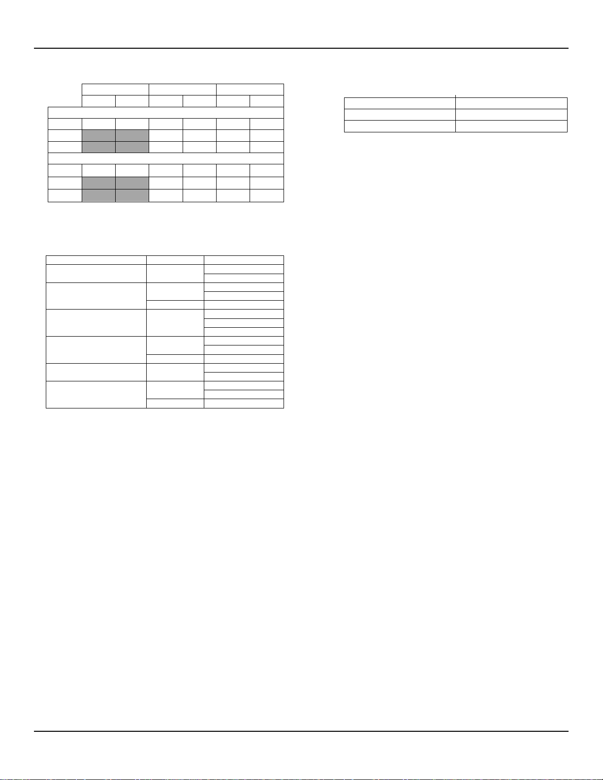
GENERAL ST80/ST80L Flow Meter
Tubing
Sch 40 Pipe
Sch 80 Pipe
psig
bar(g)
psig
bar(g)
psig
bar(g)
F Style Sensor
1"
2400
165
2500
172
3000
207
1½"
1750
121
2500*
172*
2"
1500
103
2250*
155*
S Style Sensor
1"
2400
165
2500
172
2500
172
1½"
1750
121
2"
1500
103
2250*
155*
Process Connection
Transmitter
Temp. Service1
Lo: 350 °F [177 °C] 2
Med: 500 °F [260 °C]
Lo: 350 °F [177 °C]
Med: 500 °F [260 °C]
Remote
Hi: 850 °F [454 °C]
Lo: 350 °F [177 °C]
Med: 500 °F [260 °C]
Hi: 850 °F [454 °C]
Lo: 350 °F [177 °C]
Med: 500 °F [260 °C]
Remote
Hi: 850 °F [454 °C]
Lo: 350 °F [177 °C]
Med: 500 °F [260 °C]
Lo: 350 °F [177 °C]
Med: 500 °F [260 °C]
Remote
Hi: 850 °F [454 °C]
1" to 6" [25 mm t o 152 mm]
1" to 12" [25 mm to 305 mm]
1" to 21" [25 mm to 533 mm]
1" to 36" [25 mm to 914 mm]
1" to 60" [25 mm to 1524 mm]
AC:
10 W, 1 Flow Element
DC:
9.6 W, 1 Flow Element
ST80L In-line Style
2500* 172*
* 1½" and 2" Sch 80 available by special order only; contact FCI.
¾" pipe also available by special order.
■ Operating Temperature (Process)
ST80 Insertion Style (FPC, FP, and S sensor head types)
Compression Fitting Integral/Remote
Low Pressure Packing Gland
Med. Pressure Packing Gland Remote
Fixed NPT
Fixed Flange (1" or DN25) Integral/Remote
Fixed Flange (≥1½" or ≥DN40)
Notes: 1. Minimum temperature is -40 °F [-40 °C].
2. For Teflon ferrule max. temper ature is 200 °F (93 °C).
Integral/Remote
Integral/Remote
Integral/Remote
ST80L In-line Style ( F and S sensor head types)
-40 °F to 257 °F [-40 °C to 125 °C]
■ Model ST80, Process Connections and Insertion Lengths
Compression Fittings: Model ST80 only
¾" or 1" male NPT, stainless steel with adjustable Teflon
ferrule or metal ferrule; or flanged tapped and threaded for ¾"
fitting, ANSI or DIN flanges.
Compression fittings not available with 850 °F [454 °C]
temperature versions of ST80.
Retractable Packing Glands
Low pressure 50 psig [3,5 bar (g)] or medium pressure 500
psig [34 bar (g)] with graphite or Teflon packing material; 1¼"
male NPT or ANSI or DIN flange.
Teflon packing required when process media is ozone, chlorine
or bromine. Remote mount required when medium pressure
packing gland is required.
Fixed Fittings/All Welded
1" male NPT, ANSI or DIN flange
Insertion Length
Field adjustable lengths:
Fixed lengths from 2.6" to 60" [66 mm to 1524 mm]
■ Model ST80L, In-line Flow Body and Process Connections
Flow element is calibrated and supplied as a spool-piece; options
include low flow injection tubes and built-in Vortab flow
conditioners for optimum low flow rangeability and performance
Size: 1" diameter tubing; 1", 1½", or 2" Schedule 40 pipe;
1" Schedule 80 pipe
Length: 9 nominal diameters
Process Connections: female NPT, male NPT, ANSI or DIN
flanges, or butt weld prepared
Option: Flanges sized for flow tube
■ Remote Transmitter Configurations
Transmitter may be mounted remotely from flow element using
interconnecting cable (up to 1000 ft [300 m]). Remote configuration required with selection of medium pressure packing gland.
Flow Transmitter/Electronics
■ Operating Temperature
-40 °F to 140 °F [-40 ° C to 60 °C]
■ Input Power
AC: 100 VAC to 265 VAC, 50 Hz to 60 Hz
DC: 24 VDC (19.2 – 28.8 volts)
■ Power Consumption
■ Battery Backup (for RTC)
Industrial-spec 3V Lithium coin cell type CR2450N
■ Outputs
Analog
Standard: Two (2) 4-20 mA outputs*.
4-20 mA outputs are user assignable to flow rate and tempera-
ture; outputs are user programmable to full flow range or subsets
of full flow range.
* Outputs are isolated and have fault indication per NAMUR NE43
guidelines, user selectable for high (>21.0 mA) or low (<3.6 mA)
HART (comes standard with analog outputs), V7 compliant.
Digital
Standard: USB (service and configuration port only); Modbus
RS-485
Optional: F
PROFIBUS DP.
FF Physical Parameters
Maximum Network Input Voltage - Ui (in V) = 32
Maximum Network Input Current - li (in mA) = 13
OUNDATION Fieldbus H1, PROFIBUS PA, or
4 Fluid Components International LLC
Page 13

ST80/ST80L Flow Meter GENERAL
■ Enclosures
Main Transmitter/Electronics:
NEMA 4X, IP66/67 polyester powder coated aluminum or
optional 316L stainless steel.
Four (4) cable ports ½"-14 NPT or M20 x 1.5
Size:
5" W x 5.40" H x 7.75" L (127 mm x 137 mm x 197 mm)
Local Enclosure (Remote Configuration):
• Single cable port enclosure (available with packing gland/low and
med press; ≥1.5" fixed flange; fixed NPT process connections):
NEMA 4X, IP66/67 polyester powder coated aluminum or
optional 316L stainless steel.
One (1) cable port 1"-11.5 NPT
Size: 4.68" W x 4.87" H x 5.4" L (119 mm x 124 mm x 137 mm)
• Dual cable port enclosure (available with compression fitting;
1" fixed flange process connections):
NEMA 4X, IP66/67 polyester powder coated aluminum or
optional 316L stainless steel.
Two (2) cable ports 1/2"-14 NPT or M20 x 1.5
Size: 3.27" W x 3.54" H x 3.9" L (83 mm x 90 mm x 99 mm)
■ Readout/Display (Option 1):
• Large backlit 2" x 2" [50 mm x 50 mm] LCD for display of digital
flow rate, analog bar graph of flow rate, total flow, and
temperature; user selectable engineering units, and alarm/fault
status indication.
• User programmable 17 alphanumeric character field
associated with each calibration group.
• Set-Up & Service mode displays text and service codes.
• Display is electronically rotatable in 90° increments to optimize
viewing angle.
Note: For units without the display option, the service port (USB)
lets a PC configure/manage the instrument via the ST80/ST80L
configurator utility.
Other Options
■ Vortab Flow Conditioners
Available for all line size applications; standard choice with Model
ST80L (in-line).
■ Sun Shield
Shades main transmitter, electronics, and display from direct
sunlight; 316L stainless steel.
FCI P/N 023241-01 Integral transmitter
FCI P/N 023237-01 Remote transmitter
■ Ball Valves/Cable Glands
■ Certification and Testing Documentation
CMTR, NACE, PMI, 0
hydrostatic or air pressure test, certificate of origin, certificate of
conformance, wake frequency strength, and more.
■ Field Service and Support
Start-up assistance, site commissioning and installation
validation, maintenance agreements, bus communications
integration and validation, and more.
cleaning, radiography, dye penetrant,
2
■ Readout/Display and Optical Touch Buttons (Option 2)
Includes the Readout/Display Option 1 items, plus adds four
keypad/buttons for the user interface.
• Four (4) optical touch buttons for user programming of
instrument set-up and service interrogation.
• User programming and setup via the front panel.
• Optical touch button activation through front window – no need
to open enclosure to access or activate.
• Set and adjust the meter or interrogate diagnostics in-situ,
even in HazEx installation.
Fluid Components International LLC 5
Page 14

GENERAL ST80/ST80L Flow Meter
This Page Intentionally Left Blank
6 Fluid Components International LLC
Page 15

ST80/ST80L Flow Meter INSTALLATION
Warnings:
2 INSTALLATION
● Consult the manufacturer if dimensional information on the flameproof joints is necessary.
● The ambient temperature range and applicable temperature class of the ST80/ST80L flow meter is based on the
maximum process temperature for a particular application. Refer to page 137 for details.
● The painted surface of an ST80/ST80L flow meter (aluminum housing only) can store electrostatic charge and become
a source of ignition in applications with a low relative humidity < 30% relative humidity where the painted surface is relatively
free of surface contamination such as dirt, dust, or oil. Clean painted surfaces using a damp cloth moistened with water only.
● Do not replace internal battery when an explosive gas atmosphere is present.
Instrument Identification and Outline Dimensions
APPENDIX A starting on page 93 provides outline dimensions and mounting bracket dimensions for all integral and remote mounted electronic
configurations. Verify all dimensions meet the application requirements before beginning the installation process.
ST80 Insertion Sensor Installation
The proper flow meter location in the process piping configuration is critical to the instrument’s ability to measure the process variables accurately.
FCI recommends 20 nominal pipe diameters upstream and 10 pipe diameters downstream of the instrument installation point for most applications.
These distances can be significantly reduced when the flow meter is combined with FCI’s flow conditioning technology (Vortab).
Insertion flow elements can be mounted into the process using several available customer selectable configurations; compression fitting mounted,
threaded or flanged packing gland mounted, and threaded or flanged fixed “U” length mounted process connections. The specific sensor process
connection is specified by the customer on the order information sheet (OIS).
Mount the flow element to the process piping per the application piping requirements. Orient the instrument so that the flow arrow etched on the
element matches the direction of the process flow with the reference flat parallel to flow within ±3° of rotation. Insert a flow element with variable
insertion length ½” inch past the centerline of the process pipe or tube with the flow direction arrow correctly aligned and leveled. After the flow element has been located correctly and tightened into place, verify that the process seal does not leak by slowly applying pressure until the maximum
operation pressure is applied. Check for leaks at the process connection boundary using standard leak detection methods.
Figure 1 below shows a properly mounted compression fitting process connection instrument.
Fluid Components International LLC 7
Figure 1 – Example Compression Fitting Process Connection
Page 16
INSTALLATION ST80/ST80L Flow Meter
Ferrule Material
Torque
Teflon
6 ft-lbs
316 SST1
65 ft-lbs
1
Note:
The metal ferrule configuration can only be tightened one time. Once tightened, the insertion length is no longer adjustable.
Compression Fitting
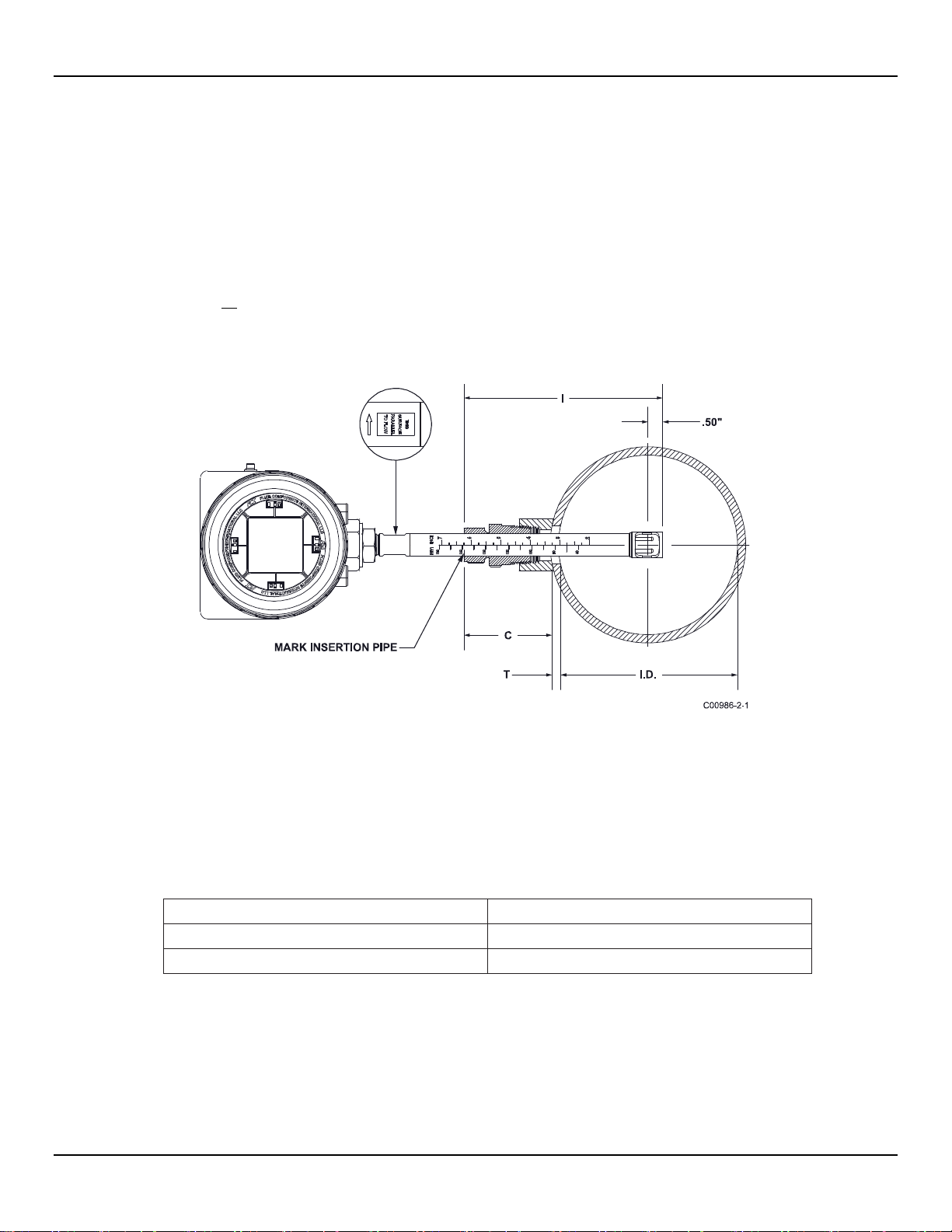
FCI single point insertion flow meters are calibrated at the centerline of the process pipe. The flow element is properly mounted when the
tip of the flow element is located 0.50 inches (13 mm) past the pipe centerline. See Figure 2 below. The scale etched on the side of the
insertion pipe indicates the length to the tip of the flow element. Follow the steps below to install the compression fitting flow element.
1. Calculate the insertion depth using the equation below.
I = Insertion depth
I.D. = Pipe inside diameter
T = Pipe wall thickness
C = Pipe mounting coupling and compression fitting (installed length)
..
= 0.50" +
I = __________
+ +
2. Mark the insertion pipe at the calculated insertion depth.
Figure 2 – Compression Fitting Installation, Dimensions
3. Apply proper thread sealant to the tapered pipe thread on the compression fitting and secure into pipe mounting coupling.
4. Insert the flow element to the insertion depth mark making sure the orientation flat is aligned parallel to the flow direction. Hand tighten
the compression nut. Compression fitting manufacturer recommends 1¼ turns past hand tight.
5. Tighten the compression nut to the torque specified for the corresponding ferrule material. See Table 1 below.
Table 1 – Compression Fitting Material
8 Fluid Components International LLC
Page 17
ST80/ST80L Flow Meter INSTALLATION
C00991-2-1
REMOTE ENCLOSURE
EXPLOSION PROOF
AGENCY APPROVED
FLANGE,
SIZE AND RATING
CUSTOMER SPECI FIED
FLAT TO SHOW
FLOW ORIENTATION
PIPE
PIPE
C00992-2-1
1" or 1¼" NPT
FLAT TO SHOW
FLOW ORIENTATION
0.50"
[12.6 mm]
Flange Mount
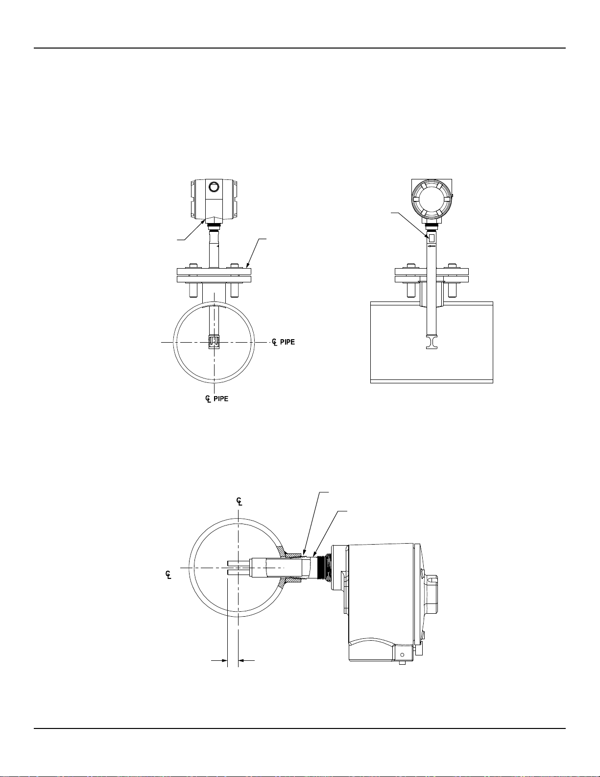
The flange mount flow element is shown in Figure 3 below. Attach the process mating flange with care. Correctly orient the flow element's
reference flat to ensure the instrument's calibrated accuracy.
● Verify the process media flow matches the flow direction arrow on the flow element.
● Apply appropriate gasket and or sealant to flange mount as required.
● Mate flow element flange to process flange keeping flat oriented properly.
● Secure flanges with appropriate mounting hardware.
Figure 3 – Example Flange Mount Installation
NPT Pipe Thread Mount
The pipe thread configuration is shown in Figure 4 below. Apply sealant compatible with the process media to male threads. Carefully insert into
process mounting coupling. Tighten the flow element until snug and continue until flat and flow direction arrow are aligned with process flow.
Figure 4 – Example NPT Pipe Thread Mount Installation
Fluid Components International LLC 9
Page 18
INSTALLATION ST80/ST80L Flow Meter
Retractable Packing Gland Mounting
A retractable low and medium pressure packing gland, with 1¼" MNPT threads or ANSI/DIN flange, and graphite or Teflon packing, is a
process connection option. FCI single point flow meters are calibrated at the centerline of the process pipe. The flow element is properly
mounted when the tip of the flow element is located .50 inches (13 mm) past the pipe centerline. Follow the below steps to install/retract
instruments with the retractable packing gland option (as applicable to your configuration, also follow the pipe thread or flange mount
procedures as described in previous sections).
Insertion/Installation Procedure
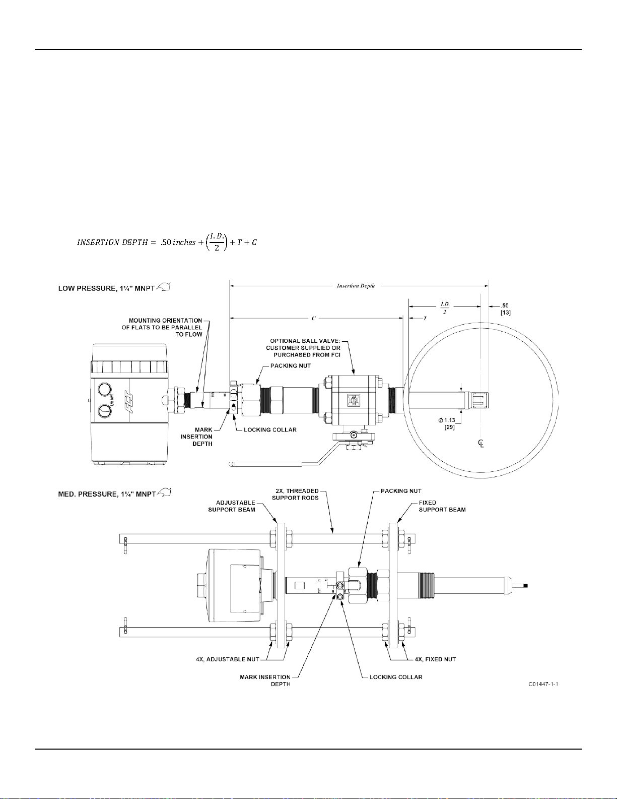
1. The scale etched on the side of the insertion probe indicates the length to the tip of the flow element. Calculate the insertion depth
using the equation, variables, and Figure 5 below.
ID
= Inside Diameter of Pipe
T
= Pipe Wall Thickness
C
= Mounting Coupling with Optional Ball Valve and Installed Packing Gland Length
INSERTION DEPTH = ______________
Figure 5 – Retractable Packing Gland Installation
10 Fluid Components International LLC
Page 19

ST80/ST80L Flow Meter INSTALLATION
Caution:
For applications where the process media is pressurized to greater than 50 psig (3.5 barg), a medium pressure
Warning:
Take note of your environment if using an electric drill to operate the retractor. Do not use an electric drill in an
Note:
After inserting the probe, you have the option to leave the retractor tool in place to ease future probe removal. If the retractor
2. Mark the insertion pipe at the calculated insertion depth.
3. Ball Valve Applications Only: If a ball valve is required, install the ball valve to the process mounting coupling. Close the ball valve
to prevent the process media from leaking out when installing the packing gland with the process line pressurized.
4. Apply the proper thread sealant compatible with the process media to the male threads of the packing gland. Fully retract the insertion
probe into the cavity of the packing gland and install the packing gland into the process mounting coupling or ball valve as described
in the previous sections: Flange Mount and NPT Pipe Thread Mount. If a ball valve is not used, make sure to first depressurize
the process line before installing.
5. Tighten the packing nut until the internal packing is tight enough to prevent excess process leakage, but also allow the insertion probe
to be inserted into place. For ball valve applications, open the ball valve after the packing nut has been tightened.
packing gland assembly with support rods or FCI retractor tool, part no. 026854-01, must be used to safely insert the
probe into the process. The FCI packing gland and retractor tool are rated to a maximum pressure of 500 psig (35
barg). For instructions on how to install the flow meter using the FCI retractor tool, see step 7.
6. Manual Flow Element Insertion: Insertion by Hand (Pressure: 50 psig [3.5 barg] max.) or Using Med. Pressure Packing Gland
Assembly with Support Rods (Pressure: 500 psig [35 barg] max.)
a. Align the orientation flat and flow arrow parallel to the flow direction and proceed to insert the flow element into the process
media pipe up to the insertion depth mark. For medium pressure packing gland, use the adjusting nuts on the threaded rods to
pull the flow element up to the insertion depth mark, and then tighten the adjustable nuts against the adjustable support beam to
lock the insertion probe into place. Make sure to move the adjustable nuts at the same time (equally) to prevent the probe from
bending and damaging the packing gland.
b. Tighten the packing nut another ½- to 1-turn tight (approximately 65-85 ft-lbs [88-115 N-m]) until the packing has created a full seal.
c. Ensure the locking collar is properly secured to the back of the packing gland. Torque the two ¼"-28 socket head cap screws on
the locking collar to 94 in-lbs [11 N-m} using a 3/16" hex key.
7. Flow Element Insertion Using FCI Retractor Tool 026854-01 (Pressure: 500 psig (35 barg) max.)
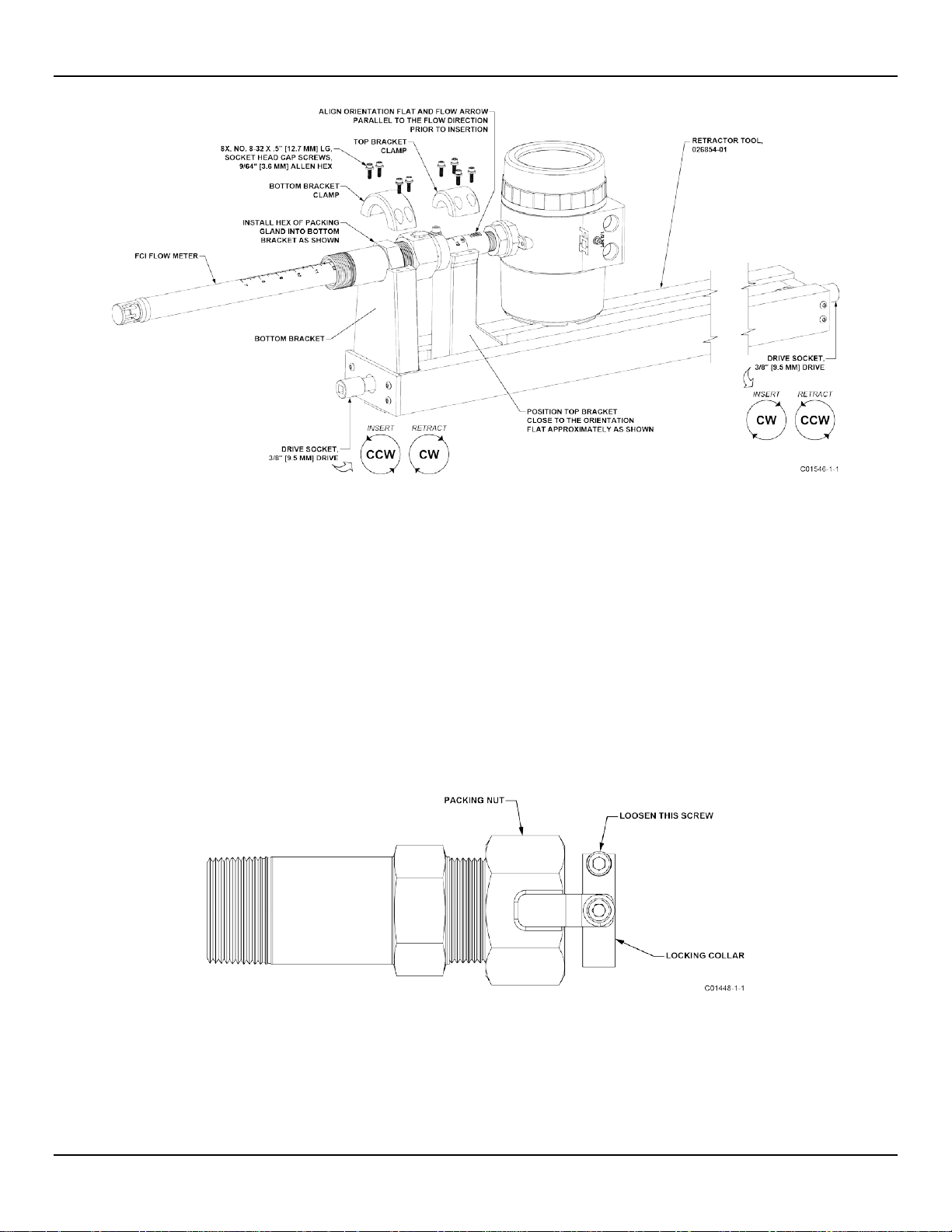
a. Place the flow element into the top and bottom brackets of the FCI retractor tool as shown in Figure 6.
b. Align the orientation flat and flow arrow parallel to the flow direction. Position the top bracket close to the orientation flat as
shown in Figure 6.
c. Secure the top and bottom bracket clamps to the flow element using the eight no. 8-32 screws provided as shown in Figure 6.
Torque these screws to 20 in-lbs [2 N-m] minimum.
d. The retractor tool has, on both ends, a 3/8" drive socket that engages the retractor to move the flow element in or out. Once the
flow element has been properly secured, open the ball valve and insert the flow element by using either a hand wrench or a drill
to rotate either drive socket in the appropriate direction for insertion as shown in Figure 6. Observe the Warning below if using
an electric drill. Insert the flow element up to the insertion depth mark and tighten the packing nut another ½ to 1 turn tight
(approximately 65 to 85 ft-lbs [88-115 N-m]) until the packing has created a full seal.
explosive environment as the drill could create a spark and cause an explosion.
e. Ensure the locking collar is properly secured to the back of the packing gland. Torque the two ¼"-28 socket head cap screws on
the locking collar to 94 in-lbs [11 N-m} using a 3/16" Allen wrench (hex key).
tool is removed, make sure to reinstall it before retracting the probe at pressures > 50 psi g. Since the packing gland itself
has a 500 psig rating, the probe remains securely in place with the retr ac tor off .
Fluid Components International LLC 11
Page 20
INSTALLATION ST80/ST80L Flow Meter
Caution:
Figure 6 – Flow Element Installation Using FCI Retractor Tool 026854-01
Retraction/Removal Procedure
For applications where the process media is pressurized to greater than 50 psig (3.5 barg), FCI retractor tool, part no.
026854-01, must be used to safely retract the probe from the process (does not apply to applications using the
medium pressure packing gland assembly with support rods). For applications where the process media is
pressurized to equal to or less than 50 psig (3.5 barg), the flow element can be safely guided by hand. When using
hands to restrain the retraction, be prepared for a rapid pressure impulse of the flow element. Check first that there
are no objects directly behind the flow element as the insertion probe may retract very quickly.
1. Manual Flow Element Retraction: Retraction by Hand (Pressure: 50 psig [3.5 barg] max.) or Using Med. Pressure Packing
Gland Assembly with Support Rods (Pressure: 500 psig [35 barg] max.)
a. Loosen the socket head cap screw on the side of the locking collar. See Figure 7 below.
Figure 7 – Packing Gland Locking Collar
b. Low Pressure (max. 50 psig [3.5 bar(g)]): Slowly loosen the packing nut until the insertion probe begins to retract. Use hands as
needed to help control the retraction. If the probe does not begin to retract itself, gently shake and pull the insertion probe until
the flow element has been fully retracted into the packing gland.
12 Fluid Components International LLC
Page 21

ST80/ST80L Flow Meter INSTALLATION
Warning:
Take note of your environment if using an electric drill to operate the retractor. Do not use an electric drill in an
Medium Pressure (max. 500 psig [35 bar(g)]): Loosen the two nuts at the top of the adjustable support rods so that they lie
slightly above the top support beam. Slowly loosen the packing nut until the insertion probe begins to retract. The insertion probe
will come to rest when the support beam at the top of the probe makes contact with the two top adjustable nuts. Continue to
slowly loosen the two top nuts until the insertion probe has fully retracted into the body of the packing gland. If the insertion probe
does not retract when moving the two top nuts, continue loosening the packing nut until retraction resumes. Make sure to move
the two top adjustable nuts at the same time (equally) to prevent the probe from bending and damaging the packing gland. To
lock the probe in a retracted state, tighten the top and bottom adjustable nuts against the top support beam.
c. For ball valve applications: Close the ball valve immediately after retraction to seal off the process. After closing the ball valve it
is then safe to remove the flow element from the back end of the ball valve. If a ball valve is not being used, make sure to
first depressurize the process line before removing the flow element.
2. Flow Element Retraction Using FCI Retractor Tool 026854-01 (Pressure: 500 psig (35 barg) max.)
a. Install the FCI retractor tool to the flow element as described in Insertion/Installation Procedure, page 10, steps ‘a,’ ‘b,’ and ‘c.’
b. Loosen the socket head cap screw on the side of the locking collar. See Figure 7 above.
c. Slowly loosen the packing nut until the load shifts to the top bracket of the retractor tool (approximately 1-1.5 turns).
d. The retractor tool has, on both ends, a 3/8" drive socket that engages the retractor to move the flow element in or out. Use a
hand wrench or a drill to rotate either drive socket in the appropriate direction for retraction as shown in Figure 6. Observe the
Warning below if using an electric drill. Retract the flow element until the sensor head has been fully retracted into the cavity of
the packing gland.
explosive environment as the drill could create a spark and cause an explosion.
e. Immediately after retraction, close the ball valve to seal off the process.
f. After the ball valve has been closed, it is safe to remove the flow element from the back end of the ball valve.
Fluid Components International LLC 13
Page 22
INSTALLATION ST80/ST80L Flow Meter
C00993-2-1
LINE SIZE "A" LENGTH
1" 9"
1½" 13.5"
2" 18"
FLOW DIRECTION
OPTIONAL
CUSTOMER
PROCESS
CONNECTIONS
BUTT WELD FEMALE NPT MALE NPT
OPTIONAL VORTAB
2x FLANGED
PROCESS CONNECTION
7x DIA.
2x DIA.
ST80L In-Line Process Connection
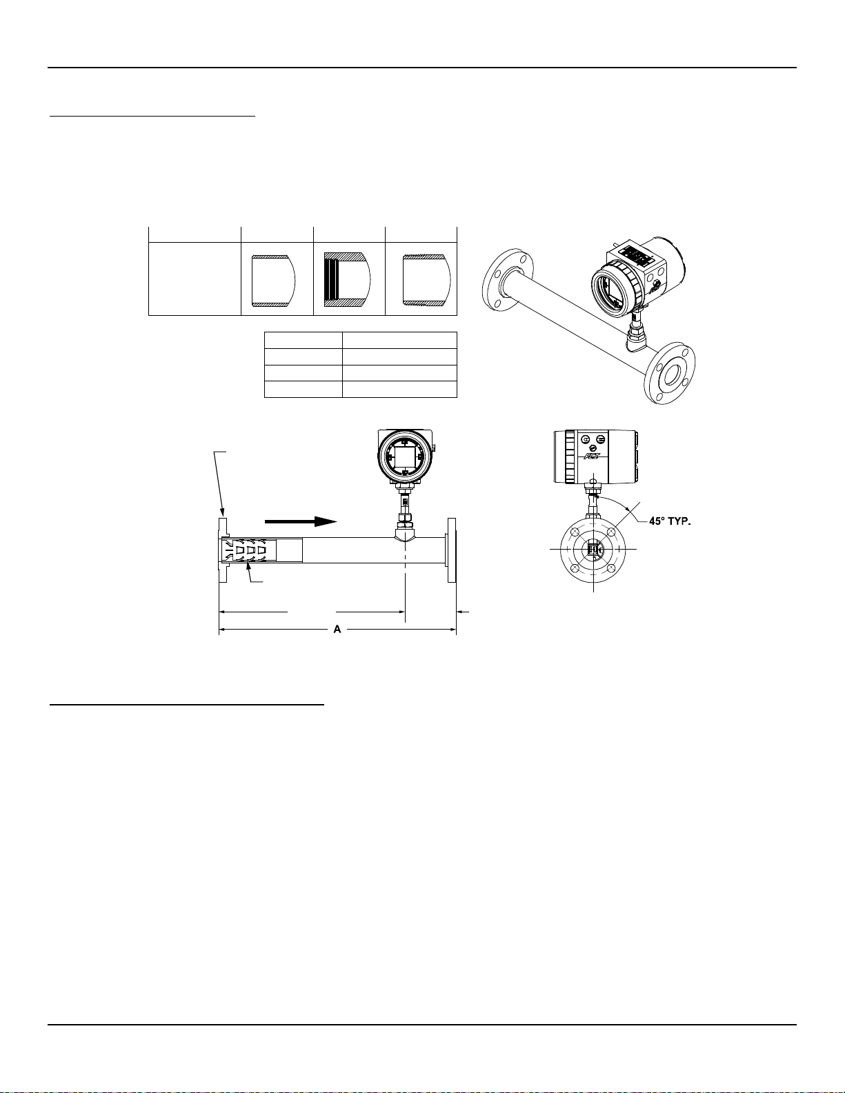
The in-line ST80L flow element assembly can be threaded, flanged or butt weld mounted to the process piping. The specific type in-line process
connection is customer-specified on the order information sheet (OIS). See Figure 8 below.
Mount the sensor to the process piping per the application piping requirements. Verify the flow direction arrow is pointed in the correct direction. After
the sensor head has been located correctly and tightened into place, verify the process seal does not leak by slowly applying pressure until the
normal operation pressure is applied. Check for leaks at the process connection boundary.
Figure 8 – ST80L Process Connection
Installation of Probe with Moisture/Rain Shield
14 Fluid Components International LLC
For sensor probes equipped with a moisture or rain shield, position the probe/shield assembly within the pipe as shown in Figure 9. The
drawing shows the orientation of the moisture/rain shield relative to the flow direction, the correct position of the probe/shield assembly
relative to the pipe centerline, and the minimum pipe size. The moisture shield prevents build-up of moisture in the sensor head for wet gas
applications. The rain shield shields the sensor from rain falling into an open vertical pipe/stack in upward vertical flow applications.
Page 23

ST80/ST80L Flow Meter INSTALLATION
Figure 9 – Installation of Sensor Probe with Moisture/Rain Shield
Fluid Components International LLC 15
Page 24
INSTALLATION ST80/ST80L Flow Meter
Caution:
FCI flow meters contain static-sensitive devices. To avoid damage to the instrument observe the ESD precautions
C00988-2-2
Flow Transmitter Electronics Installation
The instrument electronic transmitter can be an integral part of the flow element or it can be mounted remotely using a shielded cable between the
flow element and the electronics.
Use power wiring with a minimum 90 °C rating.
ESD Precautions
listed below before opening the instrument for wiring.
● Use a wrist band or heel strap with a 1 MΩ resistor connected to ground.
● Use a static conductive mat on the work table/floor with a 1 MΩ resistor connected to ground when working on the instrument in a shop setting.
● Connect the instrument to ground.
● Apply antistatic agents such as Static Free made by Chemtronics to hand tools used on the instrument.
● Keep high static-producing items away from the instrument.
The above precautions are minimum requirements. The complete use of ESD precautions can be found in the U.S. Department of Defense
Handbook 263.
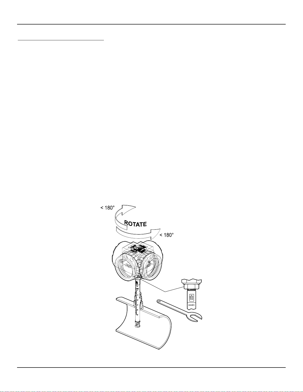
Integral Electronics
The integral electronics package is mounted during the flow element installation process. The integral electronics can be rotated ±180
degrees on the top of the flow element insertion pipe. This is done by loosening the lock nut at the base of the enclosure and rotating the
enclosure to the preferred orientation. Do not rotate the electronics enclosure more than ±180 degrees. Damage to internal wiring
may result from over-rotating the enclosure.
Lock Nut Torque Specification: 30-35 ft-lbs (40-47 N-m)
Provide integral electronics with additional support/bracing in applications where excessive vibration is present. A mounting bracket is
available from FCI to support the electronics when additional support is required. See Figure 10 below.
Figure 10 – Integral Electronics Installation (Compression Fitting Shown)
16 Fluid Components International LLC
Page 25

ST80/ST80L Flow Meter INSTALLATION
Remote Electronics
A mounting bracket is supplied when the transmitter is ordered for remote mounting. The bracket mounting details are shown in Figure 11
below. Refer to the outline installation drawings in Appendix A for additional mounting details. The electronics can be easily mounted on a
wall or pipe. The mount bracket is designed for .25 inch or M6 mounting hardware. Securely mount the electronics to cement or structural
support columns or beams. Mounting to plaster is not recommended and does not meet system approval requirements.
Figure 11 – Remote Installation, Mounting Bracket on Wall
Fluid Components International LLC 17
Page 26
INSTALLATION ST80/ST80L Flow Meter
2" Pipe
2x 3/16"-16
U BOLTS, SST
2x M4 SCREWS
(FCI PROVIDED)
ALUMINUM BRACKET
(FCI PROVIDED)
4x 3/16" HEX NUT
ST100A SERIES
TRANSMITTER
Remote Pipe Mounting
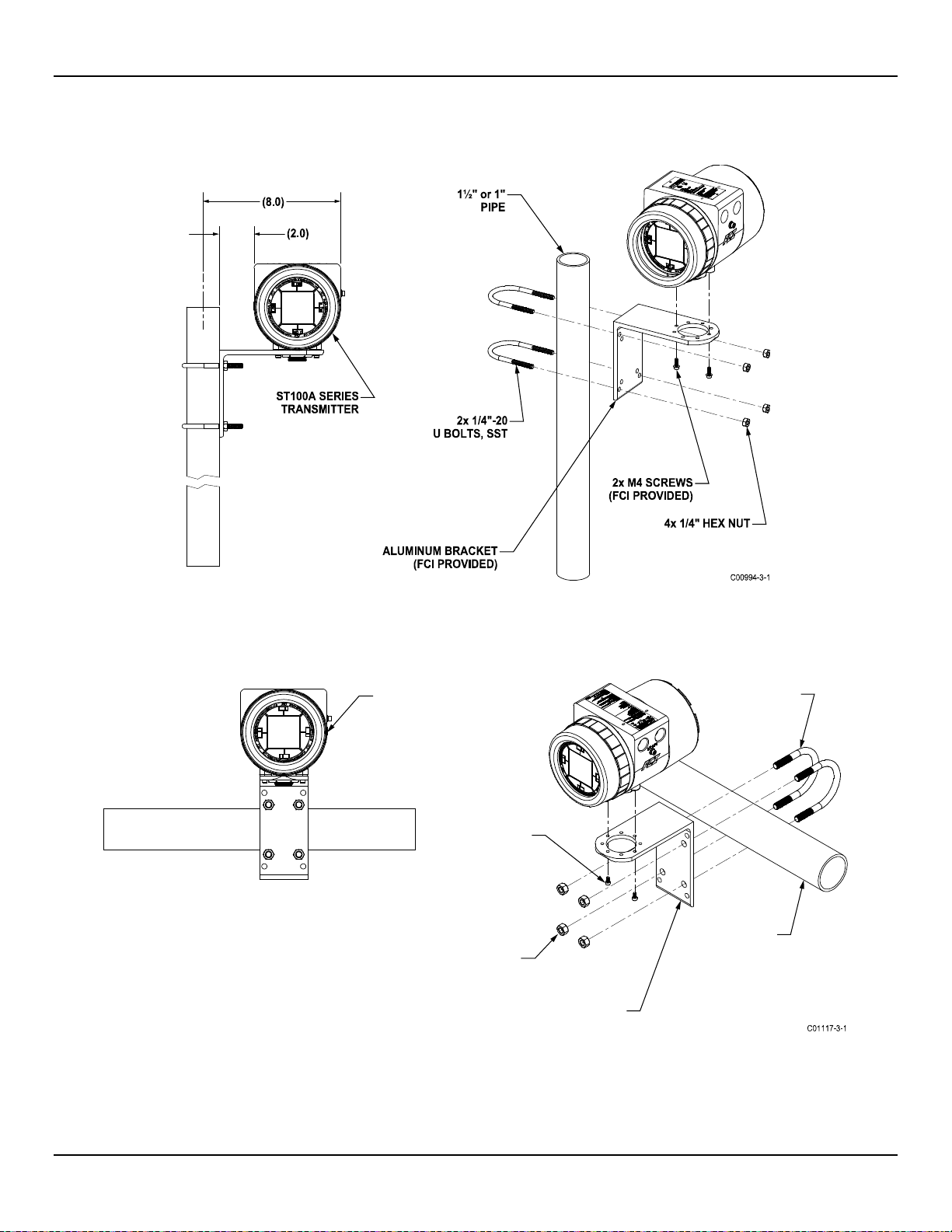
Refer to the figures below for remote transmitter pipe mounting details.
Figure 12 – Remote Installation, Mounting Bracket on 1" – 1½" Pipe
Figure 13 – Remote Installation, Mounting Bracket on 2" Pipe
18 Fluid Components International LLC
Page 27
ST80/ST80L Flow Meter INSTALLATION
C01247-2-1
2x M4 SCREWS
(FCI PROVIDED)
2x ¼"-20
U BOLTS, SST
4x ¼" HEX NUT
2" PIPE
ST100A SERIES
TRANSMITTER
(4.25)
(9.25)
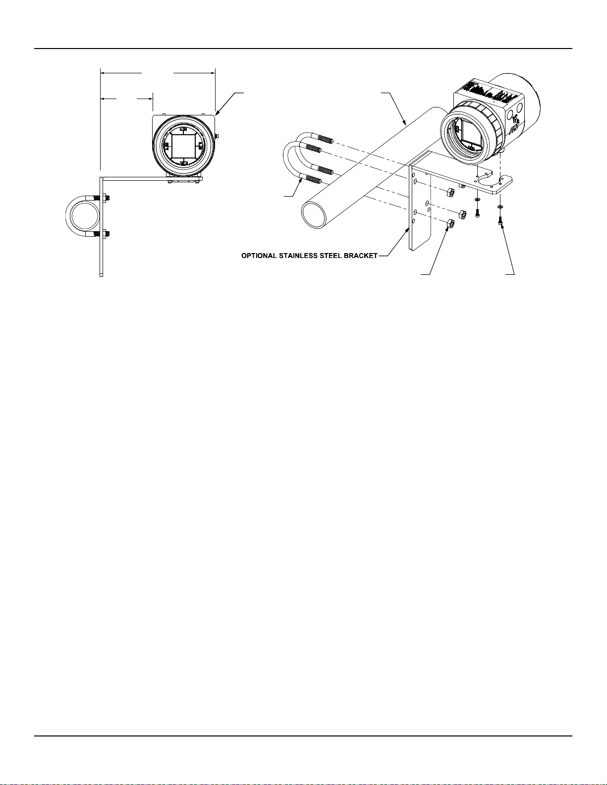
Figure 14 – Remote Installation, Optional Stainless Steel Bracket on 2" Pipe
Fluid Components International LLC 19
Page 28
INSTALLATION ST80/ST80L Flow Meter
Maximum Distance for AWG [mm2]
10 ft. (3 m)
50 ft. (15 m)
100 ft. (30 m)
250 ft. (76 m)
500 ft. (152 m)
1000 ft. (305 m)
Power AC or DC
22 [0.3255]
22 [0.3255]
22 [0.3255]
20 [0.5176]
18 [0.8230]
16 [1.3087]
Flow Element
(8-Cond. Shielded)
STP Flow Element
(10-Cond. Shielded)
16-30
16-30
16-30
16-30
16-30
16-30
Modbus
RS485 (14-30 AWG) [2.0809-0.0509]
F
Fieldbus
FF-844 H1 (14-30 AWG) [2.0809-0.0509]
PROFIBUS
RS485 (14-30 AWG) [2.0809-0.0509]
C01430-1-1
POWER CABLE/WIRING
SENSOR CABLE( S)
(REMOTE)
CUSTOMER I/O
CABLES/WIRING
Instrument Wiring
The flow transmitter can be powered by 85 – 265 VAC or 24 VDC as specified in the instrument
specification.
The electronics cannot be configured to
switch between AC and DC power. F or 220/265 VAC installations, a neutral reference circuit must be used.
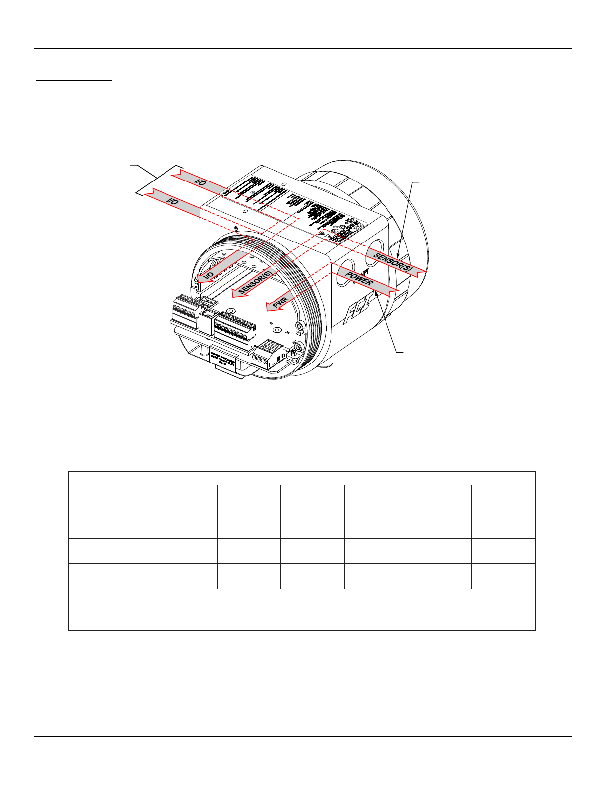
All cable glands and conduit fittings must meet or exceed the area approval rating where the instrument is being installed. The base electronics
enclosure has two wiring ports (1/2"-14 NPT or M20 x 1.5) on both sides of the enclosure body (local enclosure options excluded). The
recommended instrument wiring routing is shown in Figure 15 below.
Figure 15 – Recommended Wiring Routing, Base Electronics Enclosure
Table 2 below shows the smallest copper wire (maximum AWG number) that can be used for the listed cabling. Contact FCI concerning greater
distances than those listed in the chart. Refer to APPENDIX A, page 93 for additional wiring/cabling information.
Table 2 – Interconnecting Cable Minimum Conductor Size
Connection
24 [0.2047] 24 [0.2047] 24 [0.2047] 22 [0.3255] 22 [0.3255] 18 [0.8230]
22 [0.3255] 22 [0.3255] 22 [0.3255] 22 [0.3255] 22 [0.3255] 18 [0.8230]
Analog Out (HART)
OUNDATION
Notes: 1. Requires a shielded cable. The shield is connected to the GND in the transmitter enclosure. The other end of
the shield is left floating (no connection to the flow element enclosure).
2. Transmission speed determines maximum cable length and vice versa: 9.6 kbps = 3940 ft/1200 m, 19.2 kbps = 3940 ft/
1200 m, 45.45 kbps = 3940 f t/120 0 m, 93.75 kbps = 3940 ft/1200 m, 187.5 kbps = 3280 ft/1000 m, 500 kbps = 1310 ft/
400 m, 1500 kbps = 656 ft/200 m, 3000 kbps = 328 ft/100 m , 6000 kbps = 328 ft/100 m, 12000 kbps = 328 ft/100 m.
[1.3087-0.0509]
[1.3087-0.0509]
[1.3087-0.0509]
[1.3087-0.0509]
[1.3087-0.0509]
[1.3087-0.0509]
20 Fluid Components International LLC
Page 29
ST80/ST80L Flow Meter INSTALLATION
Warning:
Turn instrument power OFF before wiring the instrument.
Caution:
Use caution inserting wires into electronics housing. The metal ends can damage circuit boards.
Caution:
C01429-1-1
BLIND LID
LOCKING SET SCREW
WINDOW LID
LOCKING SET SCREW
INPUT
POWER, P1
FUSE
(Underneath)
SENSOR 1 CONNECTOR,
TB1
POWER SUPPLY COVER
USB TYPE B (PC CO NFIG),
J21
POWER SUPPLY
BOARD
OPT. FIELDBUS/
ADD-ON CARD
HART/4-20 mA CH. 1 OUT/
J25
Modbus/PROFIBUS/Fieldbus,
J8
MAIN BOARD
SYSTEM STATUS LED,
D3
Accessing the I/O Connectors
Remote Units: Avoid pulling, or inadvertently tugging, the remote cable when wiring the instrument. The sensor
connector/circuit board can be easily damaged by excess pulling of the remote cable.
Observe ESD precautions when wiring the instrument. Refer to ESD Precautions, page 16.
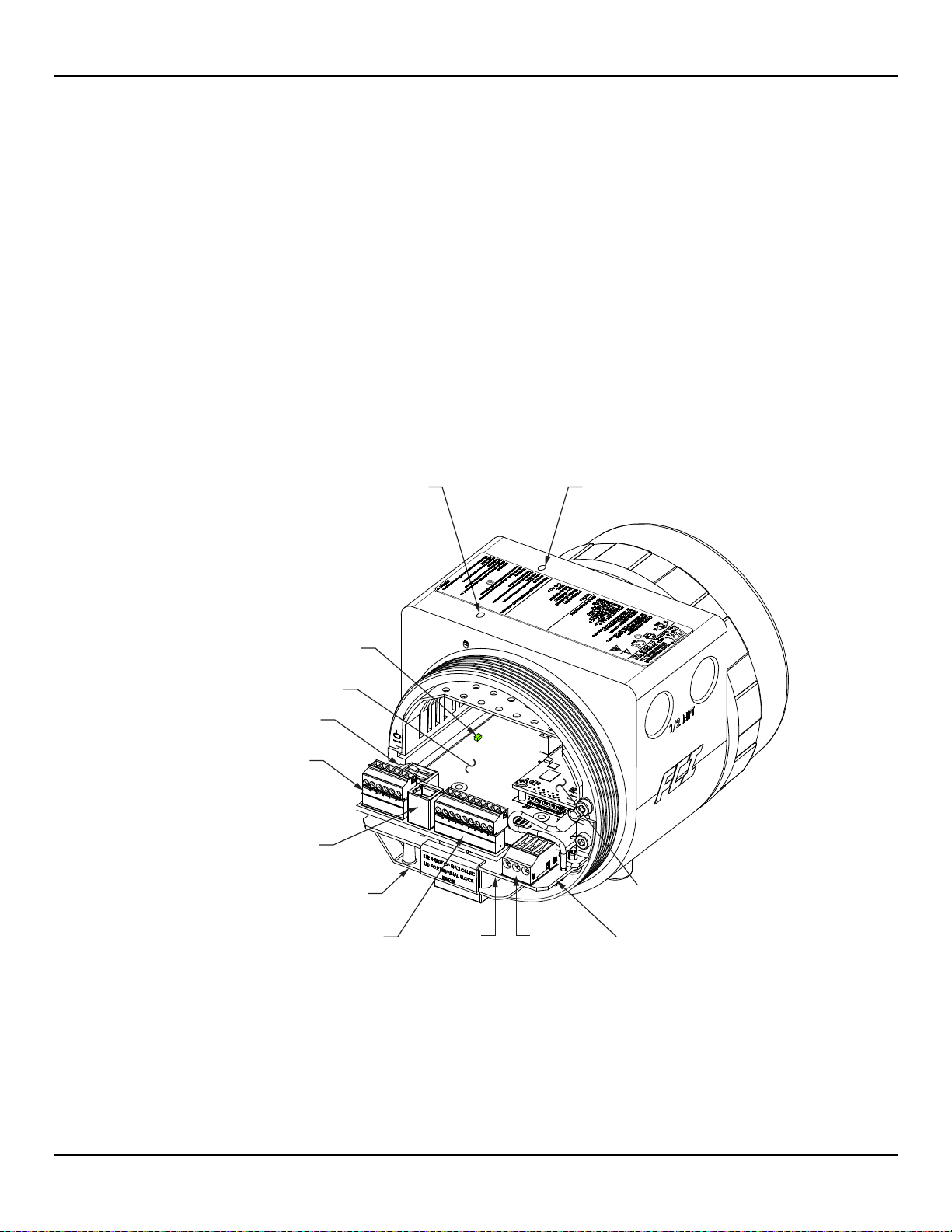
To access the instrument’s connection terminals first use a .050″ hex key to loosen the set screw locking the enclosure body blind lid. Then
unscrew the blind lid from the enclosure. Carefully pull the power and signal wires through the port to avoid damaging the electronics.
Figure 16 below shows the location of the ST80/ST80L I/O connectors as well as the lid set screw access holes in the enclosure body.
Connect wiring as described in the following paragraphs. Reinstall the blind lid when done making the connections: Tighten the lid one full
turn past the point where the O-ring makes contact with the lid, and then tighten the lid set screw to lock the lid (set screw must not
protrude from its threaded hole after tightening).
4-20 mA CH. 2 OUT,
Figure 16 – ST80/ST80L I/O Connector Locations
Fluid Components International LLC 21
PROFIBUS
Page 30
INSTALLATION ST80/ST80L Flow Meter
C01419-1-1
J9
J12
J13
J10
J11
T1
J8
J25
J21
TB1
J11
J10
J9
J12
J13
J12
J13
MAIN BOARD
MODBUS FF/PROFIBUS
LINE PULLDOWN
LINE PULLUP
#SIM_ENABLE
#NV_ERASE
#HW_LOCK
ATION
POWER SUPP LY BOARD
(Under Main Board)
1
2
3
1
2
3
1
2
3
ON POSITION
ACTIVE WHEN ON
LINE CONFIG. BUS SELECT, J8 FF/PROFIBUSADD-ON CARD
DIAG/TEST
1
2
3
DC Version
Power Labeling
Electronics Enclosure Label
Affixed to the inside of the blind lid is a label that identifies the ST80/ST80L’s jacks and connectors (with terminal assignment). See Figure
17 below. Use this label as a guide when wiring the instrument. Note that the PCB silkscreen also provides connector identification.
Figure 17 – ST80/ST80L Electronics Enclosure Label
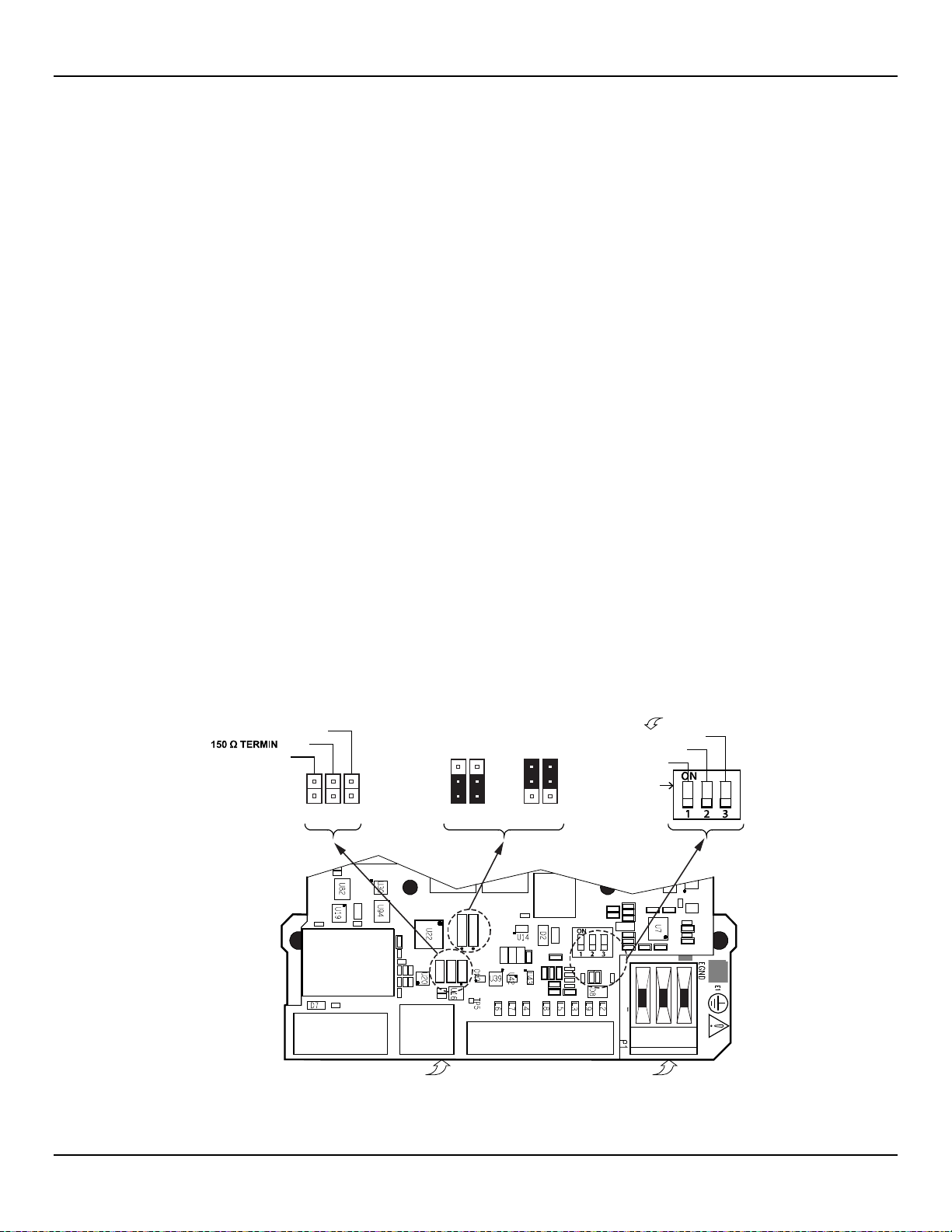
Configuration Jumpers/DIP Switch
When wiring the instrument for Modbus/Fieldbus/PROFIBUS make sure that the instrument is properly configured as shown in Figure 18
below. Refer to Modbus Connections on page 27 and Foundation Fieldbus/PROFIBUS Connections (Option) on page 28 for details.
Figure 18 – Bus Configuration 2 mm Jumper Headers and DIP Switch
22 Fluid Components International LLC
Page 31
ST80/ST80L Flow Meter INSTALLATION
Warning:
Install an AC line disconnect switch with fuse or breaker between the power source and the flow meter.
C01412-1-1
J9
J12
J13
J10
J11
T1
J8
J25
J21
TB1
1 2 3
Term. 1
Term. 2
Term. 3
Line
AC DC
DC+
Neutral DC–
E. Gnd E. Gnd
C01446-1-2
ACTerm #
DC
DC+
Line1
Neutral2
E. Gnd
3 E. Gnd
FERRITE CORE
1. Strip ends of power leads.
POWER
FERRITE CORE
terminal bloc k)
POWER CABLE/
POWER WIRING
MAIN BOARD
POWER
POWER SUPPLY
GROUND WIRE
AC Power = 85 VAC min. to 265 VAC max.
Input Power
Always disconnect power before performing maintenance on wiring.
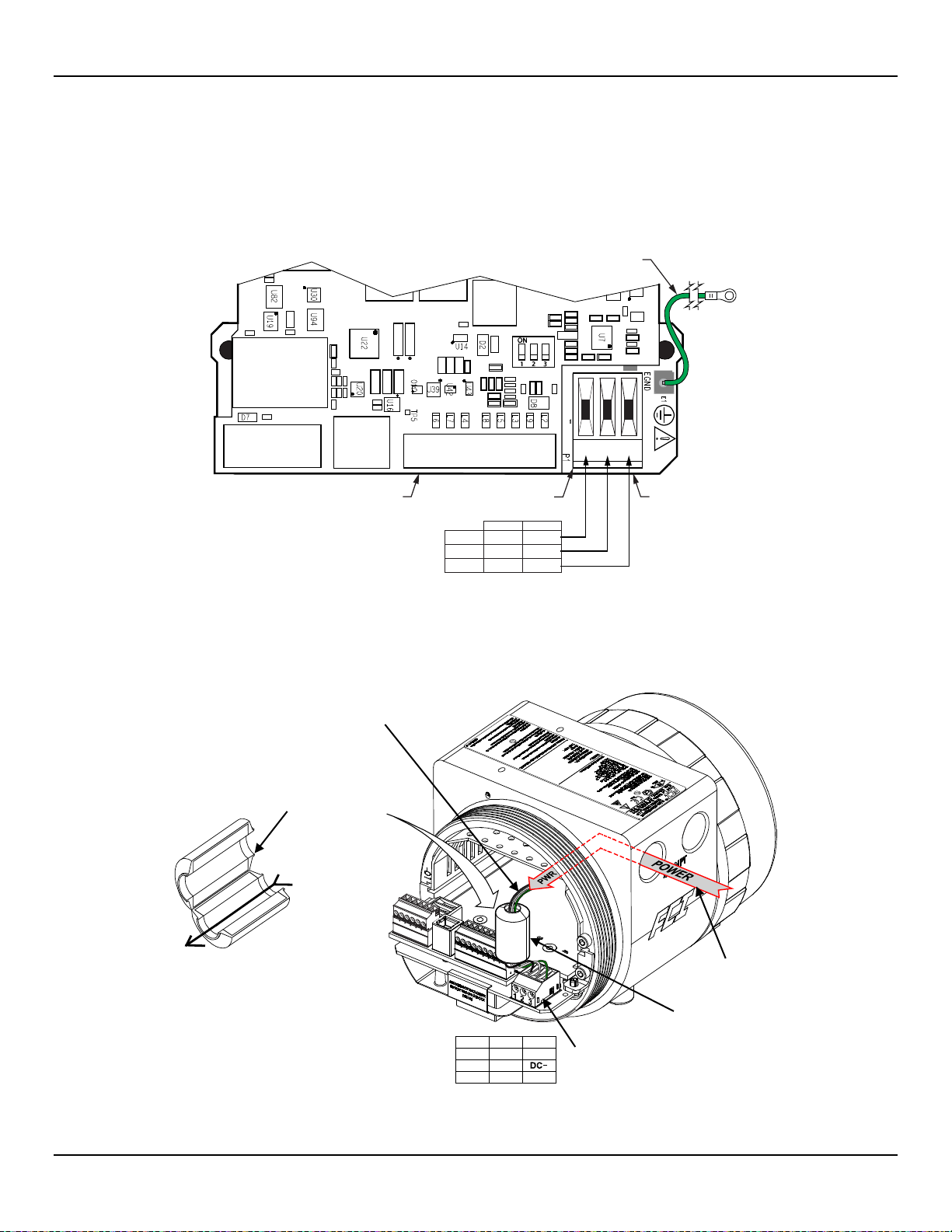
Connect input power to the 3-position Phoenix connector P1 on the power supply board as shown in Figure 19 below. The power
connector accepts 24–12 AWG (0.2 mm2 – 1.5 mm2) wire (refer to Table 2, page 20 for wire size vs. length info). It is recommended that
wiring have a flammability rating of UL 2556 VW-1 or equivalent.
(WITH RING LUG)
CONNECTOR, P1
BOARD
(Under Main Board)
DC Power = 19. 2 VDC min. to 28.8 VDC max.
Figure 19 – Input Power Wiring
Before connecting the power wires to connector P1, install the ferrite core clamp onto the power wiring as shown in Figure 20 below. Then
insert the stripped power wire ends into the appropriate P1 connector terminals. The ferrite core clamp (supplied with the instrument as
ferrite kit FCI p/n 023638-02) protects the instrument against the adverse effects of EMI/RFI electrical noise.
(AC Shown)
(3 power leads,
straight through)
2. Thread power leads t hr ough ferrite core (or snap open and
place wires in channel, and then snap core closed).
3. Insert power wires in appropriate P1 connector term inals.
See table/figure at right.
CONNECTOR, P1
4. Position ferrite core as close as possible to P1 connect or .
Figure 20 – ST80/ST80L Ferrite Core Installation
Fluid Components International LLC 23
WIRING
(Place close t o
Page 32
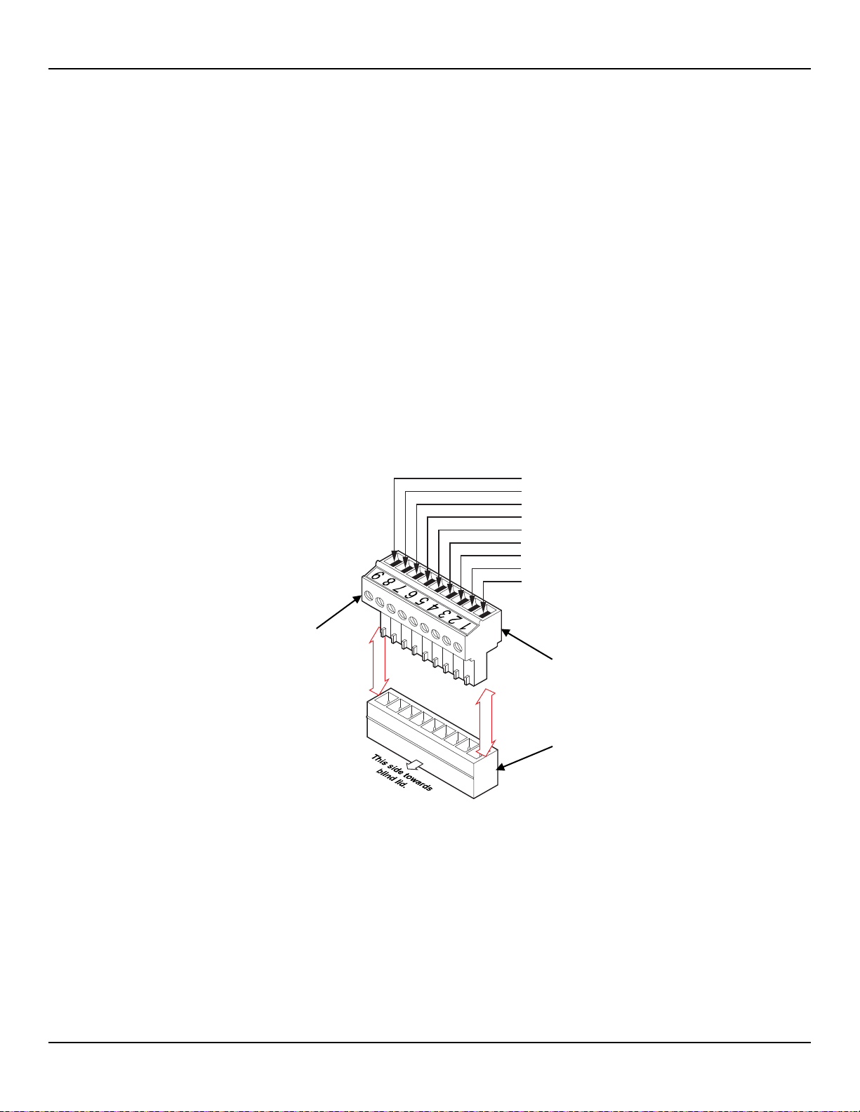
INSTALLATION ST80/ST80L Flow Meter
Note:
The flow element in all integral units is pre-wired at the factory. The information in this section applies to remote
C01431-1-1
1. HTR EXC #1
2. HTR RTN
3. ACT EXC
4. ACT SEN
5. GND SEN
6. GND
7. REF EXC
8. REF SEN
9. SHIELD
TB1, MAIN BOARD
DETACHABLE
PLUG
HEADER
SOCKET
Power overload protection is provided by a clip-mounted SMT fuse. Refer to Power Fuse Replacement, page 78 (MAINTENANCE section)
for fuse replacement details.
Flow Element Connections
configuration units only.
See the appropriate wiring diagram in APPENDIX A for interconnect wiring between the flow element and remote electronics. Use an 8conductor shielded cable for the external flow element input. The flow meter will not operate properly without these connections. To avoid
inaccurate flow meter readings make sure the ACT and REF wires are not reversed.
Referencing Figure 16 connect the ST80/ST80L flow element sensor wires to the detachable 9-position connector plug TB1 on the main
2
board. See Figure 21 below. The connector plug accepts 28-16 AWG (0.14 mm
- 1.5 mm2) wire (refer to Table 2, page 20 for wire size vs.
length info). Connect the flow element cable shield to the connector plug’s GND terminal (terminal #9). Leave the other end of the shield
floating (no connection to the flow element enclosure).Connect the flow element sensor to the plug as follows:
1. Remove connector plug from board (pull straight out).
2. Route sensor wires through remote enclosure’s wiring port/cable gland. Refer to Figure 15, page 20.
3. Strip wire ends (0.27 in [7 mm]) and insert into appropriate plug terminals as shown in Figure 21 below. Make sure to tighten each
terminal screw securely (max. torque: 2.2 inch-lbs [0.25 N-m]).
4. After all terminations are made plug connector block back into its header socket on the board.
Figure 21 – Flow Element Connections, TB1
24 Fluid Components International LLC
Page 33
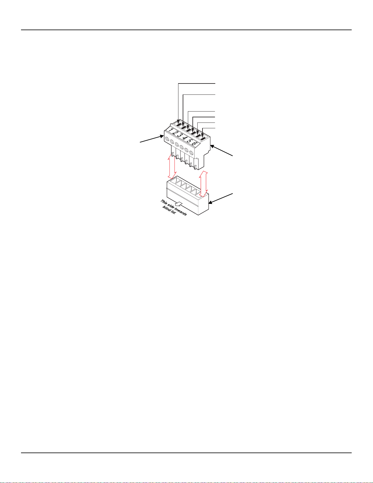
ST80/ST80L Flow Meter INSTALLATION
Note:
The HART communications digital signals are superimposed on top of the channel #1 current loop (4-20 mA) output.
C01459-1-1
6.
5.
4.
3.
2.
1.
Return (RTN)
Ext HART– (RTN)
Ch. 2 4-20 mA Return
Ch. 2 4-20 mA
Ch. 1 4-20 mA Return,
Int HART– (RTN),
Ext HART+
Ch. 1 4-20 mA,
Int HART+
J25, MAIN BOARD
DETACHABLE
PLUG
HEADER
SOCKET
HART Connections
Referencing Figure 16 connect the installation HART wiring to the J25 Phoenix connector. Similar to flow element connector TB1 the J25
connector is a detachable plug that plugs into the header socket on the board. Use the appropriate J25 connector terminals depending on
2
your application as shown in Figure 22 below. The connector plug accepts 28-16 AWG (0.14 mm
- 1.5 mm2) wire.
Figure 22 – HART and Ch. 1 & Ch. 2 4-20 mA Connections, J25
● Single Connection – The instrument supplies power to the loop and controls the current as well. For this application connect HART+
to J25-1 (INT HART+) and HART- to J25-2 (CH1/INT HART RTN). This is the default 4-20 mA Ch. 1 output even if HART is not used.
● Network (Multidrop) Connection – The instrument receives loop power from the network, and controls the current. For this
application connect external HART+ to J25-2 (EXT HART+) and external HART- to J25-4 (EXT HART RTN).
The block di ag ram in Figure 23 below shows the single connection and multidrop HART setups. Use a 250 Ω 1%, ≥ 0.3 W resistor as shown in the
diagram below only if the external HART interface/wiring does not have this resistance built-in (HART requires a minimum loop resistance of 230 Ω).
ABLING RECOMMENDATION
C
Use a shielded, twisted-pair instrument grade wire (min. 24 AWG for runs less than 5000 ft/1500 m; min. 20 AWG for longer distances). The RC
value of the wire (Total Resistance x Total Capacitance) must be less than 65 µs (not a concern for point-to-point topology with a run less than
328 ft/100 m). A cable designed for HAR T/R S-485 such as Belden 3105A is recommended for com plex set ups or particularly long runs or both.
When HART communications is in use, the HART current loop channel #1 MUST be configured as FLOW to comply
with the HART protocol. The channel #1 current loop output is configured as FLOW by default at the factory.
Fluid Components International LLC 25
Page 34
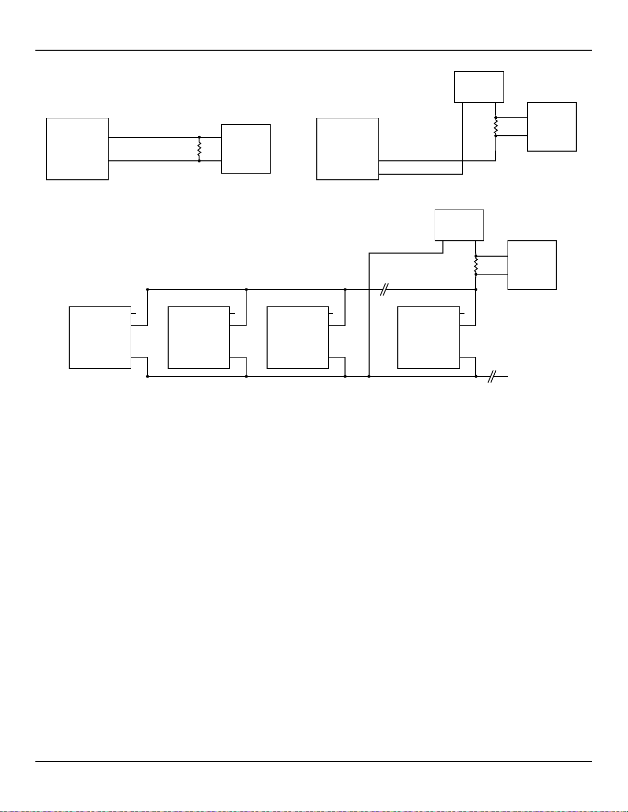
INSTALLATION ST80/ST80L Flow Meter
C01433-1-1
ST80/ST80L
HART
ST80/ST80L
J25-1
J25-2
HART
Internal Loop Power External Loop Power
+
–
J25-1
J25-2
J25-4
HART
R
ST100A
HART
I/O
LOAD
J25-1
J25-2
J25-4
HART
Master
ST80/ST80L
HART
(a) HART Single Connection
J25-1
J25-2
ST100A
HART
J25-4
J25-1
J25-2
J25-4
NC
+
–
ST100A
HART
Network P.S.
24 VDC
HART+HART–
Network P.S.
24 VDC
HART+HART–
J25-1
J25-2
J25-4
R
HART
LOAD
I/O
R
HART
LOAD
I/O
HART
Master
HART
Master
(b) HART Network, Multidrop
Figure 23 – Single Connection and Multidrop HART Setups
4-20 mA Output Connections
The ST80/ST80L is provided with two 4-20 mA current loop channels as standard via the J25 Phoenix connector terminals. Refer to Figure
16 and Figure 22. Similar to flow element connector TB1 the J25 connector is a detachable plug that plugs into the header socket on the
board. The connector plug accepts 28-16 AWG (0.14 mm
Ch. 1 is dedicated to HART (see above for connection details). Connect the instrument’s second 4-20 mA output (Ch. 2, J25-3) as required
for your application. Use any RTN terminal (e.g., J25-4 through J25-6) for the 2nd channel current loop return.
2
- 1.5 mm2) wire (refer to Table 2, page 20 for wire size vs. length info).
26 Fluid Components International LLC
Page 35
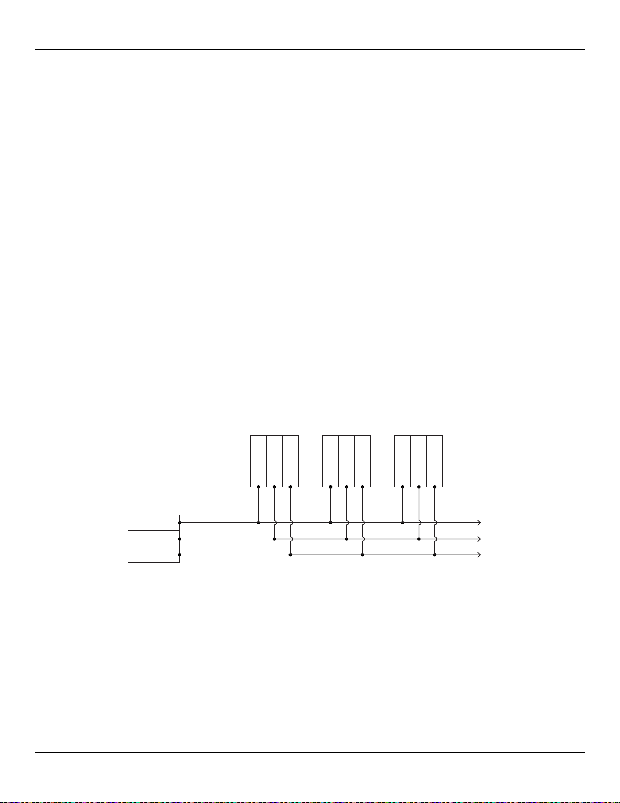
ST80/ST80L Flow Meter INSTALLATION
RS-485 MASTER
2-WIRE ONLY DEVICE
DEVICE 1 DEVICE 2 DEVICE 3
One twisted wire pair
plus Gnd/Common.
To remaining
RS-485 Devices
DATA (B)+
DATA (A)-
GND
DATA (B)+
DATA (A)-
GND
DATA (B)+
DATA (A)-
GND
DATA (B)+
DATA (A)-
GND
C01415-1-1
Modbus Connections
Referencing Figure 16 connect the Modbus device/network to Phoenix connector J8 on the main board. Note that the J8 connector is also
used for F
accepts 24–12 AWG (0.2 mm
OUNDATION Fieldbus and PROFIBUS wiring (only one interface can be active at a time). See Figure 24 below. Connector J8
2
– 1.5 mm2) wire (refer to Table 2, page 20 for wire size vs. length info). It is recommended that wiring have
a flammability rating of UL 2556 VW-1 or equivalent.
Figure 24 – Modbus/PROFIBUS/Fieldbus Connections, J8
Connect the ST80/ST80L to a Modbus device/network using a 2-wire RS-485 connection scheme as shown in Figure 25 below. For details
on Modbus operation refer to Modbus Operation, page 70.
Figure 25 – Modbus Wiring
Fluid Components International LLC 27
Page 36
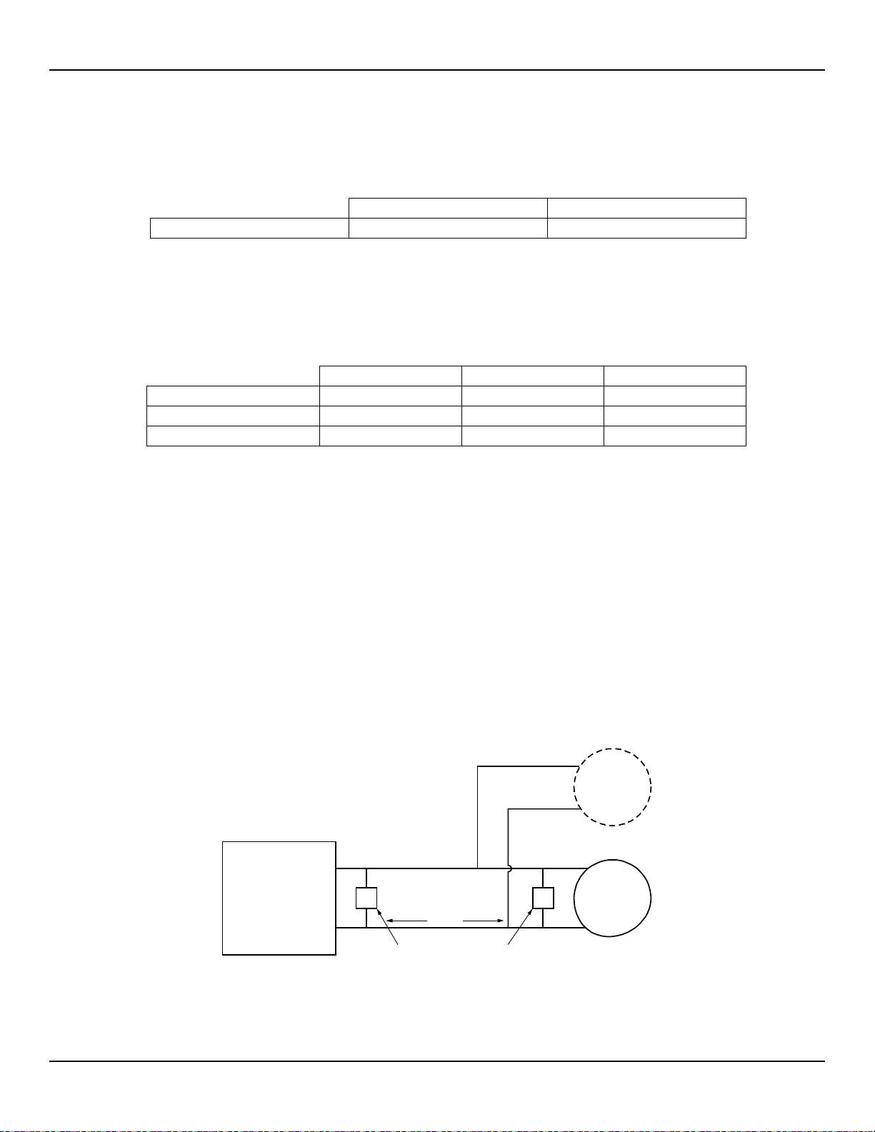
INSTALLATION ST80/ST80L Flow Meter
J12
J13
Install Jumper Shunt over Pins
1 and 2
1 and 2
J9
J10
J11
Line Biasing (pullup)
●
—
—
150 Ω Termination
— ● —
Line Biasing (pulldown)
— — ●
Note:
Foundation Fieldbus/PROFIBUS operation is provided through an optional add-on card that plugs into the
ST80/ST80L
Fieldbus/
PROFIBUS
Interface (J8)
Field
Device
Add’l
Field
Device
Wire Pair
FB_A
FB_B
Terminator Terminator
Signals
TT
C01432-1-1
Modbus Configuration
Refer to Figure 18 on page 22. To set J8 for Modbus operation install a 2 mm jumper shunt onto the J12 and J13 jumper pins as shown in
Table 3 below.
Table 3 – Modbus Select Jumpers
As required for your application set 2 mm jumper shunts as needed to configure the bus lines as listed in Table 4 below. Termination is
typically required for applications with faster data rates or long cable lengths or both. Enable the instrument’s terminator as required for
your application. Line biasing is used to ensure that lines are at a known state (noise can cause a false trigger on a floating line). Check
first that the RS-485 network is not already biased before enabling the ST80/ST80L line biasing.
Table 4 – Modbus Line Configuration Jumpers
Note: 1. ● = Jumper Installed
OUNDATION Fieldbus/PROFIBUS Connections (Option)
F
Referencing Figure 16 connect the F
the J8 connector is also used for the Modbus wiring (only one interface can be active at a time). See Figure 24 above. Connector J8
accepts 24–12 AWG (0.2 mm
a flammability rating of UL 2556 VW-1 or equivalent.
OUNDATION Fieldbus/PROFIBUS device/network to Phoenix connector J8 on the main board. Note that
2
– 1.5 mm2) wire (refer to Table 2, page 20 for wire size vs. length info). It is recommended that wiring have
Connect the ST80/ST80L to a Fieldbus/PROFIBUS device/network as shown in Figure 26 below. Note that devices are connected in
parallel (star fashion).Use a terminator as appropriate for your application. For details on PROFIBUS operation refer to the ST80/ST80L
PROFIBUS PA manual 06EN003493. For details on F
OUNDATION Fieldbus operation refer to the ST80/ST80L FOUNDATION Fieldbus
manual 06EN003492.
ST80/ST80L main board.
Figure 26 – Fieldbus/PROFIBUS Wiring
28 Fluid Components International LLC
Page 37
ST80/ST80L Flow Meter INSTALLATION
J12
J13
Install Jumper Shunt over Pins
2 and 3
2 and 3
J9
J10
J11
Line Biasing (pullup)
●
—
—
150 Ω Termination
— ● —
Line Biasing (pulldown)
— — ●
FOUNDATION Fieldbus/PROFIBUS Configuration
Refer to Figure 18 on page 22. To set J8 for FF/PROFIBUS operation install a 2 mm jumper shunt onto the J12 and J13 jumper pins as
shown in Table 5 below.
Table 5 – FOUNDATION Fieldbus/PROFIBUS Select Jumpers
As required for your application set 2 mm jumper shunts as needed to configure the bus lines as listed in Table 6 below. Termination is
typically required for applications with faster data rates or long cable lengths or both. Enable the instrument’s terminator as required for
your application. Line biasing is used to ensure that lines are at a known state (noise can cause a false trigger on a floating line). Check
first that the RS-485 network is not already biased before enabling the ST80/ST80L line biasing.
Table 6 – FOUNDATION Fieldbus/PROFIBUS Line Configuration Jumpers
Note: 1. ● = Jumper Installed
F
OUNDATION Fieldbus/PROFIBUS Add-On Card Diagnostics/Test
As shown in Figure 18 on page 22 a mini-DIP switch (use push pin or ballpoint pen to actuate) controls the optional Fieldbus/PROFIBUS
add-on card’s #SIM_ENABLE, #NV_ERASE, and #HW_LOCK test signals. This provides a means to activate a “simulate mode” for
Fieldbus conformance testing and for add-on card testing/diagnostics. A particular signal is active when its switch is set to ON. For normal
use all switches are OFF.
Service Port Connection, USB
The ST80/ST80L is provided with a USB service port that is used to configure/monitor the instrument via a PC. Refer to Configuring the
ST80/ST80L, page 31 for further information on service port use.
● USB 2.0 – USB Type B connector J21 on the main board (for local connection of PC to the instrument)
Post Installation Check
Verify all wiring connections are secure and correct to the appropriate wiring diagram. Verify the flow direction arrow on the flow element is pointing
in the right direction. Verify the mechanical process connection is secure and meets the system pressure requirements.
Fluid Components International LLC 29
Page 38

INSTALLATION ST80/ST80L Flow Meter
This Page Intentionally Left Blank
30 Fluid Components International LLC
Page 39

ST80/ST80L Flow Meter OPERATION
Hot Key,
3 OPERATION
Basic Commissioning and Start-Up
Verify the wiring and then apply power to the instrument. LCD-equipped instruments briefly show a welcome screen indicating the
instrument model and core version followed by the normal operation process screen. The normal process screen shows: percentage of
flow bar, icons (if present), process flow rate, totalized flow (optional), temperature in customer units, pressure (optional) in customer units,
calibration group and group name. Once set up there is little need for interaction between the operator and flow meter. Configure the
instrument as necessary using either the HMI interface (option) or the ST80/ST80L configuration software application.
Configuring the ST80/ST80L
There are two ways to configure the ST80/ST80L:
● HMI Front Panel Menu – For instruments with the optional HMI display, access the instrument’s service menu as described in HMI
Option, Basics below.
● ST80/ST80L Configuration Software application – The ST80/ST80L comes with Windows software (PC only) that provides
comprehensive programming of the instrument’s settings. Refer to ST80/ST80L Configuration Software, page 35.
HMI Option, Basics
The HMI (Human-Machine Interface) option provides the ST80/ST80L with a b uilt-in setup tool. Four IR (infrared) sensor buttons located at
the 3, 6, 9, and 12 o’clock positions on the display provide access to basic setup parameters. The HMI Service menu can be accessed
through the window without removing the electronics enclosure lids. Enter the HMI service mode by touching the glass in front of the 12
o’clock sensor (Hot Key) for 3 seconds. The LCD acknowledges the button selection by flashing then inverting the display characters and
background while the button is held.
Figure 27 – Hot Key on the Optional HMI Display
ENTER Setu p (hold 3 sec.)
Fluid Components International LLC 31
Page 40
OPERATION ST80/ST80L Fl o w Meter
Notes:
The optional HMI interface provides for quick adjustments using only a subset of instrument programming
A menu item with an asterisk (*) is inaccessible due to an active connection to a PC running the configurator software
To accommodate various instrument mounting situations the LCD can be electronically rotated for easy viewing. Refer to
Scroll UP
SELECT
Scroll DOWN
RETURN
HMI Display Menu Navigation
Use the four IR sensors to navigate the HMI Service menu. Touch the top/bottom sensor to scroll up ()/down () through the menu
selections. Touch the right sensor to select (). Touch the left sensor to go back () to the previous menu.
Some setup parameters are password protected—when prompted enter the HMI user password: E#C. Use the Up/Down scroll key to
select a character. After scrolling to the desired character, touch the Select () key to go to the next character. After entering the password
the display returns to the menu item. Select the item again by touching the Select key.
Immediately exit HMI service mode and return to the process display by touching the bottom () sensor for 2 seconds. Backing out of
menus via repeated touches of the left button also exits the service mode. Refer to HMI Menu Outline, page 131 for an overall view of the
menu structure. Note that the front panel menu provides only a small subset of the instrument’s settings. This makes the front panel menu
an ideal tool for quick adjustments.
commands. Use the ST80/ST80L configuration software application for in-depth programming.
(only one master can be active at a time), or an extended mode is in effect which restricts group selection.
Display Options, page 34 for details.
Previous Menu
or EXIT Setup (hold 2 sec.)
Figure 28 – HMI Display IR Sensor Functions
32 Fluid Components International LLC
Page 41

ST80/ST80L Flow Meter OPERATION
Note:
The setup options described in this section (except Language) can also be changed via the configuration software.
Setup (Sele cted)
Setup Menu Items
Instrument
Display
Language
Instrument O ptions (Top Scroll)
Instrument O ptions (Bottom Scroll)
Basic Setup Options, HMI
Figure 29 below summarizes the basic setup options using the optional HMI. Enter the HMI user password as required when changing a
setup parameter.
Refer to Basic Setup Options, Configuration Software on page 35.
Figure 29 – Basic Setup Options, HMI
INSTRUMENT OPTIONS
Figure 30 below summarizes the Instrument options pertaining to the currently selected group (of which there are five). Enter the HMI user
password E#C as required when changing a setup parameter.
Figure 30 – Instrument Setup Options
Fluid Components International LLC 33
Page 42

OPERATION ST80/ST80L Fl o w Meter
Flow Type
Flow Timebase
Std Feet
Nml Meters
Std Cu Feet
Per Second
Nml Cu Meters
Per Minute
Nml Liters
Per Hour
Pounds
Per Day
Kilograms
Metric Tonnes
Display/Orientation
Display/Contrast
Instrument setup includes the following parameters:
• Flow – Sets flow parameters including flow type and flow timebase. Table 7 below summarizes the Flow parameters. The default is
Vel Flow, SFPS (Standard Feet Per Second).
• Temperature (Temp) – Sets the temperature scale in use: Degrees C (Celsius) or Degrees F (Fahrenheit). The default is Degrees F.
• Pressure (Pres) – This normally sets the pressure units in use. Since ST80/ST80L cannot read pressure this value is not applicable
and is fixed at psi(a).
• Name – This sets a descriptive name for the displayed process flow. Use a name as required for your application. The default is Empty.
• Restore – Select this item to restore the instrument setup parameters to the factory defaults.
• Pipe – This sets the pipe geometry. Choose between Round and Rectangular. When set to Round the diameter (D) dimension is shown
– set the diameter of the round pipe in inches (default is 1.0"). When set to Rectangular the width (W) and height (H) dimensions are
shown – set the width and height of the rectanglular pipe in inches. The default is Rectangular, W: 1.0", H: 10.0".
Table 7 – Flow Parameters, HMI
Velocity Ve l Flow
Volumetric Vol Flow
Mass Mass Flow
Note: Bold type indicates factory default setting.
D
ISPLAY OPTIONS
Figure 31 below summarizes the display setup options.
Figure 31 – Display Setup Options
Display setup includes the following parameters:
• Orientation – Use this parameter to change the LCD orientation for easier viewing. Selecting Orientation changes the display to
arrows pointing to the four sides of the LCD. Press the corresponding IR sensor to assign that side as the LCD top.
• Contrast – Use this parameter to adjust the display contrast via the Scroll Up/Scroll Down buttons. Contrast decreases with upward
movement of the bar graph.
ANGUAGE OPTION
L
There is currently only one language option: English (default/fixed).
34 Fluid Components International LLC
Page 43

ST80/ST80L Flow Meter OPERATION
Note:
before
Use these ta bs for basic setup programming.
ST80/ST80L Configuration Software
The ST80/ST80L comes with a configurator utility (Windows) that provides comprehensive programming of the instrument’s settings via a
PC connection to the instrument’s USB service port (refer to Service Port Connection, USB , page 29). Configure the ST80/ST80L to your
application using the ST80/ST80L configuration software. Refer to the ST80/ST80L Configuration Software manual 06EN003491 for full
instructions on the use of the application. Refer also to ST80/ST80L Configuration Software Application (User Password: 2772) below for
further details.
Make sure the ST80/ST80L is up and running
connecting to USB or launching the configurator application.
Basic Setup Options, Configuration Software
The setup parameters accessed by the optional HMI are also accessible via the configuration software’s Basic Setup menu. See Figure
32 below. For units without an HMI display use the configuration software to perform basic instrument setup. The Basic Setup menu tabs
to use are: Groups, Units, Pipe Size, and Display Settings. If needed, use the Alarms and Totalizer tabs to complete the instrument
configuration. Refer to Basic Setup Options, HMI on page 33 for an overview of the setup parameters. Refer also to the ST80/ST80L
Configuration Software manual 06EN003491 for detailed information about the software.
Verify Engineering Units
Verify that the engineering units are correct for flow rate and temperature. Use the HMI menu or configuration software to make any
necessary changes.
System Faults, Alarms and Logging Indication
The ST80/ST80L optional display shows system faults, alarms, and data logging activity by displaying three different icons when these
conditions are present. As shown in Figure 33 below, these icons appear directly above the flow rate indication on the main process data
screen. FAULTS are displayed as a caution triangle icon, ALARMS as a bell icon, and LOGGING as a paper sheet icon (logging feature
not applicable to ST80/ST80L).
Fluid Components International LLC 35
Figure 32 – Configuration Software Tabs for Basic Setup Functions
Page 44

OPERATION ST80/ST80L Fl o w Meter
Logging, Alar m, and Faul t Icon s
Figure 33 – Example Log, Alarm, and Logging Icons on the Optional Display
ST80/ST80L Configuration Software Application (User Password: 2772)
The ST80/ST80L configuration software application provides full access to instrument programming. However, this requires opening the electronics
enclosure and attaching a PC to the instrument’s USB service port. The ST80/ST80L configuration software application is intuitive, easy to use and
the preferred method for commissioning the instrument.
Use a passive, straight-through USB 2.0 cable with a type-A male connector on one end and a type-B square plug on the other end (as supplied with
the instrument). Connect the USB cable’s type-A connector to the computer’s USB port. Connect the other end of the cable to the instrument’s USB
receptacle (remove blind lid to access the USB service port). With instrument power ON, launch the application by double clicking the configuration
software’s icon on the PC's Windows desktop: An example of the configurator Welcome screen is shown below.
A local USB connection to the PC is the primary communication method—click USB Connect to activate this connection, which results in the display
of the Process Data screen as shown in the example in Figure 35 below.
36 Fluid Components International LLC
Figure 34 – The Configurator Welcome Screen
Page 45

ST80/ST80L Flow Meter OPERATION
Note:
An asterisk (*) shown next to a menu item on the optional display means that the item is “locked out” due to the flow
Figure 35 – Example Process Data Screen
With the configuration software running on the attached PC the user has access to all configurable features of the ST80/ST80L instrument. When
prompted, enter the User Level Password (2772) to make parameter changes. For more detailed instructions on the configuration software, refer to
the ST80/ST80L Configuration Software manual 06EN003491.
meter communicating with the configurator. Note also that the HMI presents only a subset of configurable settings.
Real Time Clock
The ST80/ST80L system time is maintained by a battery-powered real time clock that is set to Pacific time at the factory. Synchronize the flow
meter’s system time to the installed location’s local time using the configuration software (the date/time cannot be programmed via the HMI).
Start the ST80/ST80L configuration software application. Click USB Connect on the welcome screen. Select the Advanced Setup branch from the
menu tree on the window's left side. Select the Date and Time tab. See Figure 36 below.
Figure 36 – Example Date and Time Set Screen
Fluid Components International LLC 37
Page 46

OPERATION ST80/ST80L Fl o w Meter
Total
Click Get from Device. This displays the current date and the ST80/ST80L system time. If needed, set the correct date using the field's calendar
date picker and time using the field's spinner buttons. Click Send to Device to save the changes to the instrument.
Totalizer Setup
The flow totalizer function accumulates the instrument total flow, much like the odometer on an automobile. The engineering flow units must be set in
mass or volumetric units for the function to work. The totalized flow value is displayed directly below the indicated flow rate on the instrument display.
The totalizer is enabled and displayed by default. Use the ST80/ST80L configuration software to set up the totalizer (the totalizer cannot be
programmed via the HMI).
Flow Value
Figure 37 – Example Totalizer Display Showing Total Flow Value
Start the ST80/ST80L configuration software application. Click USB Connect on the home screen. Select the Basic Setup branch from the menu
tree on the window's left side. Select the Totalizer tab. Configure as desired (check/uncheck the check boxes). Click Send to Device to save the
changes to the instrument (enter the user level password 2772 when prompted). Click Get from Device to verify any changes.
Figure 38 – Totalizer Setup Screen
38 Fluid Components International LLC
Page 47

ST80/ST80L Flow Meter OPERATION
Caution:
Only in certain cases should the instrument be configured from AST™ to Constant Power. Consult the factory for
Note:
The VC and VD data fields are DAC values used in the heater modes. This data is for factory use only.
Configuring for AST™ or Constant Power Measurement Methods
The default factory sensor heater configuration is AST™ (Adaptive Sensing Technology) in which the instrument automatically transitions
between constant Delta T operation (heater power to maintain Delta T proportional to flow) and constant power operation (constant heater
power and sensor Delta T proportional to flow) to measure the flow rate. Refer to Theory of Operation, page 1. The alternate heater mode
choice is Constant Power mode (only).
guidance to determine if the Constant Power mode is optimum for your process conditions.
Use the configuration software to set the heater mode to AST or Constant Power as follows (refer to the ST80/ST80L Configuration
Software manual 06EN003491 for software details):
1. Access the AST Power Mode tab from the Configuration branch of the menu tree. See Figure 39 below.
2. In the AST Heater Power Mode field, pull down the Power Setting menu and select Constant Power or AST (default).
3. If AST is selected, pull down the Max. Current menu and select the maximum current at which the unit transitions to Constant
Power: 105 mA or 90 mA (default).
Figure 39 – Example AST Power Mode Tab (Configuration)
Fluid Components International LLC 39
Page 48

OPERATION ST80/ST80L Fl o w Meter
Caution:
High flow damping values result in reduced flow response. Make sure that alarm conditions are not affected when
Flow Filtering
Use the configuration software to adjust flow filtering (Advanced Setup/Flow FIltering) as required for your application. Refer to the
ST80/ST80L Configuration Software manual 06EN003491 for software details. The Flow Filtering setup screen is shown in Figure 40
below. Two types of flow filtering are available: Flow Output Damping and Flow Input Moving Average Filter.
Figure 40 – Flow Filtering Setup Screen
Flow Output Damping
Use the Flow Output Damping field to smooth out the flow signal output for applications in which process conditions are erratic or for
applications using the more sensitive AST (Adaptive Sensing Technology) configuration.
As shown in Figure 41 below, an increase in flow damping value results in an output that is increasingly resistant to change (amplitude
variations). Compare the chart’s blue curve (value = 0.25 for 0% flow damping) with the chart’s black curve (value = 5.00 for 95% flow
damping). The black curve shows signal excursions that are much more constrained relative to the blue curve.
The minimum value that can be entered is 0.25 (0% flow damping). It is possible to enter a number greater than 5.0 (95% flow damping).
The practical limit, however, is 5.0 since 100% flow damping will never be attained regardless of the entered value.
using the flow damping feature.
40 Fluid Components International LLC
Page 49
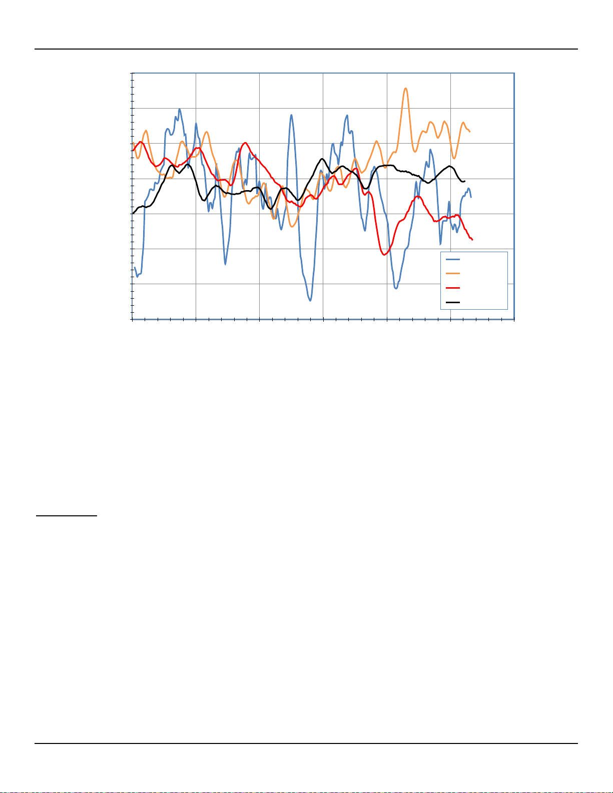
ST80/ST80L Flow Meter OPERATION
63.600
63.800
64.000
64.200
64.400
64.600
64.800
65.000
0 50 100 150 200 250 300
mA Output Converted to SFPS
Data Logger Samples (Every 250 mS or 240/Minute)
Damping = 0.25
Damping = 1.00
Damping = 3.00
Damping = 5.00
C01406-1-1
NAMUR Setup
Figure 41 – Chart: Flow Output Over Time with Various Flow Damping Values
Flow Input Moving Average (Boxcar) Filter
Use the Flow Input Moving Average Filter field to smooth out the input flow signal using a moving average (boxcar) filter. The boxcar filter
X
averages the last
number of readings. A larger boxcar value does a better job of averaging at the expense of a slower response time.
The factory default boxcar value is 8 (readings). With readings occurring at 5 times a second, the factory boxcar setting is an average of
the last 1.6 seconds.
Caution: High boxcar values result in reduced flow response time. Make sure that alarm conditions are not affected when
using the moving average filter.
NAMUR NE43 is a German fault detection standard that lets the user know if there is a fault within the instrument by forcing the 4-20 mA
output current outside the normal operating range of the instrument.
Figure 42 – NAMUR Fault
Fluid Components International LLC 41
Use the ST80/ST80L configuration software to enable/configure the NAMUR feature. The optional front panel HMI interface cannot access
NAMUR.
Click USB Connect on the home screen. Select the Configuration branch from the menu tree on the window's left side. Select the 4-20mA
User tab. Tick the desired channel’s NAMUR Enabled checkbox.
Page 50

OPERATION ST80/ST80L Fl o w Meter
Fault Bit
Fatal Fault Error or Status Description
1
CORE: any of these errors: I2C error, UART error, Mutex error, or Watchdog Reset.
4
CORE: unable to update process data (PD_NO_FE_DATA). Unable to get/use data from any active FEs.
6
CORE: detects FRAM/SPI error.
11
(Any) FE Board Temperature Out of Limits
14
CORE: unable to communicate with one or more FEs (PD_COMM_ERROR).
20
CORE: averaged temperature above “Temperature Max.”
21
CORE: averaged temperature above “Temperature Min.”
22
(Any) FE reports SENSOR_HEATER_SHORTED_FAULT.
24
(Any) FE reports SENSOR_HEATER_OPEN_FAULT.
27
(Any) FE reports SENSOR_ ADC_BELOW_ MIN_FAULT.
30
(Any) FE reports SENSOR_ ABOVE_ MAX_TEMPERATURE_FAULT.
31
(Any) FE reports SENSOR_ UNDER_ MIN_TEMPERATURE_FAULT.
Note: The NAMUR settings field in the 4-20 mA User tab will only show when the output is set for Flow or HART Flow. If
Temperature output is selected the NAMUR settings will not show up. NAMUR only works on Flow outputs.
field,
In the window's NAMUR
Send to Device to save the settings to the instrument. To discard changes just exit the screen (do not click Send to Device).
define the NAMUR output level by clicking either Set NAMUR @ 3.6 mA or Set NAMUR @ 21.0 mA. Click
Figure 43 – NAMUR Output Level Selection (4-20 mA User Tab)
When NAMUR is enabled, and a fatal fault is detected, the 4-20 mA output is forced to the preselected NAMUR output level. Use the Click
to Test NAMUR button (forces NAMUR output) as needed to verify the system setup and wiring.
Table 8 – Fatal Faults that Trigger NAMUR
42 Fluid Components International LLC
Page 51

ST80/ST80L Flow Meter OPERATION
Note:
Internal Delta-R Resistor (idR) Check
The Internal Delta-R Resistor (idR) Check is a routine designed to assess the ST80/ST80L internal normalization. The normalization process fine
tunes the instrument’s ability to accurately measure resistance. Proper normalization also allows FCI electronics to be interchangeable for
replacements, spares or repaired boards. If the unit’s normalization shifts, the accuracy of the meter may be compromised.
By passing the same sensor excitation current used to power the RTDs across three high precision idR resistors (60 Ω, 100 Ω, and 150 Ω) trendng
patterns can be established. Periodically run the idR check to verify proper operation of the ST80/ST80L electronics. Use the idR check as a
troubleshooting tool to isolate a fault between the sensor and the electronics.
Running the idR Check Using the Optional HMI
Hold the “Hot Key” (top sensor) for three seconds. Select Diagnostics and then Self T est . Select FE 1 IDR and enter the User Level Password
(E#C). After successful password entry the display shows the FE 1 IDR list again. Select (again) the desired FE. Observe that Test in Progress
displays along with a timer counting down the seconds. See Figure 47, page 45 for the idR test display sequence.
When the idR check completes the expected and measured values for each idR resistor are shown on the HMI display as shown in the
example in Figure 44 below. The left part of the screen shows the expected (EXP'D) values. The right part of the screen shows the
measured (MEAS'D) values. If all three checks pass (“P” shown at the right of all lines), PASSED displays at the bottom. Should any one
of the three checks fail (“F” shown at rightmost part of a line), FAILED displays at the bottom. Data from an HMI-initiated idR check is not
saved; therefore, record the data by hand as required.
Figure 44 – Example idR Check Results Display
Running the idR Check Using the ST80/ST80L Configuration Software
Click USB Connect on the home screen. Select the Diagnostics branch from the menu tree on the window's left side. Select the idR
Scheduled Tests tab. See Figure 45 below. Select the “FE #” desired from the Selected FE drop-down list (only FE1 shows for
ST80/ST80L). Two settings that affect scheduled and on-demand idR tests are provided on this screen: FEx Internal Delta-R Pass Fail
Criteria, Maximum Allowed Error (default = 0.5 ohms) and FE1 Output Mode During Test, Mode (default = Freeze Flow During Test).
Make changes to the default settings as required for your application.
In the FE1 Schedule Internal Resistor Check field, use the Mode drop-down list to select a schedule mode: Disabled (default), Day of Month
(1-28), Day of Week (0=Sun), or Every(Day). Use the Day, #days, DOW spinner control to define the selected schedule mode. Use the Time
spinner control to enter the desired scheduled check start time. Alternatively, click Run test now on FE1 to run the idR check on demand
(enter User level code 2772).
When an idR check is started from the configuration software (scheduled or on-demand) the displays shows the Fault
icon ( ) above the flow rate as the check runs. The Fault icon disappears when the idR check completes.
After clicking Run test now on FE1 the FE1 idR Test Results field displays the expected and the measured resistance values. These
instant checks are not logged to onboard memory (FRAM) and not displayed under the idR Test Logs tab as the Scheduled Tests files.
Fluid Components International LLC 43
Page 52

OPERATION ST80/ST80L Fl o w Meter
Figure 45 – Example Internal Delta R Scheduled Screen (After Clicking "Run test now...")
The result for a scheduled idR check is logged in FRAM. Click Get Test Log from Device in the idRTest Logs tab to view the idR test log
as shown in the example in Figure 46 below.
Figure 46 – Example Internal Delta R Test Logs Screen
44 Fluid Components International LLC
Page 53

ST80/ST80L Flow Meter OPERATION
HOT KEY
1. Normal Operation Display:
seconds.
2. Select Diagnostics.
3. Select Self Test.
4. Select FE1 IDR (FE 2 applicable
5. Input Password E#C.
6. Select (Enter) Password.
7. Select FE1 IDR again.
8. Observe idR test in progress
9. idR Test is Complete. Record
Select and hold the hot key for 3
to ST100A Series only).
Figure 47 – Internal Delta-R Resistor Check (idR) HMI Display Sequence
(seconds countdown).
values for comparison.
Fluid Components International LLC 45
Page 54
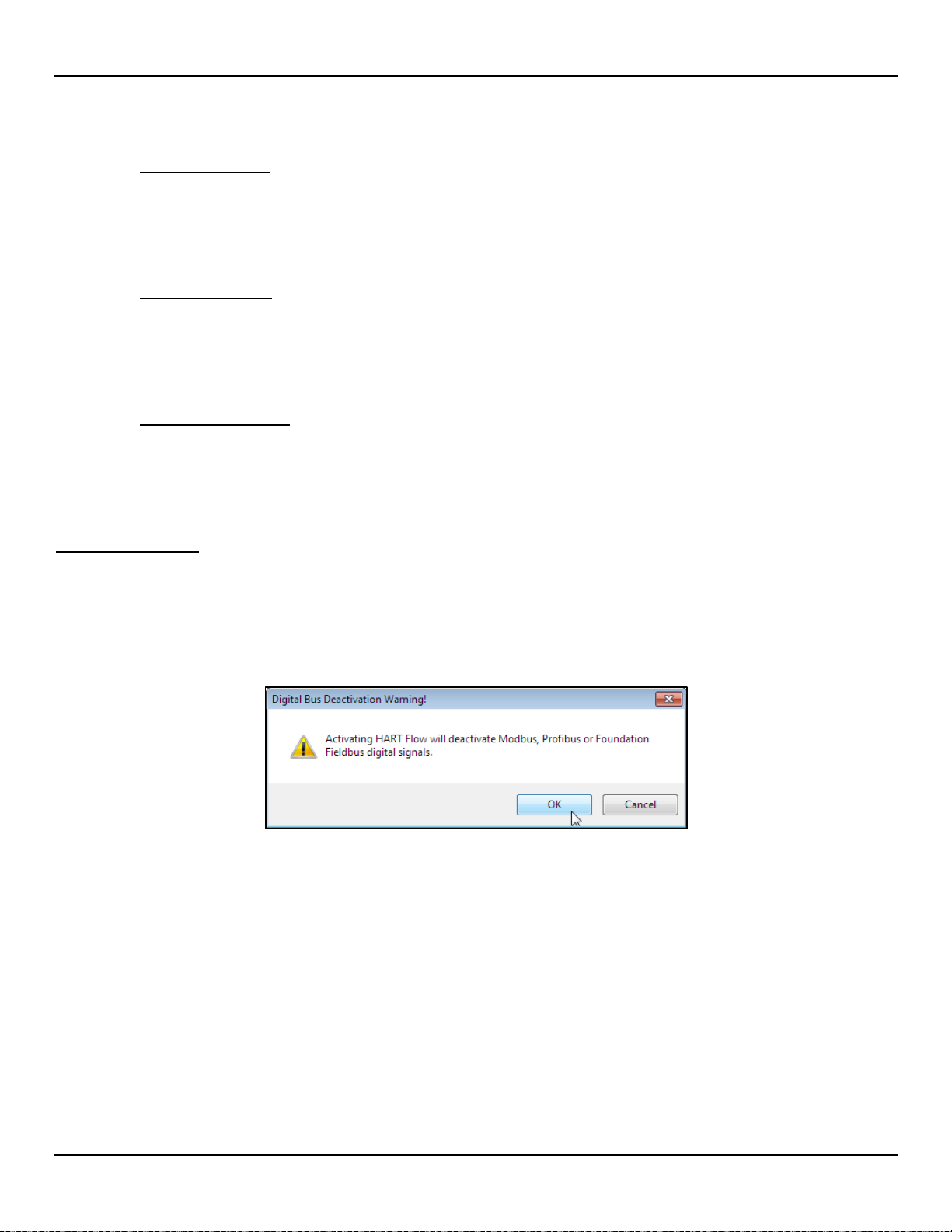
OPERATION ST80/ST80L Fl o w Meter
Analog Output Response to idR Check
During the idR sequence the analog outputs respond as listed below. Readings are taken with a 250 Ω load across Analog Output 1, 2 or 3.
NAMUR Enabled LOW
2.325 Vdc = 23.16 sfps = baseline (example: actual flow output varies from 1-5 volts)
0.900 Vdc = idR In Progress
1.000 Vdc = momentary state
2.326 Vdc = after 3 seconds. idR values are displayed now.
NAMUR Enabled HIGH
2.325 Vdc = 23.16 sfps = baseline (example: actual flow output varies from 1-5 volts)
5.250 Vdc = idR In Progress
1.000 Vdc = momentary state
2.326 Vdc = after 3 seconds. idR values are displayed now.
NAMUR Enabled Disabled
2.325 Vdc = 23.16 sfps = baseline (example: actual flow output varies from 1-5 volts)
1.000 Vdc = idR In Progress
2.326 Vdc = after 3 seconds. idR values are displayed now.
Using Digital Outputs
Digital busses (includes HART, Modbus, and FOUNDATION Fieldbus/PROFIBUS) are mutually exclusive, meaning only one can be active at
a time. When a particular digital output is specified at order time the unit is configured appropriately at the factory. Use the ST80/ST80L
configuration software (Configuration/Output) to change the digital output selection. Refer to the ST80/ST80L Configuration Software
manual 06EN003491 for details. Note that enabling a digital bus will deactivate the other digital bus currently in effect. Figure 48 below
shows the configuration software dialog box that appears when the user assigns 4-20 mA #1 to HART Flow with another digital bus
already active.
FOUNDATION Fieldbus/PROFIBUS operation requires the optional Fieldbus/PROFIBUS add-on card installed on the main board. Refer to
OUNDATION Fieldbus manual (06EN003492) and PROFIBUS manual (06EN003493 or 06EN003494) for operation details on these
the F
digital outputs.
Figure 48 – Digital Bus Deactivation Warning When Enabling HART
46 Fluid Components International LLC
Page 55

ST80/ST80L Flow Meter OPERATION
HART Variable Code
Device Variable
0
Volumetric Flow1
Primary Variable
0
66
1
Volume (Totalizer)
Secondary Variable
1
68
2
Mass Flow1
Primary Variable
2
72
3
Mass (Totalizer)
Secondary Variable
3
71
4
Velocity Flow1
Primary Variable
4
67
5
Temperature
Tertiary Variable
5
64
HART Operation
HART (Highway Addressable Remote Transducer) is a communication protocol that superimposes a low level digital data signal on a 4-20 mA
current loop. The primary function of the instrument’s HART interface is to present process data via process data commands 1, 3 and 9. Use the
configuration software (Configuration/Output) to set the instrument to HART mode by assigning 4-20 mA #1 to HART FLOW. Refer to the
ST80/ST80L Configuration Software manual 06EN003491 for details.
The ST80/ST80L does not implement the HART Burst mode. A HART master that supports HART 7.0 and higher is required. If using a
HART communicator, a unit that supports HART 7.0 or higher is required (i.e. Emerson 475 Communicator). Connect the installation
(factory/plant) HART wiring to the instrument as described in HART Connections, page 25.
Process Data Operation
The ST80/ST80L implements HART 7.0 while maintaining compatibility with earlier versions of the HART protocol. However, HART
commands 1 and 3 have been simplified to only report the primary variable Flow. Use command 9 to access the full suite of available
dynamic variables including temperature, totalizer, and others.
ST80/ST80L HART Process Data Organization
This section describes how the instrument process data is organized under the HART command 9. For details on command 9 see the
HART Specification “Universal Commands Specification” HCF_SPEC-127, Revision 7.1 and the command 9 description on page 54.
ST80/ST80L Process Variable Slots
Table 9 below lists the instrument’s 6 process variables that are read by HART command 9, with each process variable assigned a slot number.
Not all the variables described in this section are available in all configurations of the flow meter. For example, the Flow Totalizer may be
turned on or off.
The process variables include 3 flow classes or types of which only one class of flow is active at a time.
Table 9 – ST80/ST80L HART Process Variables
Slot # Process Variable
Note: 1. Only one active at a time.
Primary Variable Classifications
The instrument can provide flow data in unit types that span several HART classifications. Commands 50 and 51 are used to read and set,
respectively, which flow variable will be mapped to the primary variable. The PV device variable classification can only be one of the following:
● 0: Volumetric Flow
● 2: Mass Flow
● 4: Velocity Flow
Since only PV is used in this manner, command 50 returns 250 for SV, TV, and QV. The setting of the device variable classification determines
which class of flow-related variables is valid, and therefore displayed as implemented when variable slots are read by command 9.
Description
Device Variable Code
Classification
Device Description Files
A Device Description (DD) file lets the HART handheld or host software application fully configure any HART device for which it has a DD
installed. The ST80/ST80L DD files are available for download (pending) from the FieldComm Group website:
https://fieldcommgroup.org/registered-products/
Search by Manufacturer (Fluid Components International LLC) to find the instrument’s files under the product name: FCI ST80/ST100A
Series. The posted DD files are contained in a zip archive with FCI’s manufacturer ID and product device type hex values embedded in the
filename (e.g., hart.0000a6.a677.zip).
Fluid Components International LLC 47
Page 56
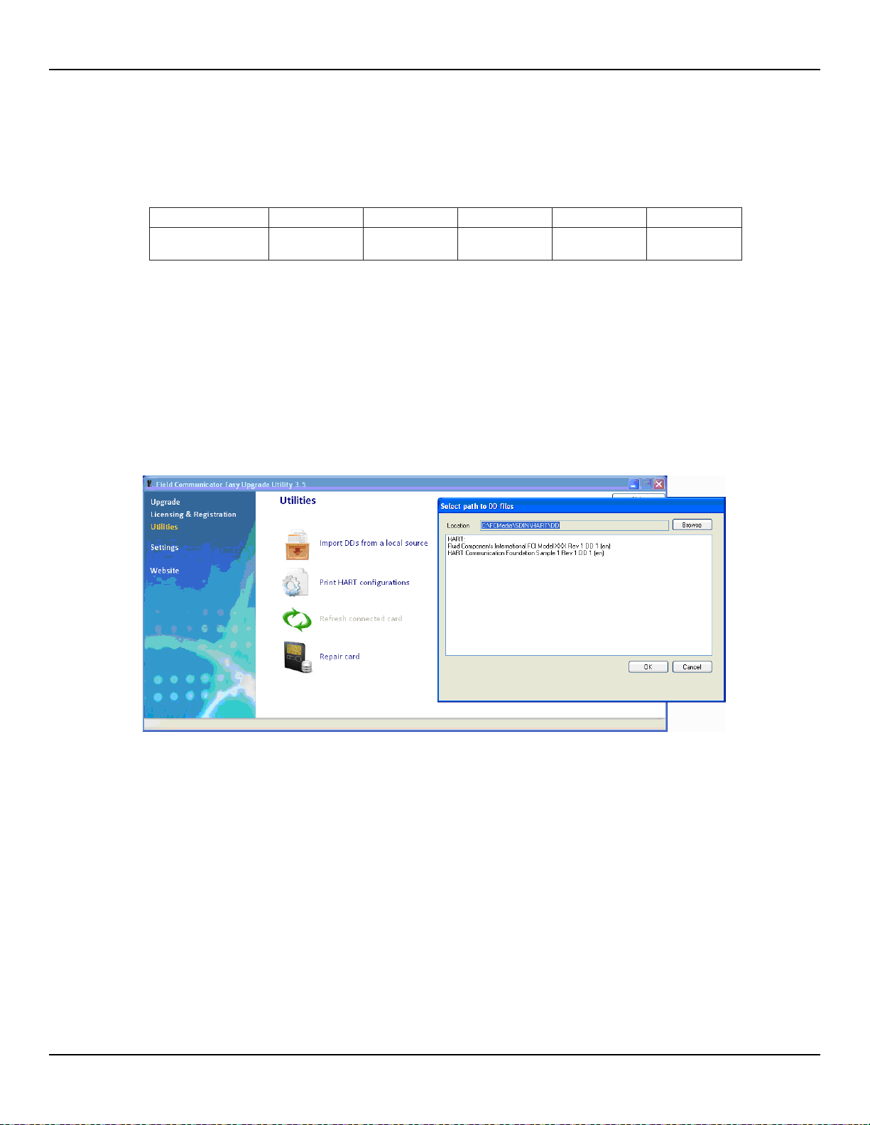
OPERATION ST80/ST80L Fl o w Meter
Note:
The ST80/ST80L and the ST100A Series are in the same product family.
Product Name
Product Type
HART Version
Mfgr. ID
Device Type
Dev. Revision
FCI ST80/ST100A
Series
Note:
The ST80/ST80L uses the same DD files as the ST100A Series. The handheld communicator screens will, therefore,
Table 10 below summarizes the instrument’s FieldComm Group device registration information.
Table 10 – ST80/ST80L HART Field Device Registration Information
Flow 7 0x00A6 0xA677 01
EDDL Files
The ST80/ST80L EDDL (Electronic Device Description Language) files are support files that provide an extended description of each
object in the Virtual Field Device (VFD), and provide information needed for a control system or host to understand the meaning of the data
in the VFD including the human interface. The EDDL file can be thought as a “driver” for the device.
Loading the DD Files to the 475 Field Communicator
Use the “Easy Upgrade Utility” from EMERSON to load the DDPs into the Field Communicator. Below is the procedure for how to load DD
files into the 475-Field communicator.
Open the Field Communicator Easy Upgrade Utility program and click Utilities on the left hand menu. Select Import DDs from a local
source. Then select the FCI files from the resulting List dialog and click on OK. See Figure 49 below.
Figure 49 – Field Communicator Easy Upgrade Utility, Import DD
Service Data Operation
Shown below is example service information as provided by the Emerson 475 HART communicator with FCI’s DD files loaded. The same
information seen by the 475 is shown in the DCS (Distributed Control System) when the ST80/ST80L HART DD files are loaded. The
screens shown below are a subset of the total 475 HART communicator information for the ST80/ST80L.
show both ST80 and ST100A. ST100A-specific differences are noted in the text below.
48 Fluid Components International LLC
Page 57

ST80/ST80L Flow Meter OPERATION
Root Menu
Shown below i s the Root Menu as displayed on the Emerson 475 HART
communicator.
Device Setup (from Root Menu)
The Device Setup function is a gateway to ST80/ST80L device i nformation,
process data and setup, both basic and advanced. Additional o ptions include K
Factor displ ay/adjust, totalizer reset, and customer flow limits.
Basic Setup (from Device Setup)
The Basic Set up function includes the ability to review and ch ange the
engineering units of the process variables, review and change the plenum or pipe
size, enable or disable the Totalizer, review and change devi ce information, reset
the operation of the ST80/ST80L to th e factory settings, enabl e or disable the
write protec t, and PV Setup.
Process Data Example (from Device Setup)
The Process Data screen lets you revi ew process dat a including flow rate, temperature,
pressure, and the process variable’ s 4-20 mA current loop output value.
Process Data Time Example (from Device Setup)
The Process Data Time screen lets you revi ew the curr ent process variabl e value and
its engineering units, device st atus, and the current date and time (24-hour clock).
Fluid Components International LLC 49
Page 58

OPERATION ST80/ST80L Fl o w Meter
Engineering Units Example (from Basic Setup)
Factory Reset (from Basic Setup)
CAUTION – Th e Fact or y Res et com mand r el oads t he c on fi gurat i on and cal ibr ati on
parameters that were l oade d int o the i ns tr ument dur ing t h e ori ginal cal i brat ion and
setup. Any subseque nt changes ma de t o th e c ali brat i on paramet ers c onf igur ati on
will be lost when the Fac t ory Res et com mand i s exec ut ed.
Device Configuration (from Advance Setup Device Setup)
Use the device configuration functi on to view/set up the flow m eter’s 4-20 mA
current output channels. Raw DA counts are shown for 4 mA and 20 mA and the
output variable is shown as OFF, Flow, Temperature, or Pressure*.
*NOTE – Channel 3 setup and the pressure variabl e selection apply to ST10 0A
Series only.
Device Status (from Device Setup)
Use the device status function to see the hex values of the Command 48
Additional Device Status (6-byte fiel d, bytes 0-5). The topmost “Device status”
shows the value of the “More Status Available” bit within the HART command
response data field (b4 in 2
subsequent error(s) shown in the Addit ional Device Status bytes (Command 48).
If b4 is cleared, there is no additional status to report. Refer t o Co mm a nd 48,
Additional Device Status Bytes, page 68.
nd
byte). If b4 is set, more status is available and the
50 Fluid Components International LLC
Page 59

ST80/ST80L Flow Meter OPERATION
Device Factory Calibration Example (from Advance Setup
Device Setup)
The Device Fac tory Calibration funct ion lets you review the li m its that have been
set for the Fl ow, Temperature, and Pressure* process parameters.
*NOTE – Pressure limits apply to ST100A Series only.
Fluid Components International LLC 51
Page 60
OPERATION ST80/ST80L Fl o w Meter
Command 0: Read Unique Identifier
Byte
Format
Description
Request Data Bytes
None
Response Data Bytes
0
Unsigned-8
254
1–2
Enum
Expanded Device Type
3 Unsigned-8
Minimum number of preambles from master to slave
4 Unsigned-8
HART Protocol Revision Number: 7
5 Unsigned-8
Device Revision Number
6 Unsigned-8
Software Revision Number
7 Unsigned-5
(Most Significant 5 Bits) Hardware Revision Level
7 Enum
Physical Signaling Code: 00 = Bell 202 Current (4-20 mA)
8 Bits
Flags: (Unused)
9–11
Unsigned-24
Device ID
12
Unsigned-8
Minimum number of preambles from the slave to master
13
Unsigned-8
Maximum Number of Device Variables
14–15
Unsigned-16
Configuration Change Counter
16
Bits
Extended Field Device Status
17–18
Enum
Manufacturer ID Code: 166
DEC
/00A6
HEX
(FCI)
19–20
Enum
Private Label Distributor Code
21
Enum
Device Profile = 1 “HART Process Automation Device”
Response Codes
See Table 16, page 67, for response code list.
Command 1: Read Primary Variable (Flow Units, & Flow Value)
Byte
Format
Description
Request Data Bytes
None
Response Data Bytes
0
Enum
Primary Variable Units Code
1–4
Float
Primary Variable Value
Response Codes
See Table 16, page 67, for response code list.
HART Command List Reference
The HART commands are divided into three classes.
● Universal Commands
● Common Practice Commands
● Device Specific Commands
Barring no communication error, a field or slave device returns a response code as part of the 2-byte status response to a command. Refer
to Command Status Bytes on page 66. The ST80/ST80L response codes listed in the following command summaries are a subset of the
response codes listed in the HART specification.
ST80/ST80L HART Universal Commands
The ST80/ST80L HART supports Universal Commands 0 through 22 and 38 and 48. Commands 4 and 5 are reserved under Universal
Command Specification Rev. 7.1 (HCF_SPEC-127, Revision 7.1) and not implemented in this specification. There is no HART command
10. Table 11 below summarizes the instrument’s HART Universal command set and the data associated with each command.
Table 11 – HART Universal Commands
52 Fluid Components International LLC
Page 61
ST80/ST80L Flow Meter OPERATION
Command 2: Read Primary Variable Loop Current and Percent of Range
Byte
Format
Description
Request Data Bytes
None
Response Data Bytes
0–3
Float
Primary Variable Loop Current (mA)
4–7
Float
Primary Variable Percent of Range (%)
Response Codes
See Table 16, page 67, for response code list.
Command 3: Read Dynamic Variable (Flow) and Loop Current
Byte
Format
Description
Request Data Bytes
None
Response Data Bytes
0–3
Float
PV Loop Current: 4-20 mA
4 Enum
PV HART Unit Code, Flow
5–8
Float
PV Flow Value
Response Codes
See Table 16, page 67, for response code list.
Command 6: Write Polling Address
Byte
Format
Description
Request Data Bytes
0
Unsigned-8
Polling Address of Device
1 Enum
Loop Current Mode
Response Data Bytes
0
Unsigned-8
Polling Address of Device
1 Enum
Loop Current Mode
Response Codes
See Table 16 for response code list.
Command 7: Read Loop Configuration
Byte
Format
Description
Request Data Bytes
None
Response Data Bytes
0
Unsigned-8
Polling Address of Device
1 Enum
Loop Current Mode
Response Codes
See Table 16, page 67, for response code list.
Command 8: Read Dynamic Variable Classifications
Byte
Format
Description
Request Data Bytes
None
Response Data Bytes
0
Unsigned-8
Primary Variable Classification
1-3
Unsigned-8
SV, TV and QV not used ( Classification 0)
Response Codes
See Table 16, page 67, for response code list.
Fluid Components International LLC 53
Page 62

OPERATION ST80/ST80L Fl o w Meter
Command 9: Read Device Variables with Status1
Byte
Format
Description
Request Data Bytes
0
Unsigned-8
Slot 0: Device Variable Code
1 Unsigned-8
Slot 1: Device Variable Code
2 Unsigned-8
Slot 2: Device Variable Code
3 Unsigned-8
Slot 3: Device Variable Code
4 Unsigned-8
Slot 4: Device Variable Code
5 Unsigned-8
Slot 5: Device Variable Code
6 Unsigned-8
Slot 6: Device Variable Code
7 Unsigned-8
Slot 7: Device Variable Code
Response Data Bytes
0
Bits
Extended Field Device Status
1 Unsigned-8
Slot 0: Device Variable Code
2 Enum
Slot 0: Device Variable Classification
3 Enum
Slot 0: Units Code
4–7
Float
Slot 0: Device Variable Value
8 Bits
Slot 0: Device Variable Status
9 Unsigned-8
Slot 1: Device Variable Code
10
Enum
Slot 1: Device Variable Classification
11
Enum
Slot 1: Units Code
12–15
Float
Slot 1: Device Variable Value
16
Bits
Slot 1: Device Variable Status
17
Unsigned-8
Slot 2: Device Variable Code
18
Enum
Slot 2: Device Variable Classification
19
Enum
Slot 2: Units Code
20–23
Float
Slot 2: Device Variable Value
24
Bits
Slot 2: Device Variable Status
25
Unsigned-8
Slot 3: Device Variable Code
26
Enum
Slot 3: Device Variable Classification
27
Enum
Slot 3: Units Code
28–31
Float
Slot 3: Device Variable Value
32
Bits
Slot 3: Device Variable Status
33
Unsigned-8
Slot 4: Device Variable Code
34
Enum
Slot 4: Device Variable Classification
35
Enum
Slot 4: Units Code
36–39
Float
Slot 4: Device Variable Value
40
Bits
Slot 4: Device Variable Status
41
Unsigned-8
Slot 5: Device Variable Code
42
Enum
Slot 5: Device Variable Classification
43
Enum
Slot 5: Units Code
44–47
Float
Slot 5: Device Variable Value
48
Bits
Slot 5: Device Variable Status
49
Unsigned-8
Slot 6: Device Variable Code
50
Enum
Slot 6: Device Variable Classification
51
Enum
Slot 6: Units Code
52–55
Float
Slot 6: Device Variable Value
56
Bits
Slot 6: Device Variable Status
57
Unsigned-8
Slot 7: Device Variable Code
58
Enum
Slot 7: Device Variable Classification
59
Enum
Slot 7: Units Code
60–63
Float
Slot 7: Device Variable Value
64
Bits
Slot 7: Device Variable Status
65–68
Time
Slot 0: Data Time Stamp
Response Codes
See Table 16, page 67, for response code list.
Note: 1. Command 9 takes in a variable list of parameters and similarly returns a variable length response.
54 Fluid Components International LLC
Page 63
ST80/ST80L Flow Meter OPERATION
Command 11: Read Unique Identifier Associated with Tag
Byte
Format
Description
Request Data Bytes
0–5
Packed
Tag, Packed ASCII
Response Data Bytes
0
Unsigned-8
254 1–2
Enum
Expanded Device Type
3 Unsigned-8
Minimum number of preambles from master to slave
4 Unsigned-8
HART Protocol Revision Number: 7
5 Unsigned-8
Device Revision Number
6 Unsigned-8
Software Revision Number
7 Unsigned-5
(Most Significant 5 Bits) Hardware Revision Level: 1
7 Enum
Physical Signaling Code: 00 = Bell 202 Current (4-20 mA)
8 Bits
Flags: (Unused)
9–11
Unsigned-24
Device ID
12
Unsigned-8
Minimum number of preambles from the slave to master
13
Unsigned-8
Maximum Number of Device Variables
14–15
Unsigned-16
Configuration Change Counter
16
Bits
Extended Field Device Status
17–18
Enum
Manufacturer ID Code: 166
DEC
/00A6
HEX
(FCI)
19–20
Enum
Private Label Distributor Code
21
Enum
Device Profile = 1 “HART Process Automation Device”
Response Codes
See Table 16, page 67, for response code list.
Command 12: Read Message Contained Within Device
Byte
Format
Description
Request Data Bytes
None
Response Data Bytes
0–23
Bitstring
24-character message string
Response Codes
See Table 16, page 67, for response code list.
Command 13: Read Tag, Descriptor, Date
Byte
Format
Description
Request Data Bytes
None
Response Data Bytes
0–5
Packed
Tag 6–17
Packed
Descriptor
18–20
Date
Date Code: Day, Month, Year (YR = setting year minus 1900)
Response Codes
See Table 16, page 67, for response code list.
Command 14: Read Primary Variable (Flow) Transducer Information
Byte
Format
Description
Request Data Bytes
None
Response Data Bytes
0–2
Unsigned-24
Transducer Serial Number
3 Enum
Transducer Units Code
4–7
Float
Upper Transducer Limit
8–11
Float
Lower Transducer Limit
12–15
Float
Minimum Span
Response Codes
See Table 16, page 67, for response code list.
Fluid Components International LLC 55
Page 64
OPERATION ST80/ST80L Fl o w Meter
Command 15: Read Device Information
Byte
Format
Description
Request Data Bytes
None
Response Data Bytes
0
Enum
Flow Alarm Selection Code
1 Enum
Flow Transfer Function Code (not supported)
2 Enum
Flow Upper and Lower Range Value Units Code
3–6
Float
Flow Upper Range Value
7–10
Float
Flow Lower Range Value
11–14
Float
Flow Damping Value
15
Enum
Write Protect Code
16
Enum
Reserved
17
Bits
Flow Analog Channel Flags (not supported)
Response Codes
See Table 16, page 67, for response code list.
Command 16: Read Final Assembly Number
Byte
Format
Description
Request Data Bytes
None
Response Data Bytes
0–2
Unsigned-24
STAK ELECT ASSY #
Response Codes
See Table 16, page 67, for response code list.
Command 17: Write Message Into Device
Byte
Format
Description
Request Data Bytes
0–23
Packed
Message String Used by Master
Response Data Bytes1
0–23
Packed
Message String
Response Codes
See Table 16, page 67, for response code list.
Command 18: Write Tag, Descriptor, Date
Byte
Format
Description
Request Data Bytes
0–5
Packed
Tag
6–17
Packed
Descriptor Used by Master
18–20
Date
Date Code Used by Master
Response Data Bytes1
0–5
Packed
Tag 6–17
Packed
Descriptor
18–20
Date
Date Code: Day, Month, Year (YR = setting year minus 1900)
Response Codes
See Table 16, page 67, for response code list.
Command 19: Write Final Assembly Number
Byte
Format
Description
Request Data Bytes
0–2
Unsigned-24
STAK ELECT ASSY #
Response Data Bytes1
0–2
Unsigned-24
STAK ELECT ASSY #
Response Codes
See Table 16, page 67, for response code list.
Note: 1. The value returned in the response data bytes reflects the value actually used by the field device.
Note: 1. The value returned in the response data bytes reflects the value actually used by the field device.
Note: 1. The value returned in the response data bytes reflects the value actually used by the field device.
56 Fluid Components International LLC
Page 65
ST80/ST80L Flow Meter OPERATION
Command 20: Read Long Tag
Byte
Format
Description
Request Data Bytes
None
Response Data Bytes
0–31
Latin-1
Long Tag
Response Codes
See Table 16, page 67, for response code list.
Command 21: Read Unique Identifier Associated with Long Tag
Byte
Format
Description
Request Data Bytes
0–31
Latin-1
Long Tag
Response Data Bytes
0
Unsigned-8
254
1–2
Enum
Expanded Device Type
3 Unsigned-8
Minimum Number Of Preambles From Master to Slave
4 Unsigned-8
HART Protocol Revision Number: 7
5 Unsigned-8
Device Revision Number
6 Unsigned-8
Software Revision Number
7 Unsigned-5
(Most Significant 5 Bits) Hardware Revision Level: 1
7 Enum
Physical Signaling Code: 00 = Bell 202 Current (4-20 mA)
8 Bits
Flags: (Unused)
9–11
Unsigned-24
Device ID
12
Unsigned-8
Minimum Number Of Preambles From Slave to Master
13
Unsigned-8
Maximum Number of Device Variables
14–15
Unsigned-16
Configuration Change Counter
16
Bits
Extended Field Device Status
17–18
Enum
Manufacturer ID Code: 166
DEC
/00A6
HEX
(FCI)
19–20
Enum
Private Label Distributor Code
21
Enum
Device Profile = 1 “HART Process Automation Device”
Response Codes
See Table 16, page 67, for response code list.
Command 22: Write Long Tag
Byte
Format
Description
Request Data Bytes
0–31
Latin-1
Long Tag
Response Data Bytes
0–31
Latin-1
Long Tag
Response Codes
See Table 16, page 67, for response code list.
Command 38: Reset Configuration Changed Flag
Byte
Format
Description
Request Data Bytes
0–1
Unsigned-16
Configuration Change Counter
Response Data Bytes
0–1
Unsigned-16
Configuration Change Counter
Response Codes
See Table 16, page 67, for response code list.
Fluid Components International LLC 57
Page 66
OPERATION ST80/ST80L Fl o w Meter
Command 48: Read Additional Device Status
Byte
Format
Description
Request Data Bytes
0–5
Bits
Device-Specific Status (only first 6 bytes used, see page 68 for
additional info)
6 Bits
Extended Device Status. Normally “0”; set to “1” (0x01) if
maintenance is required.
7 Bits
Device Operating Mode (not used, bit cleared to 0)
8 Bits
Standardized Status 0 (not used, bit cleared to 0)
9 Bits
Standardized Status 1 (not used, bit cleared to 0)
10
Bits
Analog Channel Saturated (not used, bit cleared to 0)
11
Bits
Standardized Status 2 (not used, bit cleared to 0)
12
Bits
Standardized Status 3 (not used, bit cleared to 0)
13
Bits
Analog Channel Fixed
14–24
Bits
Device-Specific Status2 (not used, bit cleared to 0)
Response Data Bytes
0–5
Bits
Device-Specific Status (only first 6 bytes used, see page 68)
6 Bits
Extended Device Status. Normally “0”; set to “1” (0x01) if
maintenance is required.
7 Bits
Device Operating Mode (not used, bit cleared to 0)
8 Bits
Standardized Status 0 (not used, bit cleared to 0)
9 Bits
Standardized Status 1 (not used, bit cleared to 0)
10
Bits
Analog Channel Saturated (not used, bit cleared to 0)
11
Bits
Standardized Status 2 (not used, bit cleared to 0)
12
Bits
Standardized Status 3 (not used, bit cleared to 0)
13
Bits
Analog Channel Fixed
14–24
Bits
Device-Specific Status2 (not used, bit cleared to 0)
Response Codes
See Table 16, page 67, for response code list.
58 Fluid Components International LLC
Page 67
ST80/ST80L Flow Meter OPERATION
Command 35: Write Primary Variable (PV) Range Values
Byte
Format
Description
Request Data Bytes
0
Unsigned-8
PV Upper and Lower Range Values Units Code
1–4
Float
PV Upper Range Value (Customer Max. Flow Limit)
5–8
Float
PV Lower Range Value (Customer Min. Flow Limit)
Response Data Bytes1
0
Unsigned-8
PV Upper and Lower Range Values Units Code
1–4
Float
PV Upper Range Value
5–8
Float
PV Lower Range Value
Response Codes
See Table 16, page 67, for response code list.
Command 40: Enter/Exit Fixed Current Mode
Byte
Format
Description
Request Data Bytes1
0–3
Float
PV Fixed Current Level (mA units); “0” to Exit Fixed Current
Response Data Bytes
0–3
Float
Actual PV Current Level
Response Codes
See Table 16, page 67, for response code list.
Command 42: Perform Device Reset (Soft Reset of Flow Meter)1
Byte
Format
Description
Request Data Bytes
None
Response Data Bytes
None
Response Codes
See Table 16, page 67, for response code list.
Command 44: Write Primary Variable Units
Byte
Format
Description
Request Data Bytes
0
Enum
PV Units Code
Response Data Bytes1
0
Enum
PV Units Code
Response Codes
See Table 16, page 67, for response code list.
Command 45: Trim DAC Zero – Measured Current Chan #1 (in mA)
Byte
Format
Description
Request Data Bytes
0–3
Float
Ext. Measured Current Ch. #1 Level (4 mA Zero_DAC)
Response Data Bytes1
0–3
Float
Actual Measured Current Ch. #1 Level (4 mA Zero_DAC)
Response Codes
See Table 16, page 67, for response code list.
ST80/ST80L HART Common Practice Commands
The ST80/ST80L supports Common Practice commands 35, 40, 42, 44, 45, 46, 50 and 51. Table 12 below summarizes the instrument’s
HART Common Practice command set and the data associated with each command.
Table 12 – HART Common Practice Commands
Note: 1. The value returned in the response data bytes reflects the rounded or truncated value actually used by the device.
Notes: 1. Specify a value (in mA) to drive Ch. 1 to a particular output value. Specify “0” to exit the fixed current mode.
Note: 1. Send Command 42 (no data) to reset the instrument. No response is returned due to reboot.
Note: 1. The value returned in the response data bytes reflects the value actually used by the device.
Note: 1. The value returned in the response data bytes reflects the rounded or truncated value actually used by the device.
Fluid Components International LLC 59
Page 68
OPERATION ST80/ST80L Fl o w Meter
Command 46: Trim DAC Gain – Measured Current Chan #1 (in mA)
Byte
Format
Description
Request Data Bytes
0–3
Float
Ext. Measured Current Ch. #1 Level (20 mA GainDAC)
Response Data Bytes1
0–3
Float
Actual Measured Current Ch. #1 Level (20 mA GainDAC)
Response Codes
See Table 16, page 67, for response code list.
Command 50: Read Dynamic Variable Assignments
Byte
Format
Description
Request Data Bytes
None
Response Data Bytes
0
Unsigned-8
Device Variable assigned to the primary variable.
1–3 — 250 (Unused)
Response Codes
See Table 16 for response code list.
Command 51: Write Dynamic Variable Assignments
Byte
Format
Description
Request Data Bytes
0
Unsigned-8
Device Variable assigned to the primary variable.
Response Data Bytes1
0
Unsigned-8
Device Variable assigned to the primary variable.
1–3 — 250 (Unused)
Response Codes
See Table 16 for response code list.
Note: 1. The value returned in the response data bytes reflects the rounded or truncated value actually used by the device.
Note: 1. The value returned in the response data bytes reflects the value actually used by the device.
60 Fluid Components International LLC
Page 69
ST80/ST80L Flow Meter OPERATION
Group No.
Description
Command Numbers
Group 1
Commands to set up and configure the instrument.
137, 138, 139, 140, 145, 146,
148, 149, 150, 159
Group 2
Commands to set up 4–20 mA output channels including the OUTZ, and
OUTF parameters.
160, 161, 163, 164, 166, 167
Group 3
Commands to view individual FE process. The view is a snapshot of
sensor data at the time of the request; i.e., it does not update in real time.
170
Group 4
Commands to display the factory-set calibrated limit of the instrument for
flow, process temperature and pressure variables.
151, 154, 157
Group 5
Other Category – Commands outside the above listed groups.
159, 179, 180, 181, 182, 183,
193
Command 137: Read Totalizer And Rollover Values
Byte
Format
Description
Request Data Bytes
None
—
—
Response Data Bytes
0–3
Float
Totalizer
Response Codes
See Table 16, page 67, for response code list.
Command 138: Read Totalizer State
Byte
Format
Description
Request Data Bytes
None
— — Response Data Bytes
0
Unsigned-8
Totalizer State: 0 = OFF; 1 = ON
Response Codes
See Table 16, page 67, for response code list.
Command 139: Write Totalizer State
Byte
Format
Description
Request Data Bytes
0
Unsigned-8
Totalizer State: 0 = OFF; 1 = ON
Response Data Bytes
0
Unsigned-8
Totalizer State: 0 = OFF; 1 = ON
Response Codes
See Table 16, page 67, for response code list.
Command 140: Read Device Information
Byte
Format
Description
Request Data Bytes
None
—
—
Response Data Bytes
0–9
Bits
Device CO
10–19
Bits
Device Serial Number
20–23
Bits
Device Software Version
Response Codes
See Table 16, page 67, for response code list.
ST80/ST80L HART Device Specific Commands
The ST80/ST80L Manufacturer Specific or Device Specific commands start at command 137. Use the device specific commands to setup
and configure the ST80/ST80L instrument via HART. The ST80/ST80L device specific commands are grouped in functional categories as
summarized in Table 13 below.
Table 13 – ST80/ST80L HART Device Specific Command Groupings
184, 185,186, 187, 188, 191.
Table 14 below summarizes the instrument’s HART Device Specific command set and the data associated with each command.
Table 14 – HART Device Specific Commands
Fluid Components International LLC 61
Page 70
OPERATION ST80/ST80L Fl o w Meter
Command 145: Read Customer Engineering Units
Byte
Format
Description
Request Data Bytes
None
—
—
Response Data Bytes
0
Unsigned-8
Units Code for Flow
1 Unsigned-8
Units Code for Temperature
2 Unsigned-8
Units Code for Totalizer
3 Unsigned-8
Units Code for Pressure
Response Codes
See Table 16, page 67, for response code list.
Command 146: Write Customer Engineering Units
Byte
Format
Description
Request Data Bytes
0
Unsigned-8
Units Code for Flow
1 Unsigned-8
Units Code for Temperature
2 Unsigned-8
Units Code for Totalizer (must match Flow units)
3 Unsigned-8
Units Code for Pressure
Response Data Bytes
0
Unsigned-8
Units Code for Flow
1 Unsigned-8
Units Code for Temperature
2 Unsigned-8
Units Code for Totalizer
3 Unsigned-8
Units Code for Pressure
Response Codes
See Table 16, page 67, for response code list.
Command 148: Read Plenum Information (Pipe Size)
Byte
Format
Description
Request Data Bytes
None
—
—
Response Data Bytes
0–3
Float
Pipe Height Value
4–7
Float
Pipe Width (Diameter) Value
8 Unsigned-8
Plenum Units Code
Response Codes
See Table 16, page 67, for response code list.
Command 149: Write Plenum Information (Pipe Size)
Byte
Format
Description
Request Data Bytes
0–3
Float
Pipe Height Value
4–7
Float
Pipe Width (Diameter) Value
8 Unsigned-8
Plenum Units Code
Response Data Bytes
0-3
Float
Pipe Height Value
4–7
Float
Pipe Width (Diameter) Value
8 Unsigned-8
Plenum Units Code
Response Codes
See Table 16, page 67, for response code list.
Command 150: Write “Write Protect Mode”
Byte
Format
Description
Request Data Bytes
0
Unsigned-8
Write Protect Mode: 0x00 = Disable; 0x01 = Enable
Response Data Bytes
0
Unsigned-8
Write Protect Mode: 0x00 = Disable; 0x01 = Enable
Response Codes
See Table 16, page 67, for response code list.
62 Fluid Components International LLC
Page 71
ST80/ST80L Flow Meter OPERATION
Command 151: Read Calibration Flow Limits
Byte
Format
Description
Request Data Bytes
None
—
—
Response Data Bytes
0–3
Float
Flow Lower Limit Value
4–7
Float
Flow Upper Limit Value
Response Codes
See Table 16, page 67, for response code list.
Command 154: Read Calibration Temperature Limits
Byte
Format
Description
Request Data Bytes
None
—
—
Response Data Bytes
0–3
Float
Temperature Lower Limit Value
4–7
Float
Temperature Upper Limit Value
Response Codes
See Table 16, page 67, for response code list.
Command 157: Read Calibration Pressure Limits
Byte
Format
Description
Request Data Bytes
None
—
—
Response Data Bytes
0–3
Float
Pressure Lower Limit Value
4–7
Float
Pressure Upper Limit Value
Response Codes
See Table 16, page 67, for response code list.
Command 159: Write Factory Restore
Byte
Format
Description
Request Data Bytes1
None
—
None (no data)
Response Data Bytes
None
—
None (returns nothing)
Response Codes
See Table 16, page 67, for response code list.
Command 160: Write (4-20 mA) Output Channel #1 Parameters
Byte
Format
Description
Request Data Bytes
0–1
Unsigned-16
D/A Setting for 4 mA Out (OUTZ1)
2–3
Unsigned-16
D/A Setting for 4 mA Out (OUTF1)
4 Unsigned-8
Channel #1 Out Variable
Response Data Bytes
0–1
Unsigned-16
D/A Setting for 4 mA Out (OUTZ1)
2–3
Unsigned-16
D/A Setting for 4 mA Out (OUTF1)
4 Unsigned-8
Channel #1 Out Variable
Response Codes
See Table 16, page 67, for response code list.
Command 161: Read (4-20 mA) Output Channel #1 Parameters
Byte
Format
Description
Request Data Bytes
None
— — Response Data Bytes
0–1
Unsigned-16
D/A Setting for 4 mA Out (OUTZ1)
2–3
Unsigned-16
D/A Setting for 4 mA Out (OUTF1)
4 Unsigned-8
Channel #1 Out Variable
Response Codes
See Table 16, page 67, for response code list.
Note: 1. Send Command 159 with no data to reload the instrument’s factory default programming.
Fluid Components International LLC 63
Page 72
OPERATION ST80/ST80L Fl o w Meter
Command 163: Write (4-20 mA) Output Channel #2 Parameters
Byte
Format
Description
Request Data Bytes
0–1
Unsigned-16
D/A Setting for 4 mA Out (OUTZ2)
2–3
Unsigned-16
D/A Setting for 4 mA Out (OUTF2)
4 Unsigned-8
Channel #2 Out Variable
Response Data Bytes
0–1
Unsigned-16
D/A Setting for 4 mA Out (OUTZ2)
2–3
Unsigned-16
D/A Setting for 4 mA Out (OUTF2)
4 Unsigned-8
Channel #2 Out Variable
Response Codes
See Table 16, page 67, for response code list.
Command 164: Read (4-20 mA) Output Channel #2 Parameters
Byte
Format
Description
Request Data Bytes
None
— — Response Data Bytes
0–1
Unsigned-16
D/A Setting for 4 mA Out (OUTZ2)
2–3
Unsigned-16
D/A Setting for 4 mA Out (OUTF2)
4 Unsigned-8
Channel #2 Out Variable
Response Codes
See Table 16, page 67, for response code list.
Command 166: Write (4-20 mA) Output Channel #3 Parameters
Byte
Format
Description
Request Data Bytes
0–1
Unsigned-16
D/A Setting for 4 mA Out (OUTZ3)
2–3
Unsigned-16
D/A Setting for 4 mA Out (OUTF3)
4 Unsigned-8
Channel #3 Out Variable
Response Data Bytes
0–1
Unsigned-16
D/A Setting for 4 mA Out (OUTZ3)
2–3
Unsigned-16
D/A Setting for 4 mA Out (OUTF3)
4 Unsigned-8
Channel #3 Out Variable
Response Codes
See Table 16, page 67, for response code list.
Command 167: Read (4-20 mA) Output Channel #3 Parameters
Byte
Format
Description
Request Data Bytes
None
— — Response Data Bytes
0–1
Unsigned-16
D/A Setting for 4 mA Out (OUTZ3)
2–3
Unsigned-16
D/A Setting for 4 mA Out (OUTF3)
4 Unsigned-8
Channel #3 Out Variable
Response Codes
See Table 16, page 67, for response code list.
Command 170: Read Bank #1 Sensor Variables
Byte
Format
Description
Request Data Bytes
None
— — Response Data Bytes
0–3
Float
Flow Value Sensor #1
4–7
Float
Temperature Value Sensor #1
8–11
Float
Pressure Value Sensor #1
12–15
Float
Flow Value Sensor #2
16–19
Float
Temperature Value Sensor #2
20–23
Float
Pressure Value Sensor #2
24–27
Float
Flow Value Sensor #3
28–31
Float
Temperature Value Sensor #3
32–35
Float
Pressure Value Sensor #3
36–39
Float
Flow Value Sensor #4
40–43
Float
Temperature Value Sensor #4
44–47
Float
Pressure Value Sensor #4
Response Codes
See Table 16, page 67, for response code list.
64 Fluid Components International LLC
Page 73
ST80/ST80L Flow Meter OPERATION
Command 179: Write/Set Calibration Group
Byte
Format
Description
Request Data Bytes
0
Unsigned-8
Write/Set Calibration Group
Response Data Bytes
0
Unsigned-8
Write/Set Calibration Group
Response Codes
See Table 16, page 67, for response code list.
Command 180: Read Calibration Group
Byte
Format
Description
Request Data Bytes
0
Unsigned-8
Read Calibration Group
Response Data Bytes
0
Unsigned-8
Read Calibration Group
Response Codes
See Table 16, page 67, for response code list.
Command 181: Write KFactor1
Byte
Format
Description
Request Data Bytes
0–3
Float
Write KFactor1
Response Data Bytes
0–3
Float
Write KFactor1
Response Codes
See Table 16, page 67, for response code list.
Command 182: Write KFactor2
Byte
Format
Description
Request Data Bytes
0–3
Float
Write KFactor2
Response Data Bytes
0–3
Float
Write KFactor2
Response Codes
See Table 16, page 67, for response code list.
Command 183: Write KFactor3
Byte
Format
Description
Request Data Bytes
0–3
Float
Write KFactor3
Response Data Bytes
0–3
Float
Write KFactor3
Response Codes
See Table 16, page 67, for response code list.
Command 184: Write KFactor4
Byte
Format
Description
Request Data Bytes
0–3
Float
Write KFactor4
Response Data Bytes
0–3
Float
Write KFactor4
Response Codes
See Table 16, page 67, for response code list.
Command 185: Read KFactor1
Byte
Format
Description
Request Data Bytes
0–3
Float
Read KFactor1
Response Data Bytes
0–3
Float
Read KFactor1
Response Codes
See Table 16, page 67, for response code list.
Command 186: Read KFactor2
Byte
Format
Description
Request Data Bytes
0–3
Float
Read KFactor2
Response Data Bytes
0–3
Float
Read KFactor2
Response Codes
See Table 16, page 67, for response code list.
Fluid Components International LLC 65
Page 74
OPERATION ST80/ST80L Fl o w Meter
Command 187: Read KFactor3
Byte
Format
Description
Request Data Bytes
0–3
Float
Read KFactor3
Response Data Bytes
0–3
Float
Read KFactor3
Response Codes
See Table 16, page 67, for response code list.
Command 188: Read KFactor4
Byte
Format
Description
Request Data Bytes
0–3
Float
Read KFactor4
Response Data Bytes
0–3
Float
Read KFactor4
Response Codes
See Table 16, page 67, for response code list.
Command 191: Totalizer Reset
Byte
Format
Description
Request Data Bytes
0
Unsigned-8
Reset Key = 0x00
Response Data Bytes
0
Unsigned-8
Reset Key = 0x00
Response Codes
See Table 16, page 67, for response code list.
Command 193: Read Process Variable and Time Stamp
Byte
Format
Description
Request Data Bytes
0–13
Float
Read PV value, status, PV units, PV classification code, date
code, and timestamp.
Response Data Bytes
0–13
Float
Read PV value, status, PV units, PV classification code, date
code, and timestamp.
Response Codes
See Table 16, page 67, for response code list.
HART Command Bit Assignments
Command Status Bytes
The HART command response data field includes a status message in the first two bytes. The first byte (0) is the Comm Error/Response code.
The second byte (1) is the Device status. Byte 0 indicates either a communication error or a command-specific response code if no
communication error exists. Note that within the first byte, bit b7 is either set or cleared to indicate that the byte indicates a comm error or a
command-specific response code, respectively. Table 15 summarizes the command status bytes. Table 16 summarizes the command-specific
response codes.
66 Fluid Components International LLC
Page 75
ST80/ST80L Flow Meter OPERATION
Error/Status Description
Communication Error
Response Code (No Comm Error)
0 Reserved – Bit cleared to zero.
Buffer Overflow – The message was too long for the
received buffer of the device.
2 Reserved – Bit cleared to zero.
Longitudinal Parity Er ror – The longitudinal parity
the end of the message.
Framing Error – The stop bit of one or more bytes received
Overrun Error – At least one byte of data in the receive
Vertical Parity Error – The parity of one or more of the bytes
received by the device was not odd
7 1: Set bit means byte re presen ts communi cati ons erro r.
0: Cleared bit means byte represents response code.
0 Primary Variable Out of Limits – The PV is beyond its operating limit.
1 Non-Primary Variable Out of Limits – A device variable not mapped to the PV is beyond its operating limits.
Loop Current Saturated – The loop current has reached its upper (or lower) endpoint limit and cannot increase (or
Byte 1
3
Loop Current Fixed – The loop current is being held at a fixed value and is not responding to process variations.
Device
Status
More Status Available – More status information is available. Refer to Command 48, Additional Device Status
Bytes, page 68.
5 Cold Start – A power failure or device reset has occurred.
6 Configuration Changed – An operation was performed that changed the device’s configuration.
7 Device Malfunction – The device detected a serious error or failure that compromises device operation.
Code
(Class) Description
Code
(Class) Description
00
(Success) No command-specific errors
12
(Error) Upper Range value too low/Invalid mode
02
(Error) Invalid selection/Invalid Poll Address
13
(Error) Upper and Lower Range values out of
limit
03
(Error) Passed parameter too large
14
(Warning) Span too small/Status byte mismatch
04
(Error) Passed parameter too small
16
(Mode Error) Access restricted
05
(Error) Too few data bytes received
18
(Error) Invalid units code
06
(Misc Error) Device-specific command error
29
(Error) Invalid Span
07
(Mode Error) In Write-Protect mode
30
(Error) Command response truncated
09
(Error) Invalid date code/Configuration change
32
(Error) Busy
10
(Error) Lower Range value too low
64
(Error) Command not implemented
11
(Error) Upper Range value too high/Loop
current not active (device in multidrop mode)
—
—
Table 15 – Command Status Bytes, Bit Assignments
Byte Bit
1
3
Byte 0 4
5
6
calculated by the device did not match the check byte at
by the device was not detected by the UART (i.e., a mark or 1
was not detected when a stop bit should have occurred).
buffer of the UART was overwritten before it was read (i.e.
the slave did not process incoming byte fast enough).
2
decease) any further.
4
Command-Specific Response Code (0-127)
See Table 16 below.
Table 16 – Command-Specific Response Codes
counter mismatch/Lower range value too
high/Incorrect loop current mode or value
Fluid Components International LLC 67
Page 76
OPERATION ST80/ST80L Fl o w Meter
Byte
Bit
Error/Status Description
Class
Device Status Bits Set
0 Serious Device Error
Hardware
4
1 Electronics Hardware Failure
Hardware
4
2 Memory Error
Hardware
4
Byte 0
3
Measurement Failure
Hardware
4, 7
4 Maintenance Required
Hardware
4
5 FRAM Failure
Hardware
4
6 Power Supply Failure
Hardware
4
7 Configuration Invalid
Hardware
4
0 Device Initialization Failed
Hardware
4
1 Device Not Initialized
Hardware
4
2 Electronic Temperature Too High
Hardware
4
Byte 1
3
Flow Sensor Failure
Hardware
4, 7
4 Flow Sensor Not Connected
Hardware
4,7
5 Sensor Communication Failure
Hardware
4
6 Totalizer Overflow
Hardware
4
7 Flow Is Out Of Range
Hardware
4
0 Ethernet Communication Failure
Hardware
4
1 USB Communications Failure
Hardware
4
2 Industrial Communication Protocol Fail
Hardware
4
Byte 2
3
Process Temperature Over Max Limit
Hardware
4
4 Process Temperature Under Min Limit
Hardware
4
5 Flow Sensor Heater Shorted
Hardware
4
6 Not Used — —
7 Flow Sensor Heater Open
Hardware
4
0 Not Used — —
1 Not Used — —
2 Flow Sensor A/D Counts Under Min Limit
Hardware
4
Byte 3
3
Flow Sensor Delta-R Below Min Limit
Hardware
4
4 FE Flow Above Limit
Hardware
4
5 FE Process Temperature Over Min Limit
Hardware
4
6 FE Process Temperature Under Max Limit
Hardware
4
7 Component Error – TMP100
Hardware
4
0 Component Error – LTC2654
Hardware
4
Component Error – CORE 4-20 mA Input
ADS1100 (non-fatal)
2 Not Used — —
Byte 4
3
I2C0 Failure
Hardware
4
4 Component Error – Heater Monitor A/D
Hardware
4
5 Component Error – 16-Bit I/O Expander
Hardware
4
6 Component Error – Delta-R A/D Failure
Hardware
4
7 Component Error – Reference-R A/D Failure
Hardware
4
0 Component Error -- FE FRAM
Hardware
4
1 Component Error -- Active Excitation IC
Hardware
4
2 Component Error -- Reference Excitation IC
Hardware
4
STACK in Self Check Mode No Process Data
Available
4 Not Used — —
5 Not Used — —
6 Not Used — —
FE in Internal Delta-R Check – process data not
reliable (non-fatal)
Command 48, Additional Device Status Bytes
Table 17 below summarizes the Command 48 Additional Device Status bytes. This is a 6-byte field. The remaining status bytes are
reserved for future use. A status bit is cleared (0) for no error. A status bit is set (1) when an error (or condition) is detected.
Table 17 – Command 48, Additional Device Status Bytes Bit Assignments
1
Byte 5 3
7
68 Fluid Components International LLC
Hardware 4
— —
— —
Page 77
ST80/ST80L Flow Meter OPERATION
HART Code
Unit Description
HART Code
Unit Description
32
degrees Celsius
33
degrees Fahrenheit
HART Code
Unit Description
HART Code
Unit Description
186
Standard Cubic Feet per Second (SCFS)
188
Standard Cub ic M eter pe r H our (S CMH )
123
Standard Cubic Feet per Minute (SCFM)
187
Standard Cubic Meter per Day (SCMD)
185
Standard Cubic Feet per Hour (SCFH)
176
Normal Liter per Second (NLPS)
184
Standard Cubic Feet per Day (SCFD)
175
Normal Liter per Minute (NLPM)
183
Normal Cubic Meters per Second (NCMS)
122
Normal Liter per Hour (NLPH)
182
Normal Cubic Meters per Minute (NCMM)
174
Normal Liter per Day (NLPD)
121
Normal Cub ic Me ters per Hour (NCMH)
180
Standard Liter per Second (SLPS)
181
Normal Cubic Meters per Day (NCMD)
179
Standard Liter per Minute (SLPM)
190
Standard Cub ic M et er p er Sec on d ( SCM S)
178
Standard Liter per Hour (SLPH)
189
Standard Cubic Meter per Minute (SCMM)
177
Standard Liter per Day (SLPD)
HART Code
Unit Description
HART Code
Unit Description
80
Pounds per Second (LBPS)
75
Kilograms per Hour (KGPH)
81
Pounds per Minute (LBPM)
76
Kilograms per Day (KGPD)
82
Pounds per Hour (LBPH)
246
Metric Tonnes Per Second (TNPS)
83
Pounds per Day (LBPD)
77
Metric Tonnes Per Minute (TNPM)
73
Kilograms per Second (KGPS)
78
Metric Tonnes Per Hour (TNPH)
74
Kilograms per Minute (KGPM)
79
Metric Tonnes Per Day (TNPD)
HART Code
Unit Description
HART Code
Unit Description
20
Standard Feet per Second (SFPS)
21
Normal Meters per Second (NMPS)
116
Standard Feet per Minute (SFPM)
242
Normal Meters per Minute (NMPM)
240
Standard Feet per Hour (SFPH)
120
Normal Meters per Hour (NMPH)
241
Standard Feet per Day (SFPD)
243
Normal Meters per Day (NMPD)
HART Code
Unit Description
HART Code
Unit Description
43
Standard Cubic Meter (SCM)
168
Standard Cubic Feet (SCF)
63
Pound (LB)
166
Normal Cubic Meter (NCM)
61
Kilogram (KG)
41
Standard Liter (SL)
62
Metric Tonnes (TN)
167
Normal Liter (NL)
HART Code
Unit Description
HART Code
Unit Description
47
inches
49
millimeters
HART Code
Unit Description
HART Code
Unit Description
175
PSIA
12
kPa A
06
PSIG
248
kPa G
01
in H2O (@60 °F)
170
cm H2O (g)
07
bar A
13
torr A
247
bar G — —
HART Engineering Units Codes
Table 18 below summarizes the HART codes used to represent the instrument’s engineering units.
Table 18 – HART Engineering Units Codes
Temperature
Volumetric Flow
Mass Flow
Velocity Flow
Totalizer
Plenum
Pressure (ST100A Series only)
Fluid Components International LLC 69
Page 78

OPERATION ST80/ST80L Fl o w Meter
Modbus Operation
The ST80/ST80L offers Modbus as one of its digital communication protocol, but unlike the other digital communication protocols Modbus
only offers set up and configuration for the totalizer variable. Refer to Modbus Connections on page 27 for Modbus wiring info.
The ST80/ST80L Modbus physical layer uses the flow meter’s asynchronous RS-485 serial port. There is no high speed Modbus over
Ethernet. The ST80/ST80L offers the two basic traditional transmission serial interface modes: RTU and ASCII message coding.
The ST80/ST80L offers the process variable parameters (value) in floating point form, which are organized as single or double precision
floating point registers. These registers are the 4000 and the 5000 group registers, both of which are accessed using Modbus 03 and 04
function codes. Refer to Table 20, page 72, for an overview of the registers.
Setting the ST80/ST80L for Modbus Operation
The ST80/ST80L Configuration Software application is used to select the instrument’s digital communication protocol.
Using the supplied USB cable, connect the instrument’s USB port to a USB port on the PC running the configurator software.
Launch the ST80/ST80L Configurator (with the PC already connected to the instrument). Select Configuration branch from the menu tree
on the window’s left side. Observe that the Output tab is selected. In the window’s Digital Output Selection field, check whether or not
Modbus is shown for Digital Bus. If not, use the Digital Bus pulldown menu to select Modbus. Then click Send to Device to program the
ST80/ST80L (enter “2772” user password).
Figure 50 – ST80/ST80L Configuration Software Output Tab with Modbus Selected
Click the Modbus tab and configure the serial interface parameters (Node ID, Mode, Baud, Data Bits, Parity, and Stop Bits) as required for
your application. Then click Send to Device to program the ST80/ST80L (enter “2772” user password). Refer to the ST80/ST80L
Configuration Software manual 06EN003491 for details on configuring the digital bus and using the software.
70 Fluid Components International LLC
Page 79

ST80/ST80L Flow Meter OPERATION
Function Code
Description
Register Group
Read Holding Registers:
• Totalizer Enable/Disable Status register
Read Input Registers:
• Flow unit, Temperature unit, Totalizer unit, Pressure unit
Write Single Register:
• Disable Totalizer
Figure 51 – ST80/ST80L Configuration Software Modbus Tab, Serial Interface Configuration
ST80/ST80L Modbus Commands
With the Modbus protocol the instrument data is read and written via multiple register access. The following public function numbers are
defined for communication with the ST80/ST80L: 03 and 04.
Table 19 – ST80/ST80L Modbus Function Codes
03
04
06
See Table 22 (page 75), Table 23 (page 76), and Table 24 (page 76) for Modbus engineering unit codes, exception codes, and register
information, respectively.
ST80/ST80L Process Data Registers
Two data type registers are set up in the ST80/ST80L to access the process data. One uses integer data registers (4000) and the other
uses the Daniel extension data registers (5000).
• Flow, Temperature, Totalizer, Pressure
• Flow unit, Temperature unit, Totalizer unit, Pressure unit
• Flow, Temperature, Totalizer, Pressure
• Reset Totalizer counter
• Enable Totalizer
4xxxx
3xxxx
4xxxx
All designated registers must be read for each variable value to extract the floating-point number. Conversion must be started manually
with the 4000 registers. The Daniel extension handles the read and conversion automatically. To use the Daniel extension the master must
support the Daniel extension function.
Totalizer Description
The ST80/ST80L through the Modbus channel offers the flow Totalizer value through three different register groups organized into two
forms of floating point data types. Registers 5103 and 5104, offer the flow Totalizer as a double precision floating point value in the
Modbus Daniel extension protocol. Registers 4105, 4106, 4107, and 4108 offer the flow Totalizer as a double precision floating point value
Fluid Components International LLC 71
Page 80
OPERATION ST80/ST80L Fl o w Meter
Variable/Parameter
Modbus Slave Reg ist er
Data Type
Access
Flow (Value)
5101
Float
Read
Temp (Value)
5102
Float
Read
Totalizer (Value) MS
5103
Float (D)1
Read
Totalizer (Value) LS
5104
Float (D)1
Read
Pressure (Value)
5105
Float
Read
Variable/Parameter
Modbus Slave Reg ist er
Data Type2
Access
Flow MS (Value)
4101
Special1
Read
Flow LS (Value)
4102
Special1
Read
Temperature MS (Value)
4103
Special1
Read
Temperature LS (Value)
4104
Special1
Read
Totalizer MS (Value)
4105
Special2 (D)1
Read
Totalizer MS2 (Value)
4106
Special2 (D)1
Read
Totalizer LS2 (Value)
4107
Special2 (D)1
Read
Totalizer LS (Value)
4108
Special2 (D)1
Read
Pressure MS ( Value)
4109
Special1
Read
Pressure LS (Value)
4110
Special1
Read
Variable/Parameter
Modbus Slave Reg ist er
Data Type
Access
Totalizer 1 MS (Value)
4111
Float
Read
Totalizer 1 LS (Value)
4112
Float
Read
Totalizer 2 MS (Value)
4113
Float
Read
Totalizer 2 LS (Value)
4114
Float
Read
Variable/Parameter
Modbus Slave Reg ist er
Data Type
Access
Flow Eng. Uni ts Code
4020
Integer
Read
Temp Eng. Unit s Code
4021
Integer
Read
Totalizer Eng. Units Co de
4022
Integer
Read
Pressure En g Units Code
4023
Integer
Read
Variable/Parameter
Modbus Slave Reg ist er
Data Type
Access
Device (Sensor 1) Status Code #1
4025
Integer
Read
Device (Sensor 1) Status Code #2
4026
Integer
Read
in the Modbus standard integer register form. And lastly registers 4111, 4112, 4113, and 4114 offer the flow totalizer as a single precision
floating point value in the Modbus standard register form. Because the Totalizer values can become a very large number, the single
precision floating point presents the data as two register groups. Group 1 called TOTALIZER 1 holds the lower count with a defaulted
count limit of 65,535.996. TOTALIZER 1 resets back to zero when the count limit is reached. Group 2 called TOTALIZER 2 holds the upper
count and it increments by 1 every time the group 1 registers reach the 65,535.996 count or the set “Totalizer Max Limit” count.
TOTALIZER 2 has a maximum count of 4,294,967,295, after which it resets back to zero.
The TOTALIZER 1 group maximum count value can be set to a lower value of the default value by the user. This is controlled by service
registers 4115 and 4116 for which values above 65,535.996 are not permitted. The default value of 65,535.996 for TOTALIZER 1 provides
a resolution 0.01 to the ST80/ST80L Totalizer value.
To reconstruct the double precision floating point value of the Totalizer using the single precision floating point registers do the following:
()= 2
×
1
+
1
Table 20 – ST80/ST80L Modbus Process Data
Process Variable Values – Daniel Extension
Process Variable Values – Integral Registers
Totalizer Value – Single Precision Floating Point (16 Bits)
Process Variables – Engineering Unit Codes
Instrument Status Codes
Notes: 1. (D) indicates double precision (64 bits).
2. Data Type: Special1 is a collection of discrete registers that contain a single precision (32-bit) floating point value,
and must be treated and interpreted as a single precision floating point number by the DCS or the PLC. Special2 is
a collection of discrete registers that contain a double precision (64-bit) floating point value, and must be treated and
interpreted as a double precision floating point number by the DCS or the PLC.
72 Fluid Components International LLC
Page 81
ST80/ST80L Flow Meter OPERATION
Modbus Slave
Register
Totalizer Reset
To reset the totalizer write 0xABCD
Totalizer Start/Stop
To stop the totalizer write 0x00
Totalizer 1 Max MS
4115
Float
Read/Write (Function 03)
Totalizer 1 Max LS
4116
Float
Read/Write (Function 03)
Note:
ST80/ST80L Modbus Service Registers
The ST80/ST80L Modbus supports service registers Totalizer Reset and Totalizer Start/Stop.
● Reset Command for Totalizer – Use the Function 03 holding command via 4117 integer register to manually reset the ST80/ST80L
totalizer count. This is a write only command. If another master has control on write, the function returns a “write protected” error
message.
● Start/Stop Command for Totalizer – Use the Function 03 holding command via 4118 integer register to manually start or stop the totalizer
count. This is a read/write command. If another master has control on write, the function returns a “write protected” error message.
Table 21 – Modbus Service Data -- Service and Setup Functions
Variable/Parameter
To start the totalizer write 0x01
Examples of Totalizer Service Register Access using ModScan32
ModScan32 is a Windows-based utility by WinTECH Software that lets a PC operate as a Modbus master device for testing Modbus
systems. Connect the instrument’s Modbus terminals to one of the host PC’s COM/USB port (a USB connection will require a USB to RS485 Serial Adapter).
Modbus protocol addresses are zero-based, which means the public address values will be offset by “1” relative to
the protocol address value.
Checking the Totalizer 1 (Lower Count) Value
1. To read the totalizer value, launch ModScan32 and set the data
definition (Registers 4111 and 4112) in the Display Definition dialog box
as shown in the figure below. (Pull down Data Definition from Setup
menu or click the Data Definition icon in the toolbar). (Set Length value
to “2” to include the 2
nd
subsequent register, 4112.) Click OK when done.
Data Type Access
4117 Integer Write Only (Function 03)
4118 Integer
Read/Write (Function 03)
Read (Function 04)
2. Once data is defined, select Connect from the Connection pull-down
menu, which displays the Connection Details dialog shown below. Set
the serial parameters and protocol (click Protocol Selections) as
required for your application.
Fluid Components International LLC 73
3. After entering the appropriate connection details and clicking OK, the
ModScan32 master then attaches itself to the Modbus device
(ST80/ST80L) as shown in the figure below. The register value displays
in the bottom, gray part of the window.
Page 82
OPERATION ST80/ST80L Fl o w Meter
Checking the Totalizer 2 (Upper Count/Rollover Count) Value
● Referring to Checking the Totalizer 1 (Lower Count) Value above,
repeat step 1, but specify register #4113 instead (Length = 2).
● Repeat step 2 above (skip if already configured).
● See the figure below for a “Rollover count” number example.
Checking/Setting the Totalizer Max. Value
● Referring to Checking the Totalizer 1 (Lower Count) Value above,
repeat step 1, but specify register #4115 instead (Length = 2).
● Repeat step 2 above (skip if already configured).
● See the figure below for a “Ceiling value” number example.
Starting/Stopping the Totalizer Count
● Referring to Checking the Totalizer 1 (Lower Count) Value above,
repeat step 1, but specify regist e r #4118 instead (Length = 1).
● Repeat step 2 above (skip if already configured).
● Double click on the register number (see pointer in the figure below).
A pop-up Write Register dialog displays. Enter the defined value (1 =
start or 0 = stop) in the window’s value field, and then click Update.
Resetting the Totalizer Count
● Referring to Checking the Totalizer 1 (Lower Count) Value above,
repeat step 1, but specify register #4117 instead (Length = 1).
● Repeat step 2 above (skip if already configured).
● Double click on the register number (see pointer in the figure below).
A pop-up Write Register dialog displays. Enter the defined hex value,
0xABCD, in the window’s value field, and then click Update.
74 Fluid Components International LLC
Page 83
ST80/ST80L Flow Meter OPERATION
Modbus Code
Unit Description
Modbus Code
Unit Description
66
degrees Celsius
71
degrees Fahrenheit
Modbus Code
Unit Description
Modbus Code
Unit Description
90
Standard Cubic Feet per Second (SCFS)
188
Standard Cub ic M eter pe r H our (S CMH )
67
Standard Cubic Feet per Minute (SCFM)
187
Standard Cubic Meter per Day (SCMD)
72
Standard Cubic Feet per Hour (SCFH)
68
Normal Liter per Second (NLPS)
91
Standard Cubic Feet per Day (SCFD)
96
Normal Liter per Minute (NL PM)
94
Normal Cubic Meters per Second (NCMS)
97
Normal Liter per Hour (NLPH)
79
Normal Cubic Meters per Minute (NCMM)
98
Normal Liter per Day (NLPD)
78
Normal Cub ic Me ters per Hour (NCMH)
180
Standard Liter per Second (SLPS)
95
Normal Cubic Meters per Day (NCMD)
179
Standard Liter per Minute (SLPM)
190
Standard Cub ic M et er p er Sec on d ( SCM S)
178
Standard Liter per Hour (SLPH)
189
Standard Cubic Meter per Minute (SCMM)
177
Standard Liter per Day (SLPD)
Modbus Code
Unit Description
Modbus Code
Unit Description
80
Pounds per Second (LBPS)
75
Kilograms per Hour (KGPH)
65
Pounds per Minute (LBPM)
93
Kilograms per Day (KGPD)
76
Pounds per Hour (LBPH)
246
Metric Tonnes Per Second (MT/S)
92
Pounds per Day (LBPD)
77
Metric Tonnes Per Minute (MT/M)
73
Kilograms per Second (KGPS)
78
Metric Tonnes Per Hour (MT/H)
74
Kilograms per Minute (KGPM)
79
Metric Tonnes Per Day (MT/D)
Modbus Code
Unit Description
Modbus Code
Unit Description
70
Standard Feet per Second (SFPS)
86
Normal Meters per Second (NMPS)
83
Standard Feet per Minute (SFPM)
87
Normal Meters per Minute (NMPS)
84
Standard Feet per Hour (SF PH)
88
Normal Meters per Hour (NMPH)
85
Standard Feet per Day (SFPD)
89
Normal Meters per Day (NMPD)
Modbus Code
Unit Description
Modbus Code
Unit Description
43
Standard Cubic Meter (SCM)
190
Standard Cubic Feet (SCF)
180
Pound (LB)
194
Normal Cubic Meter (NCM)
173
Kilogram (KG)
41
Standard Liter (SL)
199
Metric Tonnes (TN)
168
Normal Liter (NL)
Modbus Code
Unit Description
Modbus Code
Unit Description
47
inches
49
millimeters
Modbus Code
Unit Description
Modbus Code
Unit Description
01
PSIA
07
kPa A
02
PSIG
08
kPa G
03
in H2O (@60 °F)
09
cm H2O (g)
05
bar A
11
torr A
06
bar G — —
Modbus Engineering Unit Codes Table
Table 22 below summarizes the Modbus codes used to represent the instrument’s engineering units.
Table 22 – ST80/ST80L Modbus Engineering Unit Codes
Temperature
Volumetric Flow
Mass Flow
Velocity Flow
Totalizer
Plenum
Pressure (applicable to ST100A Series only)
Fluid Components International LLC 75
Page 84
OPERATION ST80/ST80L Fl o w Meter
Code
Exception
Description
02
Illegal Data Address
The Data address received in the query is not an
allowable address for the master/slave
03
Illegal Data Value
A value contained in the query data field is not an
allowable value for master/slave
Modbus
Flow MS (of float32 value)
4100
16 bit integer
Read
Flow LS (of float32 value)
4101
16 bit integer
Read
Temp. MS (of float32 value)
4102
16 bit integer
Read
Temp. LS (of float32 value)
4103
16 bit integer
Read
Totalizer1 MS (of float64 value)
4104
16 bit integer
Read
Totalizer1 LS (of float64 value)
4105
16 bit integer
Read
Totalizer2 MS (of float64 value)
4106
16 bit integer
Read
Totalizer2 LS (of float64 value)
4107
16 bit integer
Read
Pressure MS (of float32 value)
4108
16 bit integer
Read
Pressure LS (of float32 value)
4109
16 bit integer
Read
Totalizer Modulo MS (of float32 value)
4110
16 bit integer
Read
Totalizer Modulo LS (of float32 value)
4111
16 bit integer
Read
Totalizer Rollover MS (of float32 value)
4112
16 bit integer
Read
Totalizer Rollover LS (of float32 value)
4113
16 bit integer
Read
Reset Totalizer (input “ABCD” hex)
4116
16 bit integer
Write
Enable/Disable Totalizer (1 = Enable, 0= Disable)
4117
16 bit integer
Read/Write
Flow Unit
4119
16 bit integer
Read
Temperature Unit
4120
16 bit integer
Read
Totalizer Unit
4121
16 bit integer
Read
Pressure Unit
4122
16 bit integer
Read
Status Code 1
4124
16 bit integer
Read
Status Code 2
4125
16 bit integer
Read
Status Code 3
4126
16 bit integer
Read
Flow value
5101
Float32
Read
Temperature value
5102
Float32
Read
Totalizer MS (of float64 value)
5103
Float32
Read
Totalizer LS (of float64 value)
5104
Float32
Read
Pressure value
5105
Float32
Read
Modbus Exception Codes Table
Table 23 below summarizes the possible Modbus exception codes for the ST80/ST80L.
Table 23 – ST80/ST80L Modbus Exception Codes
Modbus Variables and Registers Map Table
Table 24 below summarizes the Modbus variables and registers for the ST80/ST80L.
Table 24 – ST80/ST80L Modbus Variables and Registers Map
Variables/Parameter
Register
Data Type Access
76 Fluid Components International LLC
Page 85

ST80/ST80L Flow Meter MAINTENANCE
Warning:
Caution:
The flow transmitter contains electrostatic discharge (ESD) sensitive devices. Use standard ESD precautions when
4 MAINTENANCE
To avoid hazards to personnel, ensure that all environmental isolation seals are properly maintained.
handling the flow transmitter. See ESD Precautions, page 16 for details.
Introduction
The flow meter needs very little maintenance. There are no moving parts or mechanical parts subject to wear in the flow meter. The flow
element that is exposed to the process media is all welded stainless steel construction. The flow element is only subject to chemical attack
based on the corrosion relationship between the RTD thermowell material and process media.
General Maintenance
Without detailed knowledge of the environmental parameters of the application surroundings and process media, FCI cannot make specific
recommendations for the periodic inspection, cleaning, or testing procedures. However, some suggested general guidelines for
maintenance steps are offered below. Use operation experience to establish the frequency of each type of maintenance.
Calibration
To ensure compliance with EPA 40 CFR Part 98, Subparts A and HH, FCI recommends checking the calibration of the ST80/ST80L flow
meter every 24 months and recalibrating the instrument if required.
Note that additional regional, state, or company guidelines may recommend more frequent (e.g., annual) verifications or recalibrations or
both. FCI recommends periodic cleaning of probes and enclosures.
Electrical Connections
Periodically inspect the wiring for secure connections to the terminal blocks. Verify that terminal connections are tight and physically sound
with no sign of corrosion.
Remote Enclosures
Verify that the moisture barriers and seals that protect the local and remote enclosures are intact. Make sure no water has intruded.
Electrical Wiring
Periodically inspect the power cable, flow element cable(s) and input/output cables. Check the conductors for corrosion and the cable
insulation for signs of deterioration.
Flow Element Connections
Verify that all seals are performing properly and that there is no leakage of the process media. Check for deterioration of the gaskets and
environmental seals used.
Flow Element Assembly
Periodically remove the flow element for inspection based on historical evidence of debris, foreign matter, or scale build-up. Also the flow
element can be removed at appropriate plant shutdown schedules. Check for corrosion, stress cracking, and build-up of oxides, salts, or
foreign substances. The thermowells must be free of excessive contaminants and be physically intact. Any build-up could cause faulty
readings. Clean the flow element as needed with a soft brush and available solvents (compatible with stainless steel).
Fluid Components International LLC 77
Page 86
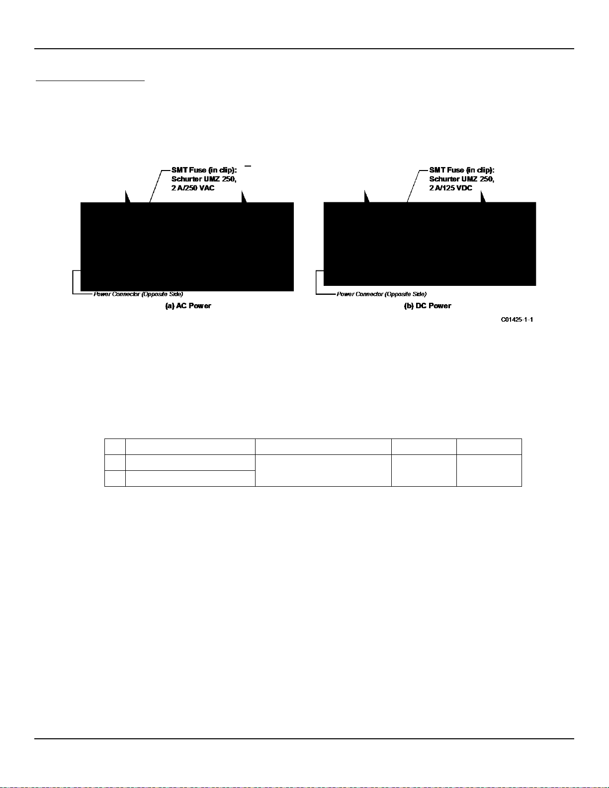
MAINTENANCE ST80/ST80L Flow Meter
Warning:
Make sure system power is OFF before replacing the fuse.
Qty
FCI Assembly P/Ns
Description
Mfgr. P/N
FCI P/N
1
025806-01 (AC-DC Power Supply)
1
025810-01 (DC-DC Power Supply)
Power Fuse Replacement
Input power overload protection is provided by a clip-mounted SMT fuse. Table 25 below summarizes the ST80/ST80L power fuse. Open
the blind lid (refer to instructions in Accessing the I/O Connectors, page 21) to access the power fuse. The fuse is on the opposite side of
the P1 power connector near the edge of the power supply board. See Figure 52 below. Although a plastic shield covers this area of the
board, the fuse remains accessible.
Figure 52 – Fuse Location, Power Supply Board
Checking/Replacing the Fuse
To check the SMT fuse first turn instrument power OFF. Replace a fuse with obvious damage (e.g., burnt, broken). Take a resistance
reading across the fuse (fuse clip ends). See Figure 52 above. Any reading other than a short (i.e., open circuit) indicates a blown fuse.
Replace with the appropriate Schurter UMZ 250 fuse as listed in Table 25 below. Reinstall the blind lid.
Table 25 – Power Fuse Summary
SMT fuse (in clip), Schurter UMZ 250,
2 A, 250 VAC/125 VDC, time-lag
3404.2419.11 026095-02
78 Fluid Components International LLC
Page 87
ST80/ST80L Flow Meter MAINTENANCE
Qty
FCI Assembly P/Ns
Description
Mfgr. P/N
FCI P/N
3V Lithium battery type CR2450N,
Caution:
Warning:
Lithium Battery Replacement
A 3-volt lithium coin cell battery powers the ST80/ST80L real time clock (RTC). Typical service life of the battery is two years. Replace the
battery every two years with the CR2450N coin cell battery listed in Table 26 below.
Table 26 – Lithium Coin Cell Battery Summary
1 025740-01 (Main Board)
540 mAh, temperature range: -40 °C
CR2450N 022038-01
– +85 °C, Manufacturer: Renata
Use only the recommended industrial spec battery listed above. A consumer grade battery will not fit well in the
holder and is prone to leakage or reduced performance or both when used in an industrial environment.
Disassemble the electronics to access the battery. Figure 53 below gives an exploded view of the instrument. Remove the instrument’s
blind lid (refer to instructions in Accessing the I/O Connectors, page 21) and follow the disassembly instructions below (skip steps 3
through 6 if unit has no display). The number callouts in the figure correspond to the numbered steps below.
Make sure system power is OFF before replacing the battery.
1. Remove all user cabling/wiring from the instrument connectors, and then pull all cable/wiring from the cable/wiring ports.
2. Using a 3 mm hex key, remove 2X M4 socket head cap screws securing electronics/cage assembly to housing, and 1X M4 socket
head cap screw securing ground wire to housing. Remove electronics/card cage assembly from housing.
3. Separate bezel/HMI sensor assembly from the cage by pulling straight out.
4. Remove HMI jumper cable from the pin socket at the top the bezel/HMI sensor assembly (Figure 53).
5. Remove 3X 18-8 drive screws securing the display to the cage. Carefully pull the display assembly away from the cage to expose the
FFC (flat flexible cable) cable.
6. Open the FFC cable connector on the main board: Pull the FFC connector lock tab out and then up (away from the board). Once the
lock tab is opened, pull the FFC cable from the connector. Refer to the FFC connector detail in Figure 53. Carefully set aside the fully
detached display assembly.
7. Remove 2X nylon snap rivets securing electronics assembly to the cage, and then slide electronics assembly out to clear the cage.
8. Pull the lithium coin battery from its holder on the main board.
9. Install replacement battery type CR2450N in the coin cell holder with the positive (+) side facing the main board connectors. Use the
replacement battery listed in Table 26 above.
10. Reassembly is reverse of removal. (Make sure FFC display cable is fully inserted and square in connector before pushing the lock tab
back into closed position.)
Fluid Components International LLC 79
Page 88

MAINTENANCE ST80/ST80L Flow Meter
Figure 53 – Instrument Disassembly for Lithium Coin Cell Battery (CR2450N) Replacement
80 Fluid Components International LLC
Page 89

ST80/ST80L Flow Meter TROUBLESHOOTING
Warning:
Caution:
The flow transmitter contains electrostatic discharge (ESD) sensitive devices. Use standard ESD precautions when
5 TROUBLESHOOTING
Instrument testing/troubleshooting limited to qualified personnel only. The operator assumes all responsibilities for
safe practices while troubleshooting.
handling the flow transmitter. See ESD Precautions, page 16 for details.
Non-Maintenance Observations
At this point, observe the system setup to verify operation. No disassembly or testing is required at this time.
Check Serial Numbers
Verify that the serial number of the flow element(s) and the flow transmitter are the same. The flow element(s) and the flow transmitter are
a matched set. Neither can work independently of the other nor can they be swapped with similar units from another system.
Check Input Power
Check for intact fuses. Verify that the AC power source is connected and turned on.
Check Instrument Installation
Review the instrument installation information given in the Installation section to verify correct mechanical and electrical installation. Be sure the
connectors are firmly mated, and the wires are firmly attached to the connector. (Be sure the wires are inserted between the metal clamps and n ot
between the clamp and plastic connector enclosure.) Verify correct wiring per wiring diagram in APPENDIX A, page 93.
Check for Moisture
Check for moisture in the enclosures. Moisture on the electronics can cause faulty operation.
If a component of the process media is near its saturation temperature, then the component may condense on the sensing points. Liquid
on the sensing points can cause measurement errors.
Check Application Design Requirements
Application design problems usually occur with first time application instruments, although the design should also be checked on
instruments that have been in operation for some time. If the application design does not match field conditions, errors occur.
1. Review the application design with plant operation personnel and plant engineers.
2. Ensure that plant equipment such as pressure and temperature instruments conform to the actual conditions.
3. Verify operating temperature, operating pressure, line size, and gas medium.
Check the General Process
Check all inputs and outputs to the system. Verify pump ratings and check damper or valves that might be open or closed causing the flow
to be different from that which would be expected.
Fluid Components International LLC 81
Page 90

TROUBLESHOOTING ST80/ST80L Flo w Meter
Verify Standard vs. Actual Process Conditions
The flow meter measures the mass flow rate. The mass flow rate is the mass of the gas flowing through a pipe per time. Other flow meters,
such as an orifice plate or a pitot tube, measure the volumetric flow rate. The volumetric flow rate is the volume of gas per time. If the
readings displayed do not agree with another instrument, some calculations may be necessary before comparing them. To calculate the
mass flow rate and the volumetric flow rate the pressure and temperature at the point of measurement must be known. Use the following
equation to calculate the mass flow rate (Standard Volumetric Flow rate) for the other instrument.
Equation:
Where:
= Volumetric Flow QS = Standard Volumetric Flow
Q
A
P
= Actual Pressure TA = Actual Temperature
A
P
Pressure in PSIA and Temperature is in degrees Rankine
= Standard Pressure TS = Standard Temperature
S
Example:
General Function Check
Tools Needed
● Digital M ultimeter (DMM)
● ST80/ST80L Configuration Software Application
● USB Cable Type B (male) to Type A (male); passive, straight-through type as supplied with instrument
● Small size flat blade screwdriver (for sensor wiring connection)
Verifying Setup
Connect the flow meter via USB to a computer or laptop running the ST80/ST80L configuration software supplied with the instrument.
Refer to the ST80/ST80L Configuration Software manual 06EN003491 for details.
Confirm the setup of the flow meter by reviewing the setup windows in the configurator. Contact your local representative or FCI for
instructions if a setup discrepancy exists.
Checking NAMUR Fault Indication
If the instrument’s flow output is set up for NAMUR, check the output to see if it is driven to a NAMUR level. Refer to NAMUR Setup, page
41 for NAMUR information. Refer to Table 8 on page 42 for the list of faults that trigger NAMUR.
82 Fluid Components International LLC
Page 91
ST80/ST80L Flow Meter TROUBLESHOOTING
Term
Number
TB1-1
(Htr Exc)
TB1-2
(Htr Rtn)
TB1-3
(Act Exc)
TB1-4
(Act Sen)
TB1-5
(Gnd Sen)
TB1-6
(Gnd)
TB1-7
(Ref Exc)
TB1-8
(Ref Sen)
TB1-1
(Htr Exc)
TB1-2
(Htr Rtn)
TB1-3
(Act Exc)
TB1-4
(Act Sen)
TB1-5
TB1-6
(Gnd)
TB1-7
(Ref Exc)
TB1-8
(Ref Sen)
Note:
Term
Number
1
N/A
01
10802
10802
10802
10802 ∞ ∞ 2 01
N/A
10802
10802
10802
10802 ∞ ∞ 3 10802
10802
N/A
21602
01
21602 ∞ ∞ 4 10802
10802
21602
N/A
21602
01 ∞ ∞
5
10802
10802
01
21602
N/A
21602 ∞ ∞
6
10802
10802
21602
01
21602
N/A ∞ ∞
7 ∞ ∞ ∞ ∞ ∞ ∞
N/A
1153
8 ∞ ∞ ∞ ∞ ∞ ∞
1153
N/A
Troubleshooting the Flow Element
Check the Resistance of the Flow Element
Turn flow transmitter power OFF. Remove the TB1 connector plug from the sensor wiring pin socket (pull plug straight out).
Measure the resistance between the terminals of the pulled connector plug and compare with the values shown in Table 27 below.
Table 27 – Flow Element Resistance Measurements (In Ohms) Taken From Remote/Integral Electronics
N/A 1153 ∞ ∞ ∞ ∞ ∞ ∞
1153 N/A ∞ ∞ ∞ ∞ ∞ ∞
∞ ∞ N/A 01 10802 10802 21602 21602
∞ ∞ 01 N/A 10802 10802 21602 21602
(Gnd Sen)
∞ ∞ 10802 10802 N/A 01 10802 10802
∞ ∞ 10802 10802 01 N/A 10802 10802
∞ ∞ 21602 21602 10802 10802 N/A 01
∞ ∞ 21602 21602 10802 10802 01 N/A
Notes: 1. Theoretical zero-ohm table values are influenced by sensor cable length, which typically adds <2 Ω.
2. Resistances are approximate for a sensor temperature of 70 °F (21 °C).
3. Heater resistance range is 108-120 Ω.
There is added resistance to consider when measuring the flow element from the remote transmitter. The cable adds
extra resistance. The added resistance can be found by measuring the ACT SEN wire to the ACT EXC wire (e.g.,
TB1-4 to TB1-3.).
For Remote Units – If the measured values do not match that shown in the above table, unplug the cabling connecting the local enclosure
flow element to the remote transmitter and measure the resistance between the terminals of the flow element assembly terminal strip TS1.
Compare the measured values with the values shown in Table 28 below.
Table 28 – Flow Element Resistance (In Ohms) at the Local Enclosure
1 2 3 4 5 6 7 8
Notes: 1. Theoretical zero-ohm table values are influenced by sensor cable length, which typically adds <2 Ω.
2. Resistances are approximate for a sensor temperature of 70 °F (21 °C).
3. Heater resistance range is 108-120 Ω.
If the instrument has been on for some time, the resistance of the active RTD will be greater than the reference RTD.
Fluid Components International LLC 83
Page 92

TROUBLESHOOTING ST80/ST80L Flo w Meter
Heater Configuration
Resistance
Voltage
Current
AST™
108-120 Ω
4.32-12.6 V
40-105 mA
Constant Power
108-120 Ω
7.884-9.24 V
75 mA ±2 mA
If the instrument has been off for some time, the resistance of the active RTD will be the same as the reference RTD.
For Remote Units – If the measured resistances correspond to Table 28, but not to Table 27, then the sensor interconnect cable is
probably defective. Replace the cable and recheck resistances. If the resistances are still off, contact Customer Service.
If the measured values do not correspond to Table 27 or Table 28 (for remote units), then the flow element is defective. Contact Customer Service.
Reinstall the sensor plug(s) and reattach the cables when troubleshooting is complete.
Check the Heater
Use the configuration software to check the heater as follows (refer to the ST80/ST80L Configuration Software manual 06EN003491 for
software details):
1. Access the Heater Values tab from the Diagnostics branch of the menu tree. See Figure 54 below.
2. Click Start Data Loop. Note that the button changes color when clicked (light green to light orange).
3. Verify that the displayed values for Heater Resistance, Heater Voltage, and Heater Current mA are within normal parameters.
Click Stop Data Loop when done. See Table 29 below.
Table 29 – Nominal Heater Parameter Ranges
Figure 54 – Example Heater Values Tab (Diagnostics)
84 Fluid Components International LLC
Page 93
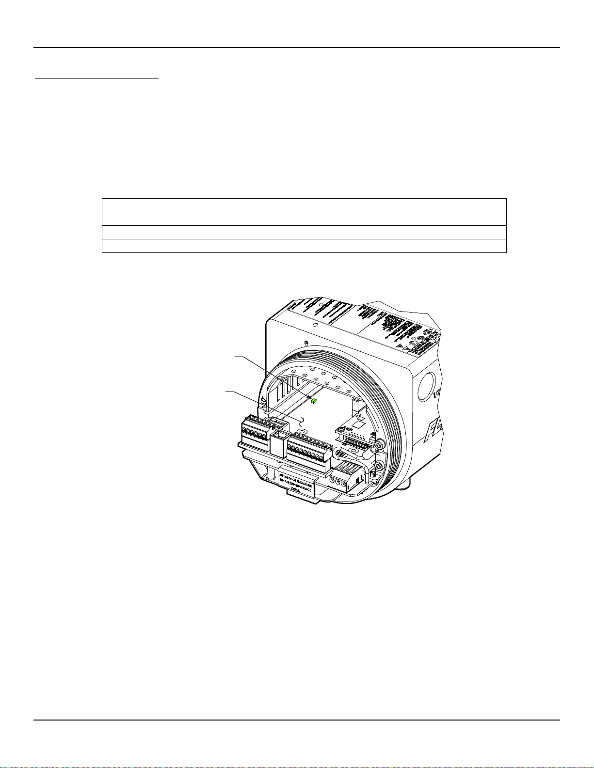
ST80/ST80L Flow Meter TROUBLESHOOTING
Warning:
Explosion Hazard. Do not disconnect equipment when flammable or combustible atmosphere is present. Operator
Note:
The information in this section applies to both AST™ and Constant Power configured instruments.
System Status LED (D3), State
Description
Slow blink (blink every 2 seconds)
Normal operation.
OFF
No power or power supply issue, or system controller halted (hang).
ON (no blink, continuous)
System controller halted (hang).
Note:
Should any of these checks fail, contact FCI Technical Support for assistance.
C01464-1-1
MAIN BOARD
SYSTEM STATUS LED,
D3
Verification of the Electronics
assumes responsibility for all safety concerns relating to interrupting and reapplying power to their instrumentation.
With instrument power ON remove the instrument’s blind lid (see Accessing the I/O Connectors, page 21). Check the green system status
LED on the main board (see Figure 55 below). The system status LED states are listed in the table below.
Table 30 – System Status LED D3 States
Cycle the power to see if the instrument recovers from a possible system controller hang. Contact FCI Technical Support for assistance if the
system status LED is still not blinking.
Figure 55 – System Status LED, Main Board
After checking the system status LED, verify the electronics with the three checks summarized below (there is no sequence in performing
these checks).
Transmitter Power Supply Check via configuration software: Factory|Sil Adj tab (see Transmitter Power Supply, below). Make sure
that the displayed power supply voltages are within range.
Heater Check via configuration software: Diagnostics|Heater Values tab (see Check the Heater, above). Make sure that the heater
resistance, voltage, and current are within range.
Internal Delta-R Resistor (idR) Check via HMI display or configuration software: Diagnostics/idR Scheduled Tests tab (see Internal
Delta-R Resistor (idR) Check, page 43). After running the idR check, verify that the Low, Mid, and High range values show “Passed.”
Fluid Components International LLC 85
Page 94
TROUBLESHOOTING ST80/ST80L Flo w Meter
Power Supply Voltage
Acceptable Voltage Range
Digital 5 VDC
+4.75 V to +5.25 V
Analog 24 VDC
+23.75 V to +24.25 V
Transmitter Power Supply
Use the ST80/ST80L configuration software to check the power supply voltages. Refer to ST80/ST80L Configuration Software manual
06EN003491 for details. Select the Factory branch from the menu tree on the window's left side. Select the SIL Adj tab. The screen shows
power supply voltage readings for +24 VDC and +5 VDC. Check that the displayed values are within range as listed in Table 31 below.
Table 31 – Instrument Power Supply Voltages
If the voltage measurements are within the range shown in the table, the power supply is functioning properly.
86 Fluid Components International LLC
Page 95
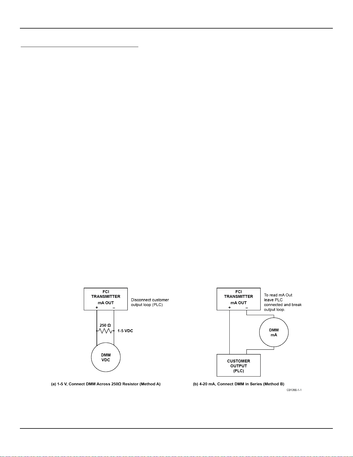
ST80/ST80L Flow Meter TROUBLESHOOTING
Note:
Constant Power Configuration Troubleshooting
Equipment List
● 250 Ω 0.01% resistor
● 2 digital multimeters (DMM)
● Delta R Calibration Data Sheet (serial number specific by instrument and group)
● FES-200 flow element simulator
● FES-200 interface cable for ST80/ST80L (022610-11)
Alternative to FES-200:
● 2 ea. Precision Decade Resistance Box, 0.1% (1 kΩ large step, 0.01 Ω small step)
Delta R Check for Constant Power Configured Units
If the flow meter’s parameters have been changed, calibrations may be inaccurate or factory authorized changes
have been made. Consult a factory service representative.
Each flow meter configured at the factory for Constant Power is provided with a Delta R data sheet that lists the differential resistance
values that correlate to the flow meter’s calibration. Resistance substitution instruments like the FES-200 can be used to check instrument
calibration and verify correct operation of the flow transmitter using the Delta R data sheet.
To verify the transmitter is working properly, the sensor head must be disconnected and precision resistance (Delta R) values from the
FES-200 are substituted. Then by measuring the transmitter output and display it can be determined whether the transmitter is still within
factory specification.
Delta R Check
1. Verify the Delta R data sheet has the same serial number and group number as the flow meter calibration that is being verified.
2. Turn transmitter power OFF.
3. Disconnect a flow element sensor from the ST80/ST80L transmitter (TB1) and connect the FES-200 cable connector in its place. See
Figure 57. Precision decade boxes can be used in place of the FES-200. See Figure 58 for decade box wiring.
4. Connect a DMM to the transmitter 4-20 mA output by either method A or B as shown in Figure 56 below.
a. To read 1 to 5 volts, disconnect both output loop wires and connect a precision 250 Ω resistor across the output terminal. Then
connect the DMM, set to DC volts (V), across the resistor to read its voltage drop.
b. To read 4 to 20 mA current, disconnect the output loop and connect the DMM, set to milliamps (mA), in series with the output
circuit to read the current flow.
Figure 56 – DMM Hookup to Measure 4-20 mA Output
5. Turn transmitter power ON and allow the instrument 10 minutes to stabilize.
Fluid Components International LLC 87
Page 96
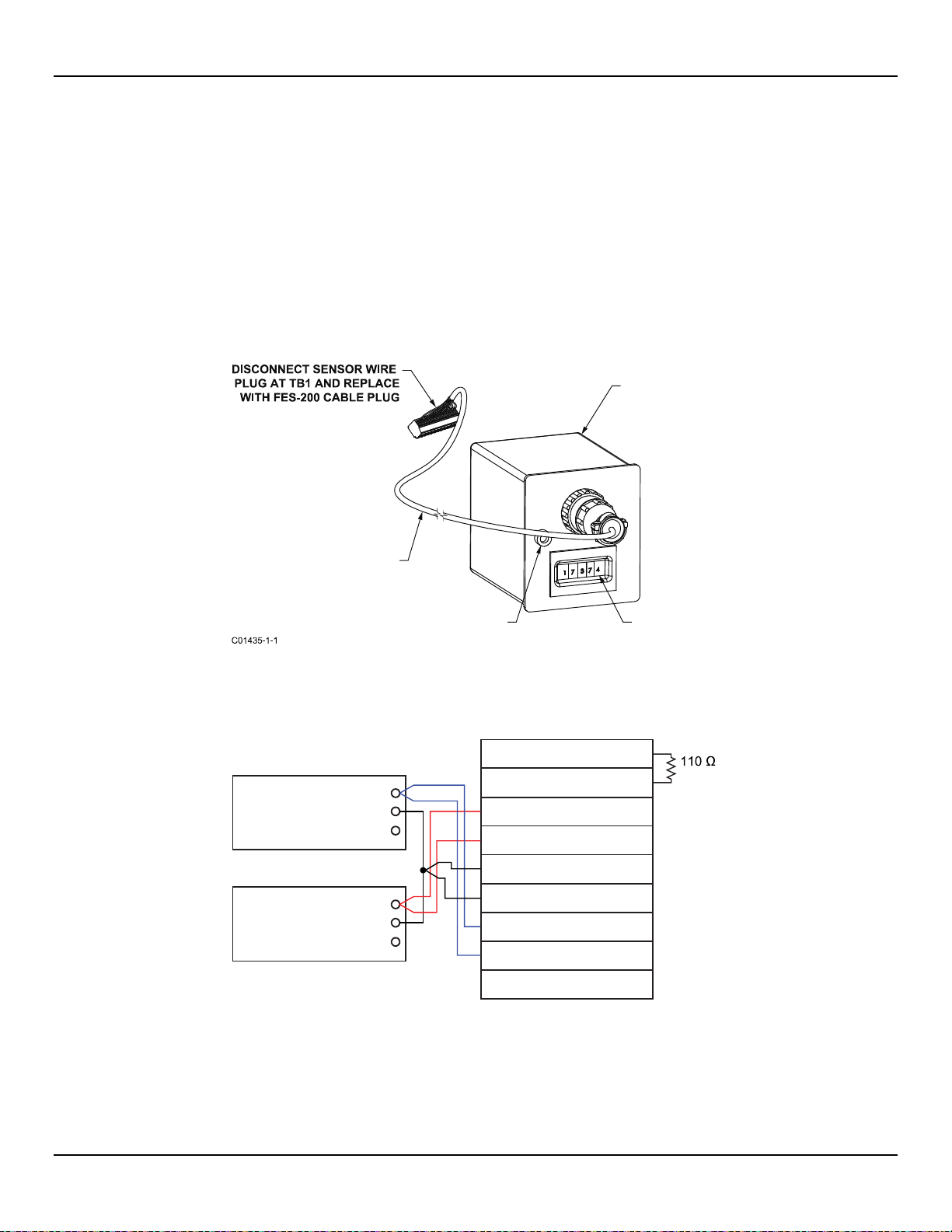
TROUBLESHOOTING ST80/ST80L Flo w Meter
REMOTE ELECTRONICS
FES-200 CABLE
FOR ST80/ST80L
TP1 HEATER
CURRENT
THUMBWHEEL
SWITCHES
FES-200
FLOW ELEMENT
SIMULATOR
Reference Sens
or
H
L
G
Active Sensor
H
L
G
1 HTR EXC #1
2 HTR RTN
3 ACT EXC
4 ACT SEN
5 GND SEN
6 GND/SHIELD
7 REF EXC
8 REF SEN
9 SHIELD
TB1
10 W
C01436-1-1
6. Verify the transmitter is in the calibration group matching the Delta R data sheet.
7. On the FES-200, dial in a Delta R value with the thumbwheel from the column marked Delta R (ohms) on the Delta R data sheet. Compare to
the output value column (VDC Across 250 Ohms or mA Output as applicable) or the Indicated Display column or both. Verify that the meter
reading is within the stated tolerance of the flow transmitter. See examples 1, 2 and 3 at the end of this section, as applicable.
8. Repeat for each point on the Delta R table, except for the step value and zero value.
9. Turn power OFF and disconnect the FES-200 and DMM. Reconnect the sensor element connector.
10. Close the enclosure, making sure none of the wires are strained. Ensure any seals and gaskets are properly installed.
11. Restore power to the meter.
If you are troubleshooting the flow meter and the readings are good, the flow transmitter is good and the problem may involve the flow
element or interconnecting cable. If the readings are off, a flow element calibration may be required or the flow transmitter needs to be set
up. Contact FCI Customer Service.
Figure 57 – Connecting FES-200 to ST80/ST80L Transmitter
Figure 58 – ST80/ST80L Decade Box Wiring
88 Fluid Components International LLC
Page 97

ST80/ST80L Flow Meter TROUBLESHOOTING
Note:
Since the 1-5 VDC range starts at 1 VDC, account for this offset by subtracting 1 VDC from both the “reading” of
Note:
Since the 4-20 mA range starts at 4 mA, account for this offset by subtracting 4 mA from both the “reading” of 11.98
Note:
Allowable Limits
Example 1 - 4-20 mA output check using 1-5 VDC measurement.
Accuracy: ±(0.75% reading + 0.5% full scale) from GF90 Manual
Example Delta R Table entry:
Delta R (ohms)
VDC Across
250 ohms
mA Output Unit dR
Indicated
Display
71.08 2.995 11.98 71.197 154.8 SCFM
• Measure VDC with FES-200 thumbwheel set to 071.08 = 3.011 VDC measured on DMM.
• Determine allowable VDC limits for the 2.995 VDC table value:
2.995 VDC and the “full scale” of 5 VDC.
• Allowable VDC limits = 0.0075 x (2.995 – 1) + 0.005 x (5 – 1) = ±0.035 VDC
The measured value of 3.011 VDC is within the allowable limits of 2.995 ±0.035 VDC.
Example 2 - 4-20 mA output check (using example 1 sample data)
• Measure m A with FES-200 thumbwheel set to 071.08 = 12.04 mA measured on DMM.
• Determine allowable mA limits for the 11.98 mA table value:
mA and the “full scale” of 20 mA.
• Allowable mA limits = 0.0075 x (11.98 – 4) + 0.005 x (20 – 4) = ±0.139 mA
The measured value of 12.04 mA is within the allowable limits of 11.98 ±0.139 mA.
Example 3 - Indicated Display Check (using information from above examples)
• Record the indicated display value with FES-200 thumbwheel set to 071.08 = 156 SCFM indicated on display.
• Determine allowable limits for the 154.8 SCFM table value:
• Allowab le Indicated flow limits = 0.0075 x 154.8 SCFM + 0.005 x 310 SCFM = ± 2.71 SCFM
The indicated value of 156 SCFM is within the allowable limits of 154.8 ±2.71 SCFM.
Defective Parts
Before returning any equipment to FCI, obtain an RA number for authorization, tracking, and repair/replacement instructions. If a return is
required, remove the defective part, replace with a spare, calibrate, then return defective part to FCI, freight prepaid, for disposition.
Customer Service
1. In the event of problems or inquiries regarding the instrument, contact an authorized FCI field agent for the region or country. Refer to
the FCI website: http://www.fluidcomponents.com/ for a list of field service representatives (which includes phone and email contact
information) and a list of service centers around the world.
2. Before contacting the FCI representative make sure that all the applicable information is near so that a more effective, efficient and
timely response can be provided.
3. Refer to APPENDIX E, page 143 for specific Customer Service policy provisions.
The full scale display value is 310 SCFM in this example.
Fluid Components International LLC 89
Page 98
TROUBLESHOOTING ST80/ST80L Flo w Meter
1
0x00000004 t o
0x00000100 t o
2-2
PD_NON_OP
At least one FE was non-operational (self-test)
Non-Fatal
0x00040000
2-3
PD_SYSTEM_ERROR
System (Core) error
Non-Fatal
0x00080000
2-5
PD_NO_PD_UPDATE
All FEs reported a fatal error
Fatal
0x00200000
2-6
PD_SD_CARD_ERROR
SD Card error
Non-Fatal
0x00400000
Reference: Error/Status Register Information
Summarized below are various registers that provide the instrument with error/status information. This information is normally presented in
the configuration software’s Fault Log tab. Digital busses (such as HART) can also access this information via a read operation using the
appropriate register address.
Instrument Fault Codes Tables
The basic CORE fault register (4 bytes) provides basic CORE and FE fault indication. Detailed faults are given in the 6-byte detailed
CORE fault register and the 4-byte FE fault register. The latter two registers provide specific error status for a fault indicated by the basic
CORE fault register.
Table 32 – Basic CORE Fault Register (CORE CY Command)
Octet-Bit
0-0
FE_01_FAULT
0-1
FE_02_FAULT
0-2 to 0-7
1-1 to 1-8
2-0
PD_FATAL_FAULT
2-1
2-4
2-7
3-0 to 3-1
3-2
Process Alarm #1
3-3
Process Alarm #2
3-4
Process Alarm #3
3-5
Process Alarm #4
3-6
Process Alarm #5
3-7
Process Alarm #6
Note: 1. Fault Type reflects factory default programming. The Fatal/Non-Fatal designation is programmable via the Configurator
software’s Core Faults tab (Factory branch menu tree – requires entry of appropriate level password).
Fault Name
Fault Description
FE1 is reporti ng a fault or an error
FE2 is reporti ng a fault or an error (ST100A)
FCI Reserve d (Not Used)
FCI Reserve d (Not Used)
At least one FE has a fatal error or fault
FCI Reserve d (Not Used)
FCI Reserve d (Not Used)
FCI Reserve d (Not Used)
FCI Reserve d (Not Used)
Alarm #1 Status (1 = Tripped)
Alarm #2 Status (1 = Tripped)
Alarm #3 Status (1 = Tripped)
Alarm #4 Status (1 = Tripped)
Alarm #5 Status (1 = Tripped)
Alarm #6 Status (1 = Tripped)
Fault Type
Fatal/Non-Fatal 0x00000001
Fatal/Non-Fatal 0x00000002
Fatal
Non-Fatal
Non-Fatal
Non-Fatal
Non-Fatal
Non-Fatal
Non-Fatal
Hex Bit Map
0x00000080
0x00008000
0x00010000
0x00020000
0x00100000
0x00800000
0x01000000 t o
0x02000000
0x04000000
0x08000000
0x10000000
0x20000000
0x40000000
0x80000000
90 Fluid Components International LLC
Page 99
ST80/ST80L Flow Meter TROUBLESHOOTING
Octet-Bit
Status Description
Fault Type
Hex Bit Map
0-0
Device Error: If any of these errors occurs: I2C error, UART error, Mutex error, watchdog reset
Fatal
0x000000000001
0-1
FCI Reserve d (Not Used)
Non-Fatal
0x000000000002
0-2
FCI Reserve d (Not Used)
Non-Fatal
0x000000000004
0-3
CORE unable to update process data (PD_NO_FE_DATA). Unable to obtain/use data from any Active FEs
Fatal
0x000000000008
0-4
FCI Reserve d (Not Used)
Non-Fatal
0x000000000010
0-5
CORE detects FRAM /SPI error
Fatal
0x000000000020
0-6
CORE reports SD card error. Either initialization (corrupt card) error, or card became full (error while writin g). For ST100A only.
Non-Fatal
0x000000000040
0-7
FCI Reserve d (Not Used)
Non-Fatal
0x000000000080
1-0
FCI Reserve d (Not Used)
Non-Fatal
0x000000000100
1-1
FCI Reserve d (Not Used)
Non-Fatal
0x000000000200
1-2
FCI Reserve d (Not Used)
Non-Fatal
0x000000000400
1-3
FCI Reserve d (Not Used)
Non-Fatal
0x000000000800
1-4
FCI Reserve d (Not Used)
Non-Fatal
0x000000001000
1-5
CORE unable to communicate with one or more FEs (PD_COMM_E RROR)
Fatal
0x000000002000
1-6
FCI Reserve d (Not Used)
Non-Fatal
0x000000004000
1-7
CORE: averaged flow out of range of “Flow Min” or “Flow M ax”
Non-Fatal
0x000000008000
2-0
FCI Reserve d (Not Used)
Non-Fatal
0x000000010000
2-1
FCI Reserve d (Not Used)
Non-Fatal
0x000000020000
2-2
FCI Reserve d (Not Used)
Non-Fatal
0x000000040000
2-3
CORE: avera ged temperature above “Temperature Max”
Fatal
0x000000080000
2-4
CORE: averaged temperature below “Temperature Min”
Fatal
0x000000100000
2-5
FE Heater is shorted or below operating limit.
Fatal
0x000000200000
2-6
FE Heater moni toring ADC fails to respond.
Fatal
0x000000400000
2-7
FE Heater is open or above operating limit.
Fatal
0x000000800000
3-0
The Referenc e-R ADC converter fails to respond.
Fatal
0x000001000000
3-1
FCI Reserve d (Not Used)
Non-Fatal
0x000002000000
3-2
The Referenc e-R ADC’s count number is below the minimum.
Non-Fatal
0x000004000000
3-3
FCI Reserve d (Not Used)
Non-Fatal
0x000008000000
3-4
Process flow is above the maximum limi t.
Non-Fatal
0x000010000000
3-5
FCI Reserve d (Not Used)
Non-Fatal
0x000020000000
3-6
FCI Reserve d (Not Used)
Non-Fatal
0x000040000000
3-7
The ADC for monitoring the temperature inside the unit fails to respond.
Non-Fatal
0x000080000000
4-0
The Delta-R ADC fails to respond.
Fatal
0x000100000000
4-1
ST80: Not use d. ST100A: 4-20mA Input / Pressure Input ADC fails to respond.
Non-Fatal
0x000200000000
4-2
Reference-R value is above operating l imit.
Non-Fatal
0x000400000000
4-3
The Inter-Integrated Circuit channel 0 bus fails to communicate.
Non-Fatal
0x000800000000
4-4
The ADC for monitoring heater’s conditions fails to respond.
Fatal
0x00100000000
4-5
The port expansion integrated chip fai ls to respond.
Non-Fatal
0x00200000000
4-6
FCI Reserve d (Not Used)
Non-Fatal
0x00400000000
4-7
FCI Reserve d (Not Used)
Non-Fatal
0x00800000000
5-0
The FRAM of the Flow Element fails to respond.
Non-Fatal
0x01000000000
5-1
The Active excitation current Integrated Circuit (IC) fails.
Non-Fatal
0x02000000000
5-2
The Reference ex ci tation current Integrated Circuit (IC) fails.
Non-Fatal
0x04000000000
5-3
CORE: process data are not updated because (all) FE's are in self-test mode, or the system is in non-operating mode.
Non-Fatal
0x08000000000
5-4
Reference-R value is below operating limit.
Non-Fatal
0x10000000000
5-5
Delta-R value is above operating limit.
Non-Fatal
0x20000000000
5-6
Delta-R value is below operating limit.
Non-Fatal
0x40000000000
5-7
The unit is performing a (diagnostic ) test.
Non-Fatal
0x80000000000
Table 33 – Detailed CORE Fault Register (CORE 2V Command)
Notes: 1. Fault Type reflects factory default programming. The Fatal/Non-Fatal designation is programmable via the Configurator
software’s FE Faults tab (Factory branch menu tree – requires entry of appropriate level password).
Fluid Components International LLC 91
Page 100
TROUBLESHOOTING ST80/ST80L Flo w Meter
Octet-Bit
Fault Name
Fault Description
Fault Type1
Hex Bit Map
0-0
FCI Reserve d (Not Used)
—
—
0x00000001
0-1
FCI Reserve d (Not Used)
—
—
0x00000002
0-2
The heater current analog-to-digital converter shows
0-3
FCI Reserve d (Not Used)
—
—
0x00000008
0-4
FCI Reserve d (Not Used)
—
—
0x00000010
0-5
FCI Reserve d (Not Used)
—
—
0x00000020
0-6
SENSOR_ABOVE_MAX_FLOW_FAULT
Process flow is above the maximum limi t.
Fatal
0x00000040
0-7
SENSOR_OVER_TEMP_FAULT
Process tem perature is above the maximum limit.
Fatal
0x00000080
1-0
SENSOR_UNDER_TEMP_FAULT
Process tem perature is below the minimum limit.
Fatal
0x00000100
The heater is shorted or its value is below the normal
operating value.
The heater is open or its value is above the normal
operating value.
The heater current analog-to-digital converter (ADC) fails
to respond.
1-4
dR_ADC_FAULT
The Delta-R ADC fails to respond.
Fatal
0x00001000
1-5
REF_ADC_FAULT
The Referenc e-R ADC converter fails to respond.
Fatal
0x00002000
Temperature inside the unit is outsi de the limits (above or
below the op erating limits).
The Inter-Integrated Circuit (I2C) channel 0 bus fails to
communicate.
The Referenc e-R ADC’s count number is below the
minimum.
2-2
FCI Reserve d (Not Used)
—
—
0x00020000
2-2
PORT_EXPANDER_FAULT
The port expansion integrated chip fai ls to respond.
Non-Fatal
0x00040000
2-3
BELOW_dR_MIN_FAULT
Delta-R value is below minimum limit.
Fatal
0x00080000
The ADC for monitoring the temperature inside the unit
fails to respond.
2-5
LTC2654_DAC_FAULT
The digital-to-a nalog converter fails t o respond.
Non-Fatal
0x00200000
2-6
FE_FRAM_FAULT
The FRAM of the Flow Element fails to respond.
Non-Fatal
0x00400000
2-7
FCI Reserve d (Not Used)
—
—
0x00800000
The ADC for monitoring heater’s conditions fails to
3-1
ACT_EXC_CURR_FAULT
The Active excitation current Integrated Circuit (IC) fails.
Non-Fatal
0x02000000
The Referenc e excitation current Integrated Circuit (IC)
fails.
3-3
SENSOR_REFR_ABOVE_ABS_MAX
Reference-R value is above operating l imit.
Fatal
0x08000000
3-4
SENSOR_REFR_BELOW_ABS_MIN
Reference-R value is below operating l imit.
Non-Fatal
0x10000000
3-5
SENSOR_DR_ABOVE_ABS_MAX
Delta-R value is above operating limit.
Non-Fatal
0x20000000
3-6
SENSOR_DR_BELOW_ABS_MIN
Delta-R value is below operating limit.
Fatal
0x40000000
3-7
FE_AUTO_CHECK
The unit is performing a (diagnostic ) test.
Fatal
0x80000000
Table 34 – FE Fault Register (FE DF Command)
HTR_CURR_ADC_OVER_RANGE_FAULT
1-1 HEATER_SHORTED_FAULT
1-2 HEATER_OPEN_FAULT
1-3 HTR_CURR_ADC_FAULT
1-6 BRD_TEMP_LIMITS_FAULT
1-7 I2C0_FAULT
2-0 SENSOR_BELOW_MIN_ADC_FAULT
2-4 TMP100_ADC_FAULT
saturation at its input.
Fatal 0x00000004
Fatal 0x00000200
Fatal 0x00000400
Non-Fatal 0x00000800
Fatal 0x00004000
Fatal 0x00008000
Fatal 0x00010000
Non-Fatal 0x00100000
3-0 HTRS_MON_ADC_FAULT
3-2 REF_EXC_CURR_FAULT
respond.
Non-Fatal 0x01000000
Non-Fatal 0x04000000
Notes: 1. Fault Type reflects factory default programming. The Fatal/Non-Fatal designation is programmable via the Configurator
software’s FE Faults tab (Factory branch menu tree – requires entry of appropriate level password).
92 Fluid Components International LLC
 Loading...