

Page 1
5
6
The SS-002-1 oers a congurable mix of any
three of the four internal sensors: Temperature,
Humidity, Barometric Pressure, Ambient Light, AND
one external sensor opon:
Thermocouple, RTD, or DIN (contact closure).
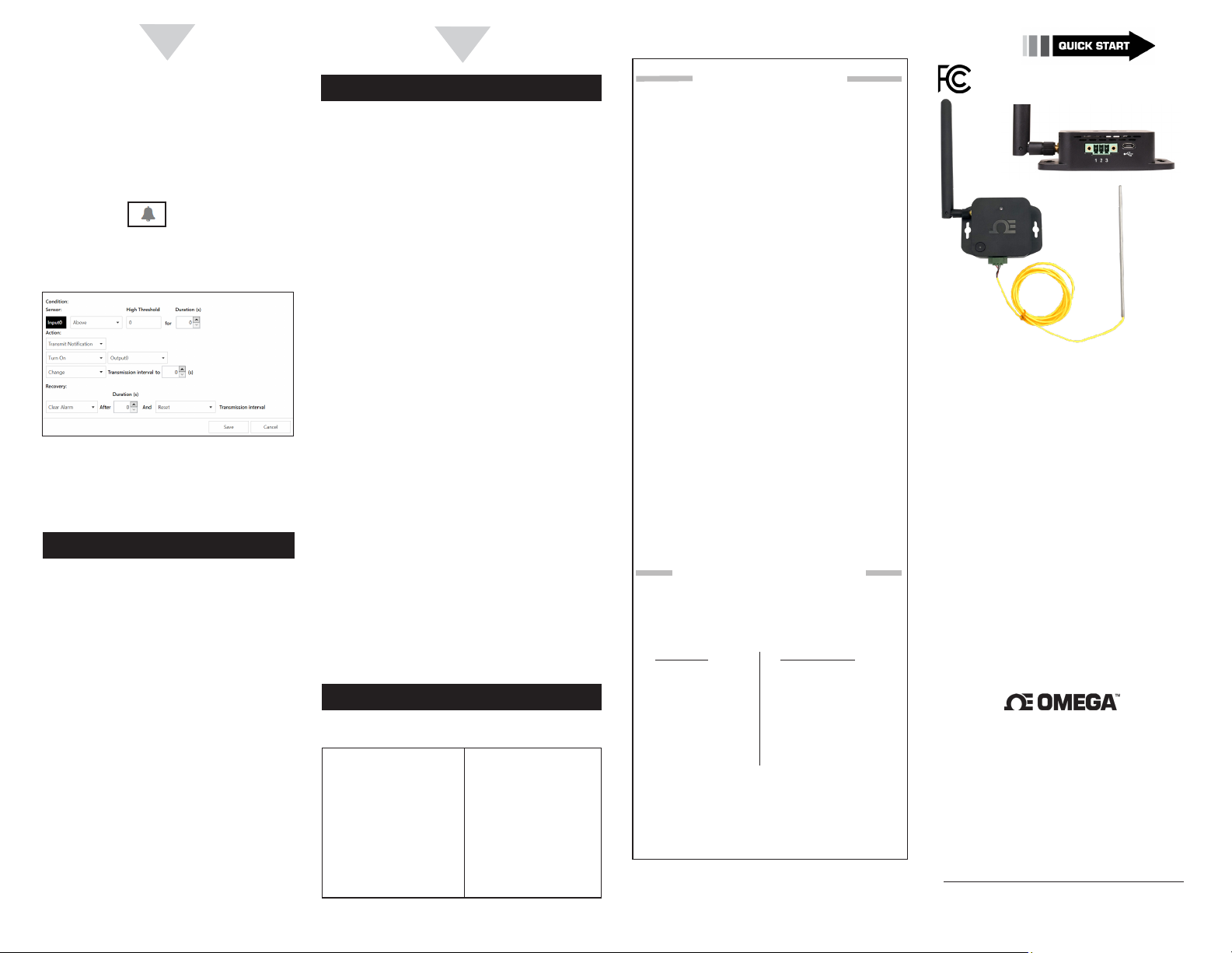
Seng Alarms
To congure the alarms in your SS-002 using SYNC,
follow these steps:
Click the icon next to the input
Step 1:
you wish to set an alarm for.
Step 2: Set the parameters for your alarm and click
Save.
SYNC - Device Sengs
Users can perform funcons such as rmware
updates and factory resets of the SS-002 by
navigang to the Device Sengs tab of SYNC
conguraon soware.
SS-002 USB Powered Range Boost
Range Boost Mode
When the SS-002 (-NA) device is powered directly
by a micro USB 2.0, the Smart Sensor will also
enter a Range Boost mode which will enhance the
wireless range or coverage of the Smart Sensor up
to 3.2 km*.
*Clear line of sight. Actual range may vary depending on
environment.
FCC Statement
Contains FCC ID: WR3SS001XNA
This device complies with Part 15 of the FCC Rules. Operaon is
subject to the following two condions: (1) This device may not
cause harmful interference, and (2) this device must accept any
interference received, including interference that may cause
undesired operaon.
This equipment has been tested and found to comply with
the limits for a Class B digital device, pursuant to Part 15
of the FCC Rules. These limits are designed to provide
reasonable protecon against harmful interference in a
residenal installaon. This equipment generates, uses and
can radiate radio frequency energy and, if not installed and
used in accordance with the instrucons, may cause harmful
interference to radio communicaons. However, there is
no guarantee that interference will not occur in a parcular
installaon. If this equipment does cause harmful interference
to radio or television recepon, which can be determined
by turning the equipment o and on, the user is encouraged
to try to correct the interference by one of the following
measures:
• Reorient or relocate the receiving antenna.
• Increase the separaon between the equipment
and receiver.
• Connect the equipment into an outlet on a circuit
dierent from that to which the receiver is
connected.
• Consult the dealer or an experienced radio/TV
technician for help.
FCC Cauon: Any changes or modicaons not expressly
approved by the party responsible for compliance could void
the user’s authority to operate this equipment.
This transmier must not be co-located or operang in
conjuncon with any other antenna or transmier.
FOR MOBILE DEVICE USAGE (>20cm/low power)
Radiaon Exposure Statement:
This equipment complies with FCC radiaon exposure limits
set forth for an uncontrolled environment. This equipment
should be installed and operated with minimum distance 20 cm
between the radiator & your body.
Industry Canada Statement
Contains IC ID: 8205A-SS001XNA
This device complies with Industry
Canada license-exempt RSS
standard(s). Operaon is subject
to the following two condions:
(1) this device may not cause
interference, and (2) this device
must accept any interference,
including interference that may
cause undesired operaon of the
device.
Le présent appareil est conforme
aux CNR d’Industrie Canada
applicables aux appareils
radio exempts de licence.
L’exploitaon est autorisée aux
deux condions suivantes : (1)
l’appareil ne doit pas produire
de brouillage, et (2) l’ulisateur
de l’appareil doit accepter
tout brouillage radioélectrique
subi, même si le brouillage est
suscepble d’en compromere le
fonconnement.
OMEGA ENGINEERING, INC. warrants this unit to be free of defects
WARRANTY/DISCLAIMER
in materials and workmanship for a period of 13 months from
date of purchase. OMEGA’s WARRANTY adds an additional one (1)
month grace period to the normal one (1) year product warranty
to cover handling and shipping time. This ensures that OMEGA’s
customers receive maximum coverage on each product.
If the unit malfunctions, it must be returned to the factory for evaluation. OMEGA’s Customer Service Department will issue an Authorized
Return (AR) number immediately upon phone or written request.
Upon examination by OMEGA, if the unit is found to be defective,
it will be repaired or replaced at no charge. OMEGA’s WARRANTY
does not apply to defects resulting from any action of the purchaser,
including but not limited to mishandling, improper interfacing, operation outside of design limits, improper repair, or unauthorized modification. This WARRANTY is VOID if the unit shows evidence of having
been tampered with or shows evidence of having been damaged as a
result of excessive corrosion; or current, heat, moisture or vibration;
improper specification; misapplication; misuse or other operating
conditions outside of OMEGA’s control. Components in which wear
is not warranted, include but are not limited to contact points, fuses,
and triacs.
OMEGA is pleased to offer suggestions on the use of its various products. However, OMEGA neither assumes responsibility for any omissions or errors nor assumes liability for any
damages that result from the use if its products in accordance
with information provided by OMEGA, either verbal or written. OMEGA warrants only that the parts manufactured by
the company will be as specified and free of defects. OMEGA
MAKES NO OTHER WARRANTIES OR REPRESENTATIONS OF
ANY KIND WHATSOEVER, EXPRESSED OR IMPLIED, EXCEPT
THAT OF TITLE, AND ALL IMPLIED WARRANTIES INCLUDING
ANY WARRANTY OF MERCHANTABILITY AND FITNESS
FOR A PARTICULAR PURPOSE ARE HEREBY DISCLAIMED.
LIMITATION OF LIABILITY: The remedies of purchaser set
forth herein are exclusive, and the total liability of OMEGA
with respect to this order, whether based on contract, warranty, negligence, indemnification, strict liability or otherwise,
shall not exceed the purchase price of the component upon
which liability is based. In no event shall OMEGA be liable for
consequential, incidental or special damages.
CONDITIONS: Equipment sold by OMEGA is not intended to be used,
nor shall it be used: (1) as a “Basic Component” under 10 CFR 21 (NRC),
used in or with any nuclear installation or activity; or (2) in medical applications or used on humans. Should any Product(s) be used in or with
any nuclear installation or activity, medical application, used on humans,
or misused in any way, OMEGA assumes no responsibility as set forth
in our basic WARRANTY/DISCLAIMER language, and, additionally,
purchaser will indemnify OMEGA and hold OMEGA harmless from any
liability or damage whatsoever arising out of the use of the Product(s)
in such a manner.
RETURN REQUESTS/INQUIRIES
Direct all warranty and repair requests/inquiries to the OMEGA
Customer Service Department. BEFORE RETURNING ANY
PRODUCT(S) TO OMEGA, PURCHASER MUST OBTAIN AN
AUTHORIZED RETURN (AR) NUMBER FROM OMEGA’S CUSTOMER
SERVICE DEPARTMENT (IN ORDER TO AVOID PROCESSING
DELAYS). The assigned AR number should then be marked on the
outside of the return package and on any correspondence.
FOR WARRANTY RETURNS,
please have the following
information available BEFORE
contacting OMEGA:
1. Purchase Order number
under which the product
was PURCHASED,
2. Model and serial number of the
product under warranty, and
3. Repair instructions and/or
specific problems relative
to the product.
OMEGA’s policy is to make running changes, not model changes,
whenever an improvement is possible. This affords our customers
the latest in technology and engineering.
OMEGA is a trademark of OMEGA ENGINEERING, INC.
© Copyright 2019 OMEGA ENGINEERING, INC. All rights reserved.
This document may not be copied, photocopied, reproduced,
translated, or reduced to any electronic medium or machine-readable
form, in whole or in part, without the prior written consent of OMEGA
ENGINEERING, INC.
MQS5823/1022
FOR NON-WARRANTY REPAIRS,
consult OMEGA for current repair
charges. Have the following
information available BEFORE
contacting OMEGA:
1. Purchase Order number to cover
the COST of the repair or
calibration,
2. Model and serial number of the
product, and
3. Repair instructions and/or specific
problems relative to the product.
SS-002 (-NA)
Layer N Wireless TC and RTD Smart
Sensor with Cloud Connectivity
omega.com [email protected]
Omega Engineering, Inc:
800 Connecticut Ave. Suite 5N01, Norwalk, CT 06854, USA
Toll-Free: 1-800-826-6342 (USA & Canada only)
Customer Service: 1-800-622-2378 (USA & Canada only)
Engineering Service: 1-800-872-9436 (USA & Canada only)
Tel: (203) 359-1660 Fax: (203) 359-7700
e-mail: [email protected]
Omega Engineering,
Limited:
1 Omega Drive, Northbank, Irlam
Manchester M44 5BD
United Kingdom
For Other Locations Visit omega.com/worldwide
The information contained in this document is believed to be correct,
but OMEGA accepts no liability for any errors it contains, and reserves
the right to alter specifications without notice.
Omega Engineering,
Daimlerstrasse 26 75392
Deckenpfronn, Germany
External probe
sold separately.
GmbH:
Page 2
START HERE
2
3
4
Introducon
Important: Do not power on the Layer N
Gateway or Smart Sensor before Gateway
registraon is complete.
Use this Quick Start Guide to set up your Layer N
SS-002 TC and RTD Smart Sensor.
Materials
Included with your SS-002
• Layer N SS-002 unit
• Quick start guide
• 2x AA alkaline baeries
• Sub GHz Antenna
• Terminal block connector
Addional Materials Needed
• A Windows 7,8, 9, 10, or 11 OS PC or laptop with
Omega’s free SYNC conguraon soware
• A compable Layer N Gateway
• A Layer N Cloud account or a qualifying Omega
Enterprise Gateway license er (Pro, Business, or
Business Pro)
Oponal Materials
• External TC, RD, or Contact Closure
• Micro USB 2.0 (for SYNC conguraon)
• SYNC Conguraon soware
-Downloadable on the OMEGA website
Before you Begin
Before you begin seng up your SS-002, ensure
you have created a Layer N Cloud or Omega
Enterprise Gateway account and registered the
Layer N Gateway that will be paired with the SS-002
device.
During the gateway setup process, the gateway will
automacally download the latest rmware and
re-boot. Once the gateway is registered and the
pairing buon LED is green you may connue with
the SS-002 installaon.
SS-002 Hardware Setup
Step 1: Install the antenna to the side of the
connector on the SS-002 unit.
Step 2: Insert the 2x AA baeries into the baery
compartment located on the underside of
the SS-002 unit.
Layer N SS-002 Overview
Important: The baery polarity is marked
inside the compartment. Promptly remove
dead baeries to prevent loss of data and
potenal damage due to leaking baeries.
External Sensor Pin 1 Pin 2 Pin 3
Thermocouple TC1 + TC1 - Not Used
2-Wire Color 1 Color 2
RTD
3-Wire Color 1 Color 2 Color 1
4-Wire Color 1 Color 2 Color 1
Dry Contact Switch Not Used Common
Note: For RTD connecons, Pin 3 is the
excitaon constant current source.
For 2-Wire RTD connecons, a short copper
wire is needed form Pin 1 to Pin 3.
For 4-Wire RTD connecon, only connect one
“Color 2” wire at Pin 2. The second “Color 2”
wire needs to be cut.
The Pairing Buon of the Smart Sensor will power up
to a solid orange LED light in the center of the pairing
buon indicang that the device has been successfully
powered on. Refer to the LED Status indicator table
below:
Short Pin 1
& Pin 3
LED Color Status
Amber/Orange
(solid)
Green (blinking
repeatedly)
Amber/Orange
(blinking
repeatedly)
Green (ash
periodically)
Green (solid)
Red (solid)
Red and Green
(blinking)
No Light
SS-002 is powered on; not connected
to a Gateway
SS-002 is in Pairing Mode
SS-002 is reconnecng to a paired
Gateway
SS-002 is communicang to a Gateway
SS-002 is performing a radio rmware
update
The reset buon has been held for a
radio factory reset
A password error has occurred
The SS-002 is asleep or the baery is
drained
Pairing to your Layer N Gateway
Once the Pairing Buon displays a solid orange LED light
in the center of the pairing buon, your Smart Sensor is
ready to be connected to a Layer N Gateway. Pairing your
SS-002 with a Layer N Gateway is made easy with a one-
buon pairing system between the two devices.
Step 1: Push the pairing buon once on your
SS-002 unit. The LED status indicator will blink
green indicang the device is in Pairing Mode.
Step 2: Quickly push the pairing buon on the Layer
N Gateway. The LED on the gateway will blink
green indicang the gateway is in Pairing Mode.
When the Smart Sensor has been successfully paired to
your Layer N Gateway, the green LEDs on both devices
will stop ashing within 2 minutes.
The Smart Sensor LED will periodically ash green each
me data is transmied to the gateway.
As measurements are transmied, you will begin to see
data appearing on the Layer N Cloud or OEG interface.
The transmission interval can be adjusted from the Layer
N Cloud Interface or from the OEG interface, depending
on which plaorm the Gateway is connected to.
View Readings on Layer N Cloud or OEG
Once your SS-002 has successfully paired to your
registered Layer N Gateway, the SS-002 will appear
on the Layer N Cloud interface or the OEG interface
and begin transming data.
For addional informaon on the customizable
features made available through the micro USB
connector, connue to the secons tled Advanced
Conguraon with SYNC and Smart Sensor USB
Connector.
Advanced Conguraon with SYNC
Note: SYNC conguraon soware is
downloadable on the OMEGA website.
The SS-002 can be congured using SYNC
conguraon soware by connecng through the
micro USB 2.0 port. SYNC can be used to congure
alarms in the sensor, set device passwords, and
update rmware.
Sensor Mix Conguraon
To congure the sensor mix in your SS-002,
connect a micro USB 2.0 cable from your Smart
Sensor device to your PC or laptop running SYNC
conguraon soware.
Step 1: Once your device has been auto-detected
by SYNC, click the Type dropdown in the
Inputs interface.
The SS-002-0 oers a congurable choice of one
external thermocouple, RTD, or DIN (contact
closure).
 Loading...