

Page 1
Self-Regulating
Low Temperature
PDS SRL
Heating Cable
• Self-Regulating, Energy
Efficient
• 16 AWG Buss Wire
• Circuit Lengths to 660
Feet
• Process Temperature
Maintenance to 150°F
(65°C)
• Maximum Continuous
Exposure Temperature
(Power Off) 185°F (85°C)
• Industrial Freeze
Protection Applications
• Freeze Protection of Fire
Protection System Piping
• Field Splicing Without
Disrupting Heat Output
• 3, 5, 8 and 10 Watts per
Foot
• 120 and 208-277 Volts
Available From Stock
Maintains up to
150°F
Withstands up to
185°F
Cut to Any Length in Field Can be Single Overlapped Low Temperature Self Regulating
Description
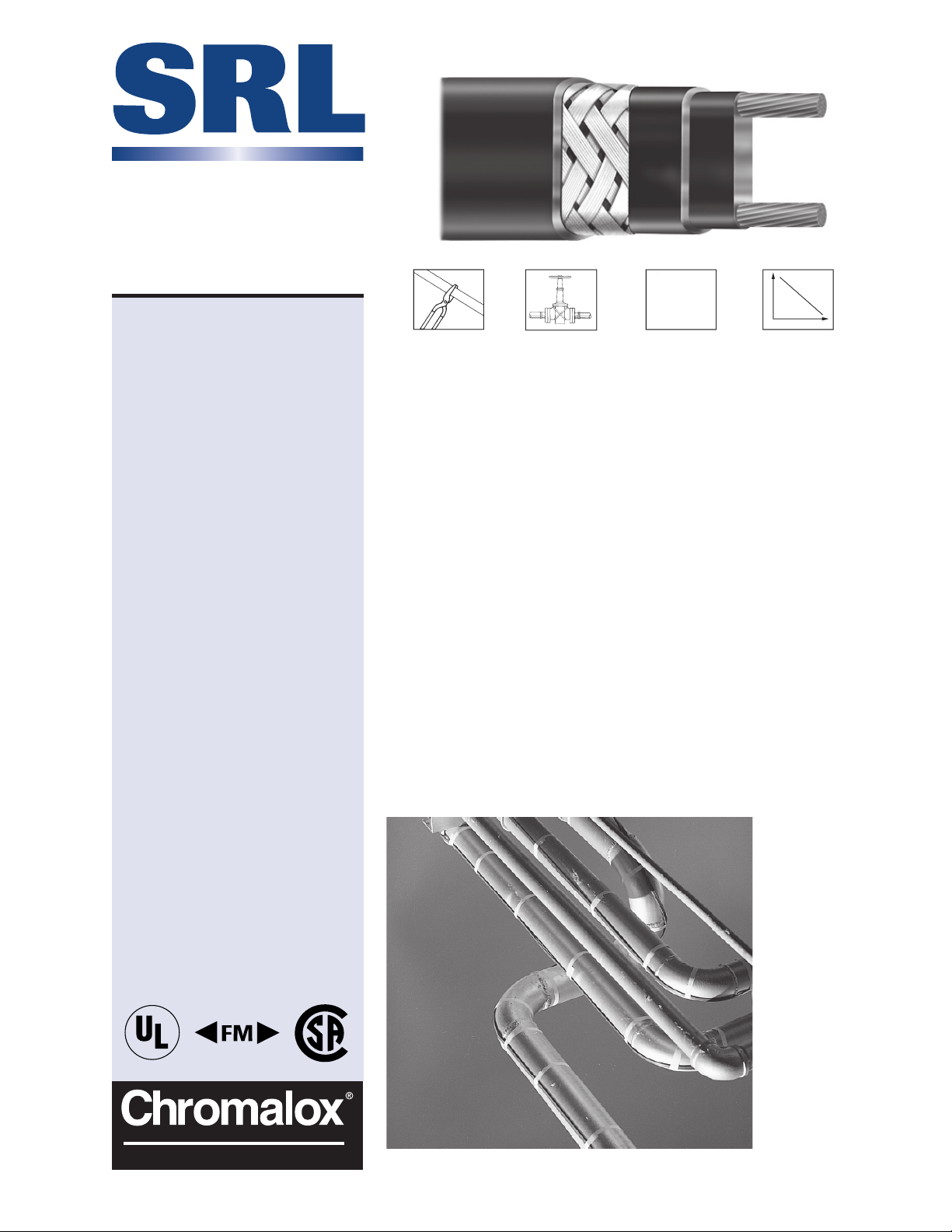
Chromalox SRL self-regulating heating
cable provides safe, reliable heat tracing for freeze protection of pipes,
valves, tanks and similar applications.
Constructed of industrial grade 16
AWG buss wire with a tinned copper
braid and optional overjacketing, SRL
ensures operating integrity in Div. 2
hazardous environments as well as
certain corrosive industrial environments. SRL heating cable has a maximum maintenance temperature rating
of 150°F (65°C).
Features
• Energy efficient, self-regulating SRL
uses less energy when less heat is
required.
• Easy to install, SRL can be cut to
any length (up to maximum circuit
length) in the field.
• Field splices can be performed
easily in minutes with no scrap or
wasted cold sections.
• SRL features lower installed cost
than steam tracing, less maintenance expense, and less downtime.
• SRL can be single overlapped
without burnout, which simplifies
heat tracing of in-line process
equipment such as valves, elbows
and pumps.
• Because SRL is self-regulating,
overtemperature conditions are
virtually impossible.
• Chromalox termination, splice,
tee and end seal kits reduce
installation time.
• UL listed for use on fire protection
System piping
Output
Temperature
• Approximate Size
3/8" x 1/8"
• Minimum Bend Radius is
1-1/8"
®
PRECISION HEAT AND CONTROL
PH: 1-888-996-9258 • FX: 615-793-3563
®
www.chromalox.com
©
2004 Chromalox, Inc.
Page 2
SRL — Self-Regulating Low Temperature Heating Cable
Construction
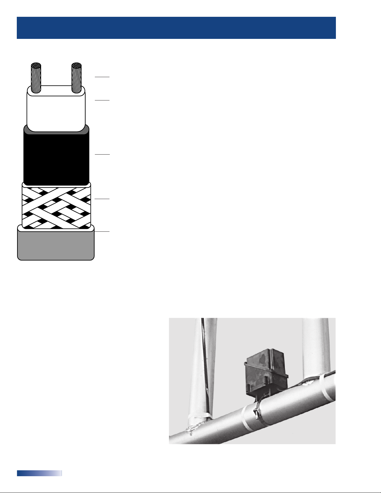
Twin 16 AWG Copper Buss Wires .................. Provide reliable electrical current
capability.
Semiconductive Polymer
Core Matrix ............................................................. “Self-Regulating” component of the
cable, its electrical resistance varies with
temperature. As process temperature
drops, the core’s heat output increases;
as process temperature rises, the heat
output decreases.
Water Resistant
Polyolefin Jacket ................................................... Flame retardant, electrically insulates
the matrix and buss wires and provides
resistance to water and some inorganic
chemical solutions.
Tinned Copper Braid ........................................... Provides additional mechanical protection
in any environment, and a positive
ground path.
High Temperature
Fluoropolymer or TPR Overjacket ................... Corrosion resistant, flame retardant
(Optional) overjacket is highly effective in many
Approvals
FM - Factory Mutual approved for ordinary areas.
UL Listed, CSA Certified for ordinary areas.
UL Listed for fire protection system piping
FM approved for hazardous (classified) areas when
used with Chromalox accessories:
• Class I, Div. 2, Groups B, C, D (gases, vapors)
• Class II, Div. 2, Groups F, G (combustible dust)
• Class III, Div. 2 (easily ignitable fibers and filings)
•3 Watt rated T6 temperature class
•5 and 8 Watt rated T5 temperature class
• 10 Watt rated T4A temperature class
CSA Certified for hazardous (classified) areas when
used with Chromalox accessories:
• Class I, Div. 2, Groups A, B, C, D;
• Class II, Div. 2, Groups F, G
environments. TPR coatings protect
against certain inorganic chemical
solutions. Fluoropolymer coatings are
used for exposure to organic or corrosive
solutions. These coatings also protect
against abrasion and impact damage.
Applications
• Process Temperature Maintenance
• Freeze Protection of Pipes
• Freeze Protection of Fire Protection System Piping
• Fluid Flow and Viscosity Maintenance
®
2
Chromalox
®
• 1382 Heil Quaker Blvd. • LaVergne, TN 37086 • PH:
1-800-443-2640
• FX: 615-793-3563 • www.chromalox.com
Page 3
0
0
30405060
0809010
01
3
01
5
0
t
8
t
5
t
3
t
.
emper
atur
e
p
3
0
3
)
Self-Regulating Low Temperature Heating Cable – SRL
Heating Cable System Design
1. Calculate Heat Loss
Using the Chromalox Design Guide (PJ 304) for Heat Tracing, calculate the heat loss of the system. To calculate the
heat loss (Watts) you will need to know pipe diameter, insulation type and thickness, minimum ambient temperature
and the pipe maintenance temperature.
2. Select Cable Rating
After calculating the heat loss in the pipe and adjusting for any application deviations, you may determine which
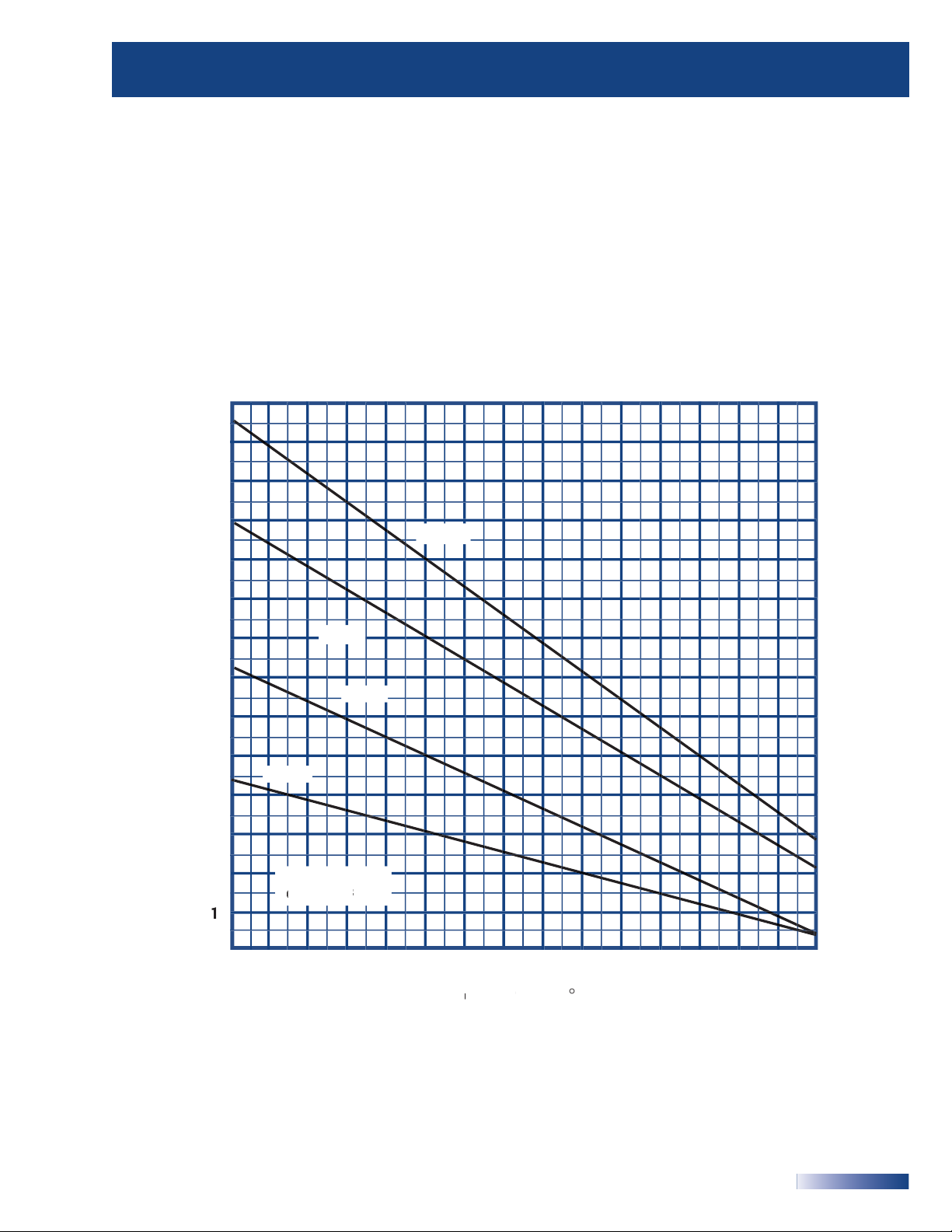
cable rating to choose. Using the SRL Thermal Output Ratings graph, select the lowest cable rating that will provide
the pipe maintenance temperature. Adjust the cable output for line voltage if necessary. See figures from output
wattage at alternative voltages table on page 5.
Thermal Output Ratings On Insulated Metal Pipe
1
1
.)
ut (W
eat Out
W / F
W / F
Cable Output vs
102
W / F
10W / F
7
101201
401
Chromalox
®
• 1382 Heil Quaker Blvd. • LaVergne, TN 37086 • PH:
1-800-443-2640
F
• FX: 615-793-3563 • www.chromalox.com
3
Page 4
SRL — Self-Regulating Low Temperature Heating Cable
3. Determine Total Cable Length
In addition to the system piping, in-line equipment such as valves, flanges and pipe supports require additional heat
tracing to maintain the system operating temperatures.
Total feet of traced pipe + Cable allowance for components = Total cable length
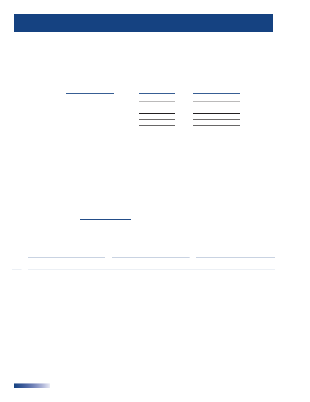
Component Cable Allowances
Component Cable Allowance (Ft.) # of Components Total Additional Cable
Flange Pair 1.5 x =
Pipe Support 2.0 x =
Butterfly Valve 2.5 x =
Ball Valve 2.7 x =
Globe Valve 4.0 x =
Gate Valve 5.0 x =
If spiral wrapping or multiple runs of cable are being used, adjust the allowance by multiplying by the wrapping factor
or the number of runs being used on the pipe.
Guidelines for tracing tanks and vessels are also given in the Chromalox Design Guide (PJ304).
4. Determine Circuits/Circuit Protection
Circuit protection depends on the breaker size being used and the start-up temperature. The National Electric Code
(NEC 1999) requires the use of ground fault protection breakers for heating cable. The following chart shows the
maximum circuit length for a given breaker rating. To determine the number of circuits required for each pipe, divide
the total cable (circuit) length found in Step 3 by the maximum circuit length found in the chart. Round up to the next
higher number.
Number of Circuits = Heater Length
Maximum Circuit Length
Maximum Circuit Length (Ft.) by Start-up Temperature (°F) and Breaker Size (Amps)
50°F Start-Up (Ft.) 0°F Start-Up (Ft.) -20°F Start-Up (Ft.)
Cable Circuit Circuit Circuit
Rating Breaker 10 A 15 A 20 A 25 A 30 A 40 A Breaker 10 A 15 A 20 A 25 A 30 A 40 A Breaker 10 A 15 A 20 A 25 A 30 A 40 A
SRL3-1C 205 305 360 NR NR NR 135 200 270 330 360 NR 120 185 245 300 360 NR
SRL3-2C 400 600 660 NR NR NR 275 415 555 660 NR NR 245 370 495 600 660 NR
SRL5-1C 125 185 250 270 NR NR 90 135 180 225 270 NR 80 120 160 205 245 270
SRL5-2C 250 375 505 540 NR NR 180 270 360 450 540 NR 160 245 325 405 490 540
SRL8-1C 100 150 200 215 NR NR 70 110 145 180 215 NR 65 100 130 165 200 210
SRL8-2C 185 285 375 420 NR NR 135 200 265 335 395 420 120 175 235 300 350 420
SRL10-1C 60 95 130 160 180 NR 50 80 105 130 155 180 45 70 95 120 140 180
SRL10-2C 100 160 210 260 315 360 80 125 170 210 255 340 75 120 160 195 240 320
*Thermal magnetic circuit breakers are recommended since magnetic circuit breakers could “nuisance trip” at low temperature.
NR = Not Required. Maximum circuit length has been reached in a smaller breaker size.
®
4
Chromalox
®
• 1382 Heil Quaker Blvd. • LaVergne, TN 37086 • PH:
1-800-443-2640
• FX: 615-793-3563 • www.chromalox.com
Page 5
Self-Regulating Low Temperature Heating Cable – SRL
Specifications
Cable Ratings Nominal
Output @ 50°F Voltage Maximum Circuit Length*
Model Number (W/Ft.) (Vac) (Ft.)
SRL3-1C 3 120 360
SRL3-2C 3 208-277 660
SRL5-1C 5 120 270
SRL5-2C 5 208-277 540
SRL8-1C 8 120 215
SRL8-2C 8 208-277 420
SRL10-1C 10 120 180
SRL10-2C 10 208-277 360
*See chart on page 4 for maximum circuit lengths by start-up temperature and circuit breaker size
Output Wattage at Alternate Voltages (50°F) W/Ft.
% Change % Change % Change
Cable Rating 208 Volts In Output 220 Volts In Output 277 Volts In Output
SRL3 2.4 -20 2.6 -13 3.4 +15
SRL5 4.1 -18 4.5 -10 5.6 +13
SRL8 6.88 -14 7.28 -9 8.96 +12
SRL10 8.7 -13 9.2 -8 11.1 +10
Ordering Information
Output Voltage Model
(W/Ft.) (Vac) Number PCN
3 120 SRL3 - 1C 382678
SRL3 - 1CR 382731
SRL3 - 1CT 383400
208-277 SRL3 - 2C 382686
SRL3 - 2CR 382740
SRL3 - 2CT 383419
5 120 SRL5 - 1C 382694
SRL5 - 1CR 382758
SRL5 - 1CT 383443
208-277 SRL5 - 2C 382707
SRL5 - 2CR 382766
SRL5 - 2CT 383451
Output Voltage Model
(W/Ft.) (Vac) Number PCN
8 120 SRL8 - 1C 382555
SRL8 - 1CR 382598
SRL8 - 1CT 383460
208-277 SRL8 - 2C 382563
SRL8 - 2CR 382600
SRL8 - 2CT 383478
10 120 SRL10 - 1C 382820
SRL10 - 1CR 382846
SRL10 - 1CT 383486
208-277 SRL10 - 2C 382838
SRL10 - 2CR 382854
SRL10 - 2CT 383494
To Order: Specify length, Model Number, PCN and Installation Accessories.
Chromalox
®
• 1382 Heil Quaker Blvd. • LaVergne, TN 37086 • PH:
1-800-443-2640
• FX: 615-793-3563 • www.chromalox.com
5
Page 6
SRL — Self-Regulating Low Temperature Heating Cable
Model Numbers
SRL 5 - 1 C T
Overcoat Options
T = Fluoropolymer corrosion resistant
overjacket over braid for hostile/
corrosive environments
R = TPR overjacket over braid for
protection against certain inorganic
chemical solutions
Braid
C = Standard tinned-copper metallic braid for ground path
Voltage
1 = 120 Volts
2 = 208-277 Volts
Output (watts)
3, 5, 8, 10 Watts per Foot
SRL
Self-Regulating, Low Temperature Heating Cable
Accessories
Chromalox has a complete line of accessories specifically designed for use with SRL cable. Use only Chromalox
accessories to ensure the performance of the heat trace system.
Model Description
Thermostat RTAS DL Series air-sensing thermostat with Microswitch
for local control of circuit.
RTBC DL Series pipewall-sensing thermostat with Microswitch
for local control of circuit.
Power Connection RTPC DL Series power connection set kit.
RTST DL Series splice and tee set kit.
RTES DL Series end seal kit.
Pipe Straps PS-1, PS-3, PS-10 Pipe straps to affix thermostat and power connection splice kits to
pipes.
Fiberglass Tape FT-2 Tape to affix cable to pipe, 66' x 1/2" roll, install on 12" centers.
Aluminum Tape AT-1 Tape to aid heat transfer, 180 foot roll.
Apply over cable along entire length of circuit.
®
®
Caution Labels CL-1 “Electrical Heat Tracing” caution labels, 5 per package.
Install every 10 feet.
Control Panels Contact your Chromalox representative for Control Panel information.
Note - For PCN's, refer to the DL Series connection system accessories product data sheet.
®
6
Chromalox
®
• 1382 Heil Quaker Blvd. • LaVergne, TN 37086 • PH:
1-800-443-2640
• FX: 615-793-3563 • www.chromalox.com
PJ320-2
PDS SRL
APRIL 04
 Loading...