

Page 1
5
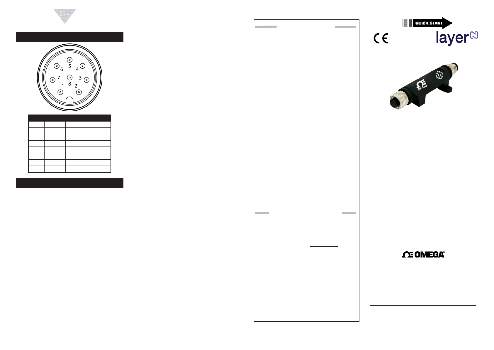
Layer N Digital Connector Diagram
Name Funcon
Pin 1 DIO 0
Pin 2 INTR
Pin 3
Pin 4
Pin 5
Pin 6 DIO 1
Pin 7
Pin 8 3.3VDD
Specicaons
INPUT POWER
Voltage: 2.8 VDC - 3.3 V
DIO DIGITAL INPUTS
V
V
V
DIO DIGITAL OUTPUTS
inHighThreshold
inLowThreshold
= 30 V
inMAX
= 2.2 V
= 0.3 V
DC
2x Open Drain 100 mA max
V
ENVIRONMENTAL
MAX
= 30 V
DC
Operang Temperature: -40 to 85C (-40 to 185
Rating: IP67 when mated
MECHANICAL
Dimensions:
not including mounting tabs
GENERAL
Agency Approvals: CE, EMC 2014/30/EU,
LVD 2014/35/EU
Conguraon:
Soware:
DC
MAX
MIN
OMEGA ENGINEERING, INC. warrants this unit to be free of defects
WARRANTY/DISCLAIMER
in materials and workmanship for a period of 13 months from
date of purchase. OMEGA’s WARRANTY adds an additional one (1)
month grace period to the normal one (1) year product warranty
to cover handling and shipping time. This ensures that OMEGA’s
customers receive maximum coverage on each product.
If the unit malfunctions, it must be returned to the factory for evaluation. OMEGA’s Customer Service Department will issue an Authorized
Return (AR) number immediately upon phone or written request.
Upon examination by OMEGA, if the unit is found to be defective,
it will be repaired or replaced at no charge. OMEGA’s WARRANTY
does not apply to defects resulting from any action of the purchaser,
including but not limited to mishandling, improper interfacing, operation outside of design limits, improper repair, or unauthorized modification. This WARRANTY is VOID if the unit shows evidence of having
been tampered with or shows evidence of having been damaged as a
result of excessive corrosion; or current, heat, moisture or vibration;
improper specification; misapplication; misuse or other operating
conditions outside of OMEGA’s control. Components in which wear
is not warranted, include but are not limited to contact points, fuses,
and triacs.
OMEGA is pleased to offer suggestions on the use of its various products. However, OMEGA neither assumes responsibility for any omissions or errors nor assumes liability for any
damages that result from the use if its products in accordance
with information provided by OMEGA, either verbal or written. OMEGA warrants only that the parts manufactured by
the company will be as specified and free of defects. OMEGA
MAKES NO OTHER WARRANTIES OR REPRESENTATIONS OF
ANY KIND WHATSOEVER, EXPRESSED OR IMPLIED, EXCEPT
THAT OF TITLE, AND ALL IMPLIED WARRANTIES INCLUDING
ANY WARRANTY OF MERCHANTABILITY AND FITNESS
FOR A PARTICULAR PURPOSE ARE HEREBY DISCLAIMED.
LIMITATION OF LIABILITY: The remedies of purchaser set
forth herein are exclusive, and the total liability of OMEGA
with respect to this order, whether based on contract, warranty, negligence, indemnification, strict liability or otherwise,
shall not exceed the purchase price of the component upon
which liability is based. In no event shall OMEGA be liable for
consequential, incidental or special damages.
CONDITIONS: Equipment sold by OMEGA is not intended to be used,
nor shall it be used: (1) as a “Basic Component” under 10 CFR 21 (NRC),
used in or with any nuclear installation or activity; or (2) in medical applications or used on humans. Should any Product(s) be used in or with
any nuclear installation or activity, medical application, used on humans,
or misused in any way, OMEGA assumes no responsibility as set forth
in our basic WARRANTY/DISCLAIMER language, and, additionally,
purchaser will indemnify OMEGA and hold OMEGA harmless from any
liability or damage whatsoever arising out of the use of the Product(s)
in such a manner.
RETURN REQUESTS/INQUIRIES
Direct all warranty and repair requests/inquiries to the OMEGA
Customer Service Department. BEFORE RETURNING ANY
PRODUCT(S) TO OMEGA, PURCHASER MUST OBTAIN AN
AUTHORIZED RETURN (AR) NUMBER FROM OMEGA’S CUSTOMER
SERVICE DEPARTMENT (IN ORDER TO AVOID PROCESSING
DELAYS). The assigned AR number should then be marked on the
outside of the return package and on any correspondence.
FOR WARRANTY RETURNS,
please have the following
information available BEFORE
contacting OMEGA:
1. Purchase Order number
under which the product
was PURCHASED,
2. Model and serial number of the
product under warranty, and
3. Repair instructions and/or
specific problems relative
to the product.
OMEGA’s policy is to make running changes, not model changes,
whenever an improvement is possible. This affords our customers
the latest in technology and engineering.
OMEGA is a trademark of OMEGA ENGINEERING, INC.
© Copyright 2019 OMEGA ENGINEERING, INC. All rights reserved.
This document may not be copied, photocopied, reproduced,
translated, or reduced to any electronic medium or machine-readable
form, in whole or in part, without the prior written consent of OMEGA
ENGINEERING, INC.
MQS5818/0320
FOR NON-WARRANTY REPAIRS,
consult OMEGA for current repair
charges. Have the following
information available BEFORE
contacting OMEGA:
1. Purchase Order number to cover
the COST of the repair or
calibration,
2. Model and serial number of the
product, and
3. Repair instructions and/or specific
problems relative to the product.
SP-010
Layer N Load Cell Smart Probe
omega.com [email protected]
U.S.A. Omega Engineering, Inc.
Headquarters: 800 Connecticut Ave. Suite 5N01, Norwalk, CT 06854
Toll-Free: 1-800-826-6342 (USA & Canada only)
Customer Service: 1-800-622-2378 (USA & Canada only)
Engineering Service: 1-800-872-9436 (USA & Canada only)
Tel: (203) 359-1660 Fax: (203) 359-7700
e-mail: [email protected]
For Other Locations Visit omega.com/worldwide
The information contained in this document is believed to be correct, but
OMEGA accepts no liability for any errors it contains, and reserves the right to
alter specifications without notice.
Servicing North America:
Page 2
START HERE
2
3
4
Introducon
Materials
Included with your SP-010
Addional Materials Needed
• 4-Wire Bridge sensor
Oponal Materials
Before you Begin
met:
•
•
Connecng your Strain Bridge
Note:
Connecng your Smart Probe & Interface
Step 1:
Note:
Step 2:
SYNC Auto-Detect
readings.
Note:
Conguring Load Cell.
SYNC Manual Connecon
steps:
Step 1:
Step 2: and click Next.
Conguring Load Cell
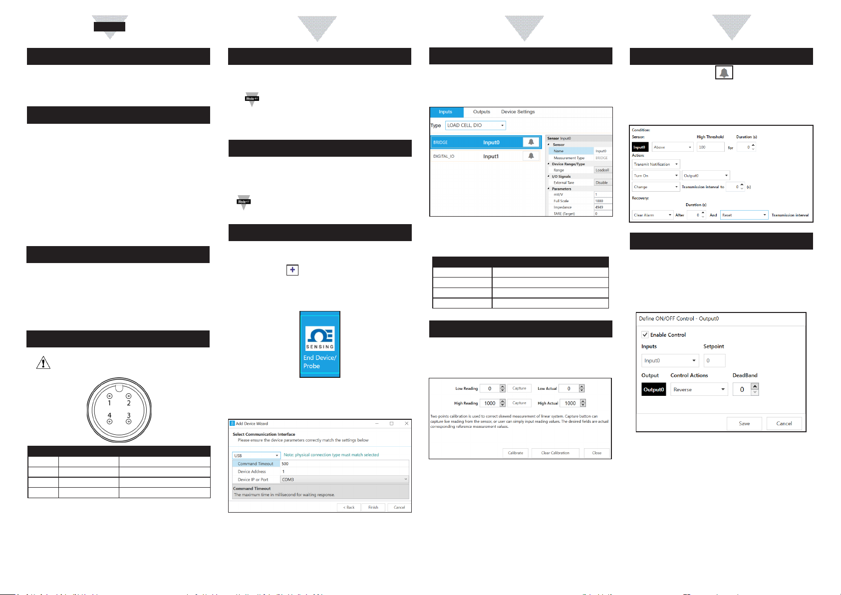
Step 1: Click the Inputs Conguraon Tab
the Load CellType drop down.
Parameters
Parameter Descripon
mV/V
Bridge Maximum load
Impedance Bridge Impedance
Update this parameter to TARE bridge
2-Point Calibraon
Step 1:Load Cell Input
Calibrate.
Seng Alarms
Inputs
Condion
select which output to turn on in the Acon
can be set to be latching or non-latching in the Recovery
ON/OFF Control
Output Conguraon Tab
the Dene ON/OFF Control dialog box as seen below. Choose
Name Funcon
Pin 1 Exc -
Pin 2 Bridge Output
Pin 3 Bridge Output
Pin 4
Step 3:Communicaon Interface
Step 4: Click Finish.
Step 2:Capture next to
Low Reading.
Low Actual Box.
Step 3:Capture next to
Low Reading.
weight in the High Actual Box.
Step 4:
The Setpoint
Deadband
When Reverse control is selected, the output is on when the
Setpoint. When Direct control is
Setpoint
 Loading...