

Page 1
Specications
Inputs:
Ranges:eldcongurable,seeTable6
Impedance:>1MOhms
InputBiasCurrent(burnoutdetection):
<1.5 microamp
Overvoltage:±10Vdifferential
CommonMode(InputtoGround):
1500VDCorpeakAC,max
ZeroandSpanRange:
ZeroTurn-Up:
0to50%offullscalerange
SpanTurn-Down:
100to50%offullscalerange
Outputs:
VoltageOutput:eld-congurable
Ranges:0-5V,0-10V
Impedance:<10Ohms
Drive:10mA,max.(1KOhms,min.)
CurrentOutput:eld-congurable
Ranges:0-1mA,4-20mA
Impedance:>100KOhms
Compliance:10V,max.(500Ohms,max.
@20mA)
Pin Connections
1 Power (Hot)
2 No Connection
3 Power (Neu)
4 Do not use
5 Input (+)
6 Input (-)
7 Output (+)
8 Output (-)
OMEGA ENGINEERING, INC., warrants this unit to be free of defects in materials and workmanship for a period of 13 months from date of purchase.
omega.com info@omega.
Servicing North America:
U.S.A.:
Omega Engineering, Inc., One Omega Drive,
P.O. Box 4047, Stamford, CT 06907-0047 USA
Toll-Free: 1-800-826-6342 (USA & Canada only)
Customer Service: 1-800-622-2378
(USA & Canada only)
Engineering Service: 1-800-872-9436
(USA & Canada only)
Tel: (203) 359-1660
Fax: (203) 359-7700
e-mail: info @omega.com
For Other Locations Visit
omega.com/worldwide
The information contained in this document is
believed to be correct, but OMEGA accepts no
liability for any errors it contains, and reserves
the right to alter specifications without notice.
com
OMEGA’s WARRANTY adds an additional one (1) month grace period to the normal one (1) year product warranty to cover handling and shipping
time. This ensures that OMEGA’s customers receive maximum coverage on each product.
If the unit malfunctions, it must be returned to the factory for evaluation. OMEGA’s Customer Service Department will issue an Authorized Return
(AR) number immediately upon phone or written request. Upon examination by OMEGA, if the unit is found to be defective, it will be repaired
or replaced at no charge. OMEGA’s WARRANTY does not apply to defects resulting from any action of the purchaser, including but not limited to
mishandling, improper interfacing, operation outside of design limits, improper repair, or unauthorized modification. This WARRANTY is VOID if
the unit shows evidence of having been tampered with or shows evidence of having been damaged as a result of excessive corrosion; or current,
heat, moisture or vibration; improper specification; misapplication; misuse or other operating conditions outside of OMEGA’s control. Components
in which wear is not warranted, include but are not limited to contact points, fuses, and triacs.
OMEGA is pleased to offer suggestions on the use of its various products. However, OMEGA neither assumes responsibility for any omissions
or errors nor assumes liability for any damages that result from the use of its products in accordance with information provided by OMEGA,
either verbal or written. OMEGA warrants only that the parts manufactured by the company will be as specified and free of defects. OMEGA
MAKES NO OTHER WARRANTIES OR REPRESENTATIONS OF ANY KIND WHATSOEVER, EXPRESSED OR IMPLIED, EXCEPT THAT OF TITLE, AND
ALL IMPLIED WARRANTIES INCLUDING ANY WARRANTY OF MERCHANTABILITY AND FITNESS FOR A PARTICULAR PURPOSE ARE HEREBY
DISCLAIMED. LIMITATION OF LIABILITY: The remedies of purchaser set forth herein are exclusive, and the total liability of OMEGA with respect to
this order, whether based on contract, warranty, negligence, indemnification, strict liability or otherwise, shall not exceed the purchase price of
the component upon which liability is based. In no event shall OMEGA be liable for consequential, incidental or special damages.
CONDITIONS: Equipment sold by OMEGA is not intended to be used, nor shall it be used: (1) as a “Basic Component” under 10 CFR 21 (NRC), used
in or with any nuclear installation or activity; or (2) in medical applications or used on humans. Should any Product(s) be used in or with any nuclear
installation or activity, medical application, used on humans, or misused in any way, OMEGA assumes no responsibility as set forth in our basic
WARRANTY/DISCLAIMER language, and, additionally, purchaser will indemnify OMEGA and hold OMEGA harmless from any liability or damage
whatsoever arising out of the use of the Product(s) in such a manner.
Direct all warranty and repair requests/inquiries to the OMEGA Customer Service Department. BEFORE RETURNING ANY PRODUCT(S) TO OMEGA,
PURCHASER MUST OBTAIN AN AUTHORIZED RETURN (AR) NUMBER FROM OMEGA’S CUSTOMER SERVICE DEPARTMENT (IN ORDER TO AVOID
PROCESSING DELAYS). The assigned AR number should then be marked on the outside of the return package and on any correspondence.
The purchaser is responsible for shipping charges, freight, insurance and proper packaging to prevent breakage in transit.
FOR WARRANTY RETURNS, please have the following
information available BEFORE contacting OMEGA.
1. Purchase order number which the product was PURCHASED,
2. Model and serial number of the product under warranty, and
3. Repair instructions and/or specific problems relative to
the product.
OMEGA’s policy is to make running changes, not model changes, whenever an improvement is possible. This affords custo mers the late st
technology and engineering. OMEGA is a registered trademark of OMEGA ENGINEERING, INC.
© COPYRIGHT 2015 OMEGA ENGINEERING, INC. All rights reserved. This document may not be copied, photocopied, translated, or reduced to
any electronic medium-readable form, in whole or in part, without the prior written consent of OMEGA ENGINEERING, INC.
Accuracy (Including Linearity, Hysteresis):
seeTable5
Response Time(10-90%):
500mSec,typical
Stability:
±0.04%/°Coffullscalerange
Isolation:
1500VDCorpeakACbetweeninput,
outputandpower
ESD Susceptibility:
MeetsIEC801- 2,Level2(4KV)
Common Mode Rejection:
DC-60Hz:120dB
LED Indicators:
TROUBLELED:Yellow-offduring
normaldeviceoperation
INPUTLED:Green-continuouslyonif
inputiswithinselectedrange,ashes
otherwise
CALOKLED:Yellow-continuouslyonin
normaldeviceoperation
Thermocouple Burnout Detect:
Field-congurableUporDownscale,or
disabled
WARRANTY/DISCLAIMER
RETURN REQUESTS/INQUIRIES
FOR NON-WARRANTY RETURNS, consult OMEGA for current repair
charges. Have the following information available BEFORE contacting
OMEGA.
1. Purchase Order number to cover the COST of the repair,
2. Model and serial number of the product and
3. Repair instructions and/or specific problems relative to the product.
Humidity (Non-Condensing):
Operating:25to95%(@45°C)
Soak:90%for24Hrs.(@65°C)
Temperature Range:
Operating:0to60°C(32to140°F)
Storage:-15to75°C(5to167°F)
Power:
Consumption:3Wtypical,5Wmax
Standard:120VAC±10%,50-60Hz
Optional:240VAC
Weight:
0.62lbs
Approvals:
ULrecognizedperstandardUL508.
(FileNo.E99775).
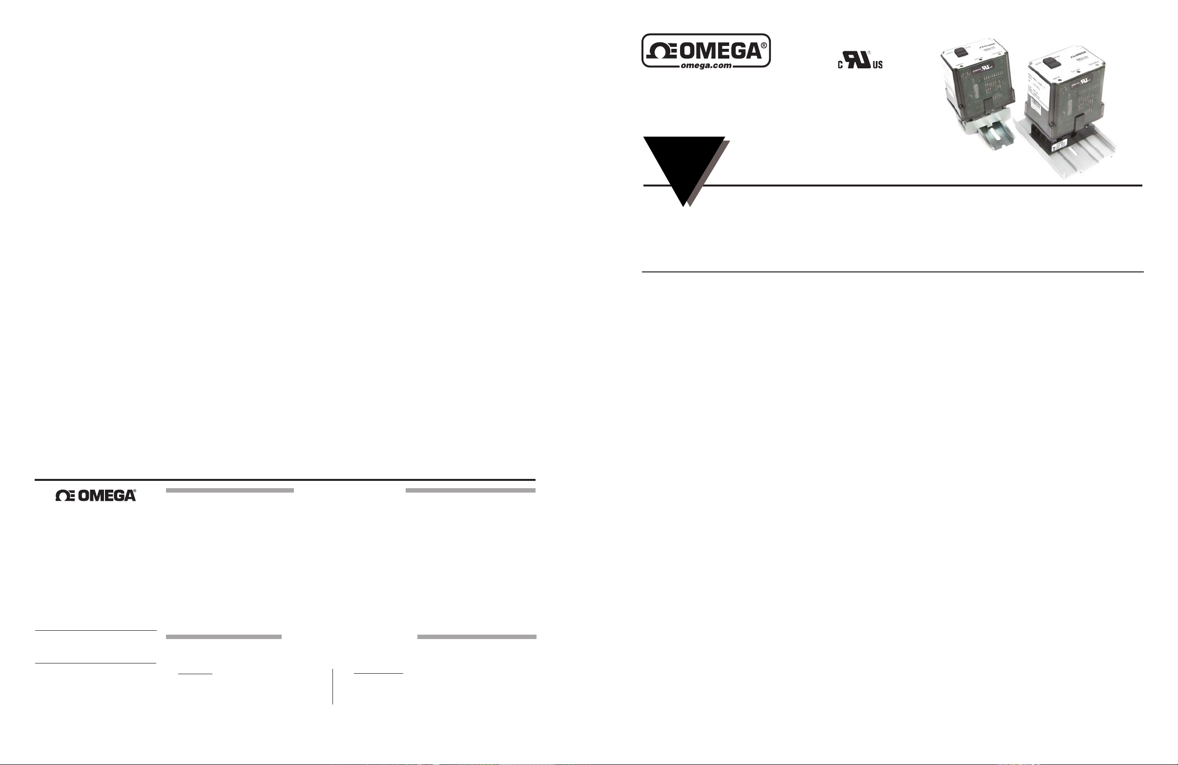
SMSC-TC
Thermocouple Input, Field Configurable
Signal Conditioner
INSTRUCTION
SHEET
Shop online at omega.comSM e-mail: [email protected]
For latest product manuals: www.omegamanual.info
FieldCongurableThermocoupleTypes
LinearizedOutputs
Wide-RangingZeroandSpanAdjustability(50%)
Description
TheSMSC-TC isolatingthermocoupleconditionerofferswide
ranging input and output capability. The SMSC-TC can be
eldconguredbytheusertoacceptinputfromthermocouple
typesJ,K,T,R,S,E,andBandtoprovidecurrentorvoltage
output.Theoutputislinearizedtotemperatureaccordingtothe
particularthermocoupletype.
TheSMSC-TCisathree-portindustrialisolator—theoutput
isopticallyisolatedfromtheinputupto1500V,andbothinput
andoutputaretransformerisolatedfromthelinepower.Isolation
allowsthenoisereductionbenetsofgroundedthermocouples
to be realized without creating ground loop problems and it
providesfasterresponse.TheSMSC-TC utilizes the latest in
advancedanalog/digital signal processing technology.Inadditiontoitsmultiplemicroprocessors,itemploysspecialASIC
circuitryforhighaccuracyandreliability.
The SMSC-TC is equipped with cold-junction compensation
(CJC)circuitry to provide ice-pointreference.Upscale,downscale or disabled thermocouple burnout detection is switch
selectable.
Application
TheAP4351isusefulinanyapplicationrequiringanisolatedDC
outputfromathermocoupleinput.Typicalapplicationsinclude
energymanagementanddataacquisitionofprocesstemperatures.TheoutputoftheSMSC-TCcandriveadigitalmeterfor
directdisplayorinterfacewithacomputerformonitoringand
controlapplications.
Status LEDs
ModelSMSC-TCisequippedwithtop-mountedLEDsforINPUT
(green),TROUBLE(yellow)andCALOK(yellow).Atstart-up,
boththe INPUT andthe CAL OK LEDs lightup momentarily
for1second.Afterwards, these LEDs ash alternatelyfor10
secondswhilestart-uptakesplace.
Input LED
Thisinput LEDisadiagnostictool.It remainscontinuouslylit
if the measured temperature is within the selected range of
the thermocouple. However, if the measured temperature is
M5483/0715
ProvidesIsolated,LinearizedDCOutput
inProportiontoThermocoupleInput
EliminatesGroundLoops
ThermocoupleBurnoutDetection
ASICTechnologyforEnhancedReliability
outsidethe full range ofthethermocouple(forexample,fora
typeJ-belowminus200°Corabove750°C),theLEDwillash
ata rate of 4or 8Hz for under/overrange, repectively. If the
thermocoupleiswithinthefulltemperaturerange,butoutside
theselectedsub-range(forexample,ifatypeJthermocouple
issetforrange13andthetemperatureiseitherbelow375°C
orabove500°C)theLEDwillashat0.5or1Hzrespectively.
Cal OK LED
ThisLEDiscontinuouslyonwhenthedeviceisproperlystoring
thefactorycalibrationreferencevoltage.
Trouble LED
ThisLEDisoffduringnormaloperationofthedevice.IfthisLED
isoncontactAction'sTechnicalServicesGroup.
Options
U Urethanecoatingofinternalcircuitryforprotectionfrom
corrosiveatmospheres.
C620 Factorycalibration(specify
inputthermocoupletype,temperaturerangeandoutput).
Conguration
AmajoradvantageoftheSMSC-TCisitswiderangingcapabilitiesandeaseofconguration.TheSMSC-TCenables50%
inputzeroandspanadjustabilitywithintheselectedsub-range.
Forexample,range#5foranE-TypethermocoupleinTable6
species-18°Cto125°C.Sincethespancanbecontractedby
50%,thisenablesaninputspanasnarrowas50%of143°C,
or72°C.Thisspancanthenbepositionedanywherewithinthe
temperaturerange and can have a zero step-upas large as
50%ofthefullscalerange(e.g.spancanstartashighas53°C).
Unless otherwise specied, the factory pre-sets the Model
SMSC-TCasfollows:
Input: J-type
Range: 0-500°C
Output: 4-20mA
BurnOut: Upscale
Page 2
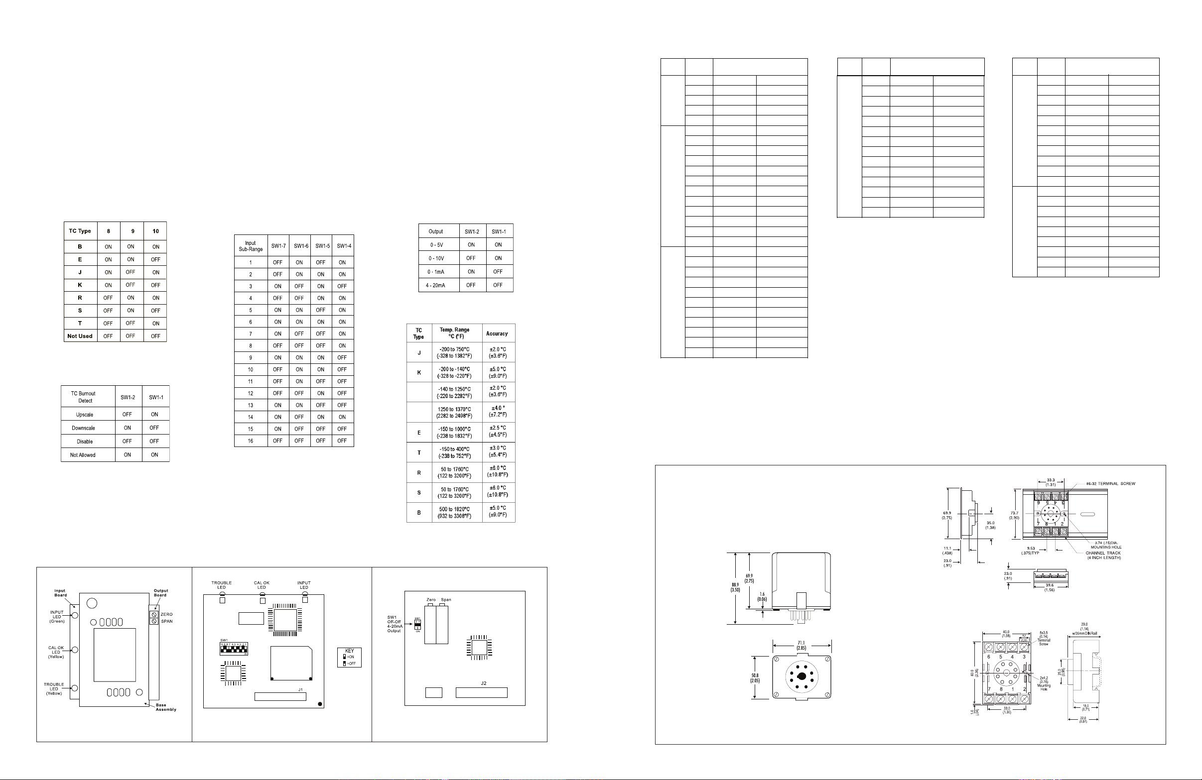
For other settings, remove the four base screws and
TC Type
Range
Number
Temperature Range
B
6 500 to 1820°C (932to 3308°F)
7 1000 to 1820°C (1832 to 3308°F)
8 500 to 1000°C (932 to 1832°F)
11 1500 to 1820°C (2732 to 3308°F)
12 750 to 1000°C (1382 to 1832°F)
E
2 -18 to 1000°C (0 to 1832°F)
3 -18 to 500°C (0 to 932°F)
4 -18 to 250°C (0 to 482°F)
5 -18 to 125°C (0 to 257°F)
8 500 to 1000°C (932 to 1832°F)
9 250 to 500°C (482 to 932°F)
10 125 to 250°C (257 to 482°F)
12 750 to 1000°C (1382 to 1832°F)
13 375 to 500° C (707 to 932°F)
14 -150 to 750°C (-238 to 1382°F)
15 -150 to 250°C (-238 to 482°F)
16 -150 to 0°C (-238 to 32°F)
J
2 -18 to 750°C (0 to 1382°F)
3 -18 to 500°C (0 to 932°F)
4 -18 to 250°C (0 to 482°F)
5 -18 to 125°C (0 to 257°F)
8 500 to 750°C (932 to 1382°F)
9 250 to 500°C (482 to 932°F)
10 125 to 250°C (257 to 482°F)
13 375 to 500°C (707 to 932°F)
14 -200 to 750°C (-328to 1382°F)
15 -200 to 250°C (-328 to 482°F)
16 -200 to 0°C (-328 to 32°F)
TC Type
Range
Number
Temperature Range
TC Type
Range
Number
Temperature Range
B
6 500 to 1820°C (932to 3308°F)
7 1000 to 1820°C (1832 to 3308°F)
8 500 to 1000°C (932 to 1832°F)
11 1500 to 1820°C (2732 to 3308°F)
12 750 to 1000°C (1382 to 1832°F)
E
2 -18 to 1000°C (0 to 1832°F)
3 -18 to 500°C (0 to 932°F)
4 -18 to 250°C (0 to 482°F)
5 -18 to 125°C (0 to 257°F)
8 500 to 1000°C (932 to 1832°F)
9 250 to 500°C (482 to 932°F)
10 125 to 250°C (257 to 482°F)
12 750 to 1000°C (1382 to 1832°F)
13 375 to 500° C (707 to 932°F)
14 -150 to 750°C (-238 to 1382°F)
15 -150 to 250°C (-238 to 482°F)
16 -150 to 0°C (-238 to 32°F)
J
2 -18 to 750°C (0 to 1382°F)
3 -18 to 500°C (0 to 932°F)
4 -18 to 250°C (0 to 482°F)
5 -18 to 125°C (0 to 257°F)
8 500 to 750°C (932 to 1382°F)
9 250 to 500°C (482 to 932°F)
10 125 to 250°C (257 to 482°F)
13 375 to 500°C (707 to 932°F)
14 -200 to 750°C (-328to 1382°F)
15 -200 to 250°C (-328 to 482°F)
16 -200 to 0°C (-328 to 32°F)
K
1 -18 to 1370°C (0 to 2498°F)
2 -18 to 1000°C (0 to 1832°F)
3 -18 to 500°C (0 to 932°F)
4 -18 to 250°C (0 to 482°F)
5 -18 to 125°C (0 to 257°F)
7 1000 to 1370°C (1832 to 2498°F)
8 500 to 1000°C (932 to 1832°F)
9 250 to 500°C (482 to 932°F)
10 125 to 250°C (257 to 482°F)
12 750 to 1000°C (1382 to 1832°F)
13 375 to 500°C (707 to 932°F)
14 -200 to 750°C (-328 to 1382°F)
15 -200 to 250°C (-328 to 482°F)
16 -200 to 0°C (-328 to 32°F)
TC Type
Range
Number
Temperature Range
B
6 500 to 1820°C (932to 3308°F)
7 1000 to 1820°C (1832 to 3308°F)
8 500 to 1000°C (932 to 1832°F)
11 1500 to 1820°C (2732 to 3308°F)
12 750 to 1000°C (1382 to 1832°F)
E
2 -18 to 1000°C (0 to 1832°F)
3 -18 to 500°C (0 to 932°F)
4 -18 to 250°C (0 to 482°F)
5 -18 to 125°C (0 to 257°F)
8 500 to 1000°C (932 to 1832°F)
9 250 to 500°C (482 to 932°F)
10 125 to 250°C (257 to 482°F)
12 750 to 1000°C (1382 to 1832°F)
13 375 to 500° C (707 to 932°F)
14 -150 to 750°C (-238 to 1382°F)
15 -150 to 250°C (-238 to 482°F)
16 -150 to 0°C (-238 to 32°F)
J
2 -18 to 750°C (0 to 1382°F)
3 -18 to 500°C (0 to 932°F)
4 -18 to 250°C (0 to 482°F)
5 -18 to 125°C (0 to 257°F)
8 500 to 750°C (932 to 1382°F)
9 250 to 500°C (482 to 932°F)
10 125 to 250°C (257 to 482°F)
13 375 to 500°C (707 to 932°F)
14 -200 to 750°C (-328to 1382°F)
15 -200 to 250°C (-328 to 482°F)
16 -200 to 0°C (-328 to 32°F)
K
1 -18 to 1370°C (0 to 2498°F)
2 -18 to 1000°C (0 to 1832°F)
3 -18 to 500°C (0 to 932°F)
4 -18 to 250°C (0 to 482°F)
5 -18 to 125°C (0 to 257°F)
7 1000 to 1370°C (1832 to 2498°F)
8 500 to 1000°C (932 to 1832°F)
9 250 to 500°C (482 to 932°F)
10 125 to 250°C (257 to 482°F)
12 750 to 1000°C (1382 to 1832°F)
13 375 to 500°C (707 to 932°F)
14 -200 to 750°C (-328 to 1382°F)
15 -200 to 250°C (-328 to 482°F)
16 -200 to 0°C (-328 to 32°F)
TC Type
Range
Number
Temperature Range
polycarbonatecasetoaccessthecongurationswitches.
2.Setthecalibratortothedesiredminimuminputandadjustthe
zeropotentiometerforthedesiredminimumoutput.
Table6:ThermocoupleRangeSettings
Referto Tables 1through 6 and Figures 1through 3 forthe
properswitchlocationsandsettings.Usingtheswitch on the
inputboardselectthermocoupletype,temperaturerange,and
thermocoupleburnoutdetection.Usingtheswitchontheoutput
board,selectdesiredtypeofoutput.Replacethecasepriorto
applyingpowertotheunit.
Calibration
1.Connecttheinputtoacalibratedthermocouplesourceand
applypower.Wait1-2hoursforthermalstabilitybeforemonitoring
thevoltage/currentoutput.RefertoPINCONNECTIONS.
Table2:Thermocoupleburnoutdetection
switchsettings
(SW1onInputBoard)
Figure1:TopView
Figure2:InputBoard Figure3:OutputBoard
3.Setthecalibratortothedesiredmaximuminputandadjust
thespanpotentiometerforthedesiredmaximumoutput.
4.Repeatsteps2and3,asnecessary,forbestaccuracy.
Table4:Outputswitchsettings
(SW1onOutputBoard)
Table5:SMSC-TCAccuracy
Mounting
Allmodulesfeatureplug-ininstallation.ModelSMSC-TCusesan
8-pinbaseandmolded-socketsSKT-SM-8P,orDIN-socketSKT-DR-8P.
Dimensions
Dimensionsareinmillimeters(inches)
Mark III
1 50 to 1760°C (122 to 3200°F)
2 50 to 1000°C (122 to 1832°F)
3 50 to 500°C (122 to 932°F)
4 50 to 250°C (122 to 482°F)
7 1000 to 1760°C (1832 to 3200°F)
R, S
8 500 to 1000°C (932 to 1832°F)
9 250 to 500°C (482 to 932°F)
10 125 to 250°C (257 to 482°F)
11 1500 to 1760°C (2732 to 3200°F)
12 750 to 1000°C (1382 to 1832°F)
13 375 to 500°C (707 to 932°F)
3 -18 to 400°C (0 to 752°F)
4 -18 to 250°C (0 to 482°F)
5 -18 to 125°C (0 to 257°F)
9 250 to 400°C (482 to 752°F)
T
10 125 to 250°C (257 to 482°F)
13 375 to 400°C (707 to 752°F)
14 -150 to 400°C (-238 to 752°F)
15 -150 to 250°C (-238 to 482°F)
16 -150 to 0°C (-238 to 32°F)
SKT-SM-8P (Track/Surface)
SKT-DR-8P (DIN Rail)
 Loading...