

Page 1
Specications
Input:
VoltageInput(eldcongurable)
FullScaleRange:
10mV to 100V
Impedance:>100KOhms
Overvoltage:
Intermittent,400Vrms
Continous,264Vrms
CurrentInput(eldcongurable)
FullScaleRange:1mAto100mA
Impedance:20Ohms,typical
Overcurrent:170mARMS,max
Overvoltage:60VDC
CommonMode(InputtoGround):
1500VDC,max
ZeroTurn-Up:
50%offullscalerange
SpanTurn-Down:
50%offullscalerange
Pin Connections
1 Power(Hot)
2 NotInternallyConnected
3 Power(Neu)
4 SpareTermination
5 Input(+)
6 Input(-)
7 Output(+)
8 Output(-)
DCPower:PIN1=(+);PIN3=(-)
OMEGA ENGINEERING, INC., warrants this unit to be free of defects in materials and workmanship for a period of 13 months from date of purchase.
omega.com info@omega.
com
Servicing North America:
U.S.A.:
Omega Engineering, Inc., One Omega Drive,
P.O. Box 4047, Stamford, CT 06907-0047 USA
Toll-Free: 1-800-826-6342 (USA & Canada only)
Customer Service: 1-800-622-2378
(USA & Canada only)
Engineering Service: 1-800-872-9436
(USA & Canada only)
Tel: (203) 359-1660
Fax: (203) 359-7700
e-mail: info @omega.com
For Other Locations Visit
omega.com/worldwide
The information contained in this document is
believed to be correct, but OMEGA accepts no
liability for any errors it contains, and reserves
the right to alter specifications without notice.
OMEGA’s WARRANTY adds an additional one (1) month grace period to the normal one (1) year product warranty to cover handling and shipping
time. This ensures that OMEGA’s customers receive maximum coverage on each product.
If the unit malfunctions, it must be returned to the factory for evaluation. OMEGA’s Customer Service Department will issue an Authorized Return
(AR) number immediately upon phone or written request. Upon examination by OMEGA, if the unit is found to be defective, it will be repaired
or replaced at no charge. OMEGA’s WARRANTY does not apply to defects resulting from any action of the purchaser, including but not limited to
mishandling, improper interfacing, operation outside of design limits, improper repair, or unauthorized modification. This WARRANTY is VOID if
the unit shows evidence of having been tampered with or shows evidence of having been damaged as a result of excessive corrosion; or current,
heat, moisture or vibration; improper specification; misapplication; misuse or other operating conditions outside of OMEGA’s control. Components
in which wear is not warranted, include but are not limited to contact points, fuses, and triacs.
OMEGA is pleased to offer suggestions on the use of its various products. However, OMEGA neither assumes responsibility for any omissions
or errors nor assumes liability for any damages that result from the use of its products in accordance with information provided by OMEGA,
either verbal or written. OMEGA warrants only that the parts manufactured by the company will be as specified and free of defects. OMEGA
MAKES NO OTHER WARRANTIES OR REPRESENTATIONS OF ANY KIND WHATSOEVER, EXPRESSED OR IMPLIED, EXCEPT THAT OF TITLE, AND
ALL IMPLIED WARRANTIES INCLUDING ANY WARRANTY OF MERCHANTABILITY AND FITNESS FOR A PARTICULAR PURPOSE ARE HEREBY
DISCLAIMED. LIMITATION OF LIABILITY: The remedies of purchaser set forth herein are exclusive, and the total liability of OMEGA with respect to
this order, whether based on contract, warranty, negligence, indemnification, strict liability or otherwise, shall not exceed the purchase price of
the component upon which liability is based. In no event shall OMEGA be liable for consequential, incidental or special damages.
CONDITIONS: Equipment sold by OMEGA is not intended to be used, nor shall it be used: (1) as a “Basic Component” under 10 CFR 21 (NRC), used
in or with any nuclear installation or activity; or (2) in medical applications or used on humans. Should any Product(s) be used in or with any nuclear
installation or activity, medical application, used on humans, or misused in any way, OMEGA assumes no responsibility as set forth in our basic
WARRANTY/DISCLAIMER language, and, additionally, purchaser will indemnify OMEGA and hold OMEGA harmless from any liability or damage
whatsoever arising out of the use of the Product(s) in such a manner.
Direct all warranty and repair requests/inquiries to the OMEGA Customer Service Department. BEFORE RETURNING ANY PRODUCT(S) TO OMEGA,
PURCHASER MUST OBTAIN AN AUTHORIZED RETURN (AR) NUMBER FROM OMEGA’S CUSTOMER SERVICE DEPARTMENT (IN ORDER TO AVOID
PROCESSING DELAYS). The assigned AR number should then be marked on the outside of the return package and on any correspondence.
The purchaser is responsible for shipping charges, freight, insurance and proper packaging to prevent breakage in transit.
FOR WARRANTY RETURNS, please have the following
information available BEFORE contacting OMEGA.
1. Purchase order number which the product was PURCHASED,
2. Model and serial number of the product under warranty, and
3. Repair instructions and/or specific problems relative to
OMEGA’s policy is to make running changes, not model changes, whenever an improvement is possible. This affords custo mers the late st
technology and engineering. OMEGA is a registered trademark of OMEGA ENGINEERING, INC.
© COPYRIGHT 2015 OMEGA ENGINEERING, INC. All rights reserved. This document may not be copied, photocopied, translated, or reduced to
any electronic medium-readable form, in whole or in part, without the prior written consent of OMEGA ENGINEERING, INC.
the product.
Output:
VoltageOutput
Output:0-5V,0-10V
Drive:10mA,max(1KOhmsmin.@10V)
CurrentOutput
Output:0-1mA,4-20mA
Compliance:
0-1mA:10V,max.(10KOhms,max)
4-20mA:20V,max.(1KOhms,max)
LED Indication (green):
InputRange
>110%input:8Hzash
<0%input:4Hzash
Accuracy (Including Linearity Hyster-
esis):
<20mV/2mA:±0.35%offullscale,typical,
0.5%,max
>20mV/2mA:±0.1%offullscale,typical,
0.2%,max
Response Time (10-90%):
200mSec.,typical
Stability (Temp):
±0.025%offullscale/°C,typical,
±0.05%/°C,max.
WARRANTY/DISCLAIMER
RETURN REQUESTS/INQUIRIES
FOR NON-WARRANTY RETURNS, consult OMEGA for current repair
charges. Have the following information available BEFORE contacting
OMEGA.
1. Purchase Order number to cover the COST of the repair,
2. Model and serial number of the product and
3. Repair instructions and/or specific problems relative to the product.
Common Mode Rejection:
DCto60Hz:120dB
Isolation:
1500VDCbetweeninput,output&power
ESD Susceptibility:
MeetsIEC801-2,Level2(4KV)
Humidity (Non-Condensing):
Operating:15to95%(@45°C)
Soak:90%for24hours(@45°C)
Temperature Range:
Operating:-15to60°C(5to140°F)
Storage:-25to70°C(-13to158°F)
Power:
Consumption:3Wtypical,5Wmax
Standard:selectable120/240VAC,±10%,
50-60Hz
Optional:9to30VDC,inverterisolated
Weight:
0.60lbs
Agency Approvals:
ULrecognizedperstandardUL508.
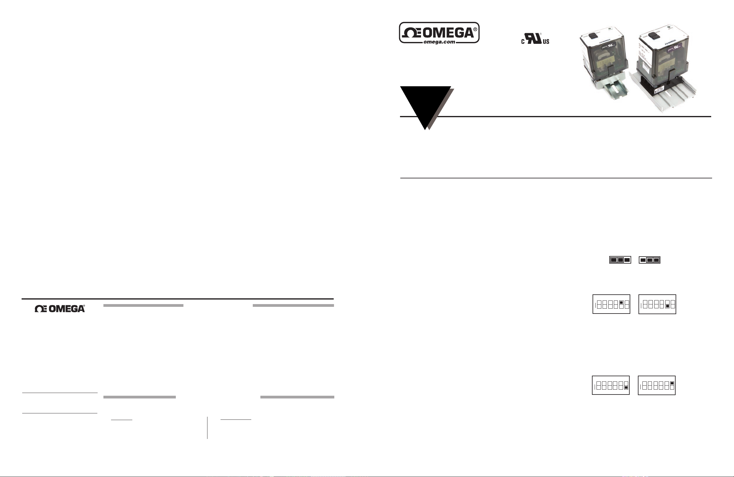
SMSC-1
DC Input, Field Configurable
Signal Conditioner
INSTRUCTION
SHEET
Shop online at omega.comSM e-mail: [email protected]
For latest product manuals: www.omegamanual.info
EliminatesGroundLoops
50%AdjustableFieldCongurableInputRanges:
10mVto100V(200Von-2001),1mAto100mA
FourFieldCongurableOutputRanges:0-5V,
0-10V,0-1mA,4-20mA
Description
The eld congurable SMSC-1 isolator offers wide ranging
inputandoutputcapabilityforscalingandtransmittinganalog
DCsignals.TheSMSC-1willacceptinputvoltagespansfrom
10mVupto100volts,aswellasinputcurrentspansfrom1mA
to100mA.Theinputzeroandspanpotentiometersenable50%
inputzeroandspanadjustability.Forexample,the0-10Vinput
rangecanbeelevatedto5-10V,compressedto0-5Vorsetto
2.5-7.5V.TheAP4380offersfour(4)popularoutputranges:
0-5V,0-10V,0-1mAand4-20mA.The4-20mAcomplianceisa
powerful20VDC.ModelSMSC-1canbeconguredtoaccept
bipolar input ranges and offers selectable normal or reverse
actingoperation.
The SMSC-1 is a 3-port industrial isolator -- the output is
opticallyisolatedfromitsinputupto1500 VDC. The ASIC*basedI/Ochannelisindependently transformer isolated from
theselectable120/240VACpowersupply.
Application
TheSMSC-1eldcongurableisolatorisusefulineliminating
groundloops,convertingsignallevelsandprovidingsignaldrive
andredundancy.ThewiderangingcapabilityoftheSMSC-1
providesquickuniversalsparepartcoverage.
Diagnostic LED
The SMSC-1 is equipped with a dual function LED signal
monitor. The green, top-mounted LED indicates line power
andinput signal status. Activeline power isindicatedby an
illuminatedLED.Iftheinputsignalis10%morethanfullscale
range,theLEDwillashat8Hz.Below0%,theashrateis4Hz.
Options
U
Urethanecoatingofinternalcircuitryforprotectionfrom
corrosiveatmospheres.
Conguration
ThefactorypresetstheSMSC-1inputandoutputto4-20mA,as
showninFigure1.Thesupplypowerisconguredfor120VAC
operation.ForotherI/Oranges,removethefourbasescrews
andcasetoaccesstheI/Ocard.
M5481/0715
ProvidesIsolatedDCOutput
inProportiontoaDCInput
Plug-inInstallation
Selectable120/240VACPower
(9to30VDCAvailable)
ASICTechnologyforEnhancedReliability
RefertoFigure1forcongurationandprogramtheI/Ochannel
asdesired.Replacethecoverbeforeapplyingpower.
Warning:Donot attempt to changeanyswitch settings with
powerapplied.Severedamagewillresult!
Input
1.Positioninputjumper“W1”forCurrent(I)orVoltage(V)input.
V
I
W1
W1
Current
2.Setposition5oftheInputRangeSelectorforUnipolar(e.g.
0to5V)orBipolar(e.g.-5to5V)operation.
ON
>
2 345
1
6
Unipolar
Note:Abipolarrangeselectionwilldoubleanyinputrangefrom
Table1(e.g,10Vspanbecomesa-10to10Vbipolarspan)
3. Set position 6 of the Input Range Selector for Normal or
Reverse operation. Reverse acting produces a decreasing
outputwithanincreasinginput.
ON
>
2 3
1
4
5
6
Normal
4. Using Table 1, congure positions 1 through 4 of the Input
RangeSelectorforthedesiredmaximuminput.Roundthedesired
maximum input value to the next highest range (e.g., 0-70V =
100Vrange).
I
Voltage
ON
>
2 3
1
Bipolar
ON
>
2 3
1
Reverse
V
465
4
5
6
Page 2
Output
Warning:
Donotconguretheoutputrangeswith the power
on.Damagetounitmayresult.
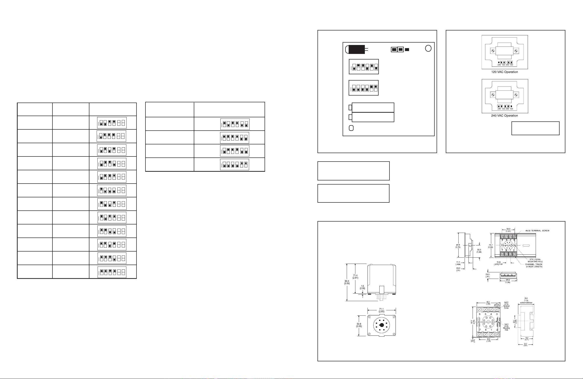
1.UsingTable2,congureOutputSelectorforoneofthefour
(4)standardoutputs.
Power
1.ConguretheACjumpersforeither120or240VACoperation.SeeFigure2.
Table 1: SMSC-1 Input Ranges
Calibration
1.ConnecttheinputtoacalibratedDCvoltageorcurrentsource
andapplypower.Wait1hourforthermalstabilitybeforemonitoringthevoltage/currentoutput.RefertoPINCONNECTIONS.
2.Setthecalibratortothedesiredminimuminputandadjust
theZero,20-turn,potentiometerfordesiredminimumoutput.
3.Setthecalibratortothedesiredmaximuminputandadjust
theSpan,20-turn,potentiometerfordesiredmaximumoutput.
4.Repeatsteps2and3forbestaccuracy.
Table 2: SMSC-1 Output Ranges
I/O Card Conguration
Diagnostic
LED
ON
Input Range
Selector (SW1)
Output Range
Selector (SW2)
>
1
ON
>
1
2 3
2 3
Top View Diagram
W1
I/V Input Selection
V
I
4
6
5
4
6
5
Voltage* Current*
20mV 2mA
50mV 5mA
100mV 10mA
200mV 20mA
500mV 50mA
1V 100mA
2V
5V
10V
25V
50V
100V
Input Range Selector
(SW1)
ON
4
2 3
1
ON
1
ON
>
1
ON
>
1
ON
>
1
ON
>
1
ON
>
1
ON
>
1
ON
>
1
ON
>
1
ON
>
1
ON
>
1
2 3
2 3
2 3
2 3
2 3
2 3
2 3
2 3
2 3
2 3
2 3
5 6
4
5
4
5
6
4
5 6
6
5
4
4
6
5
4
5
6
4
5
6
4
5
6
4
5 6
4
5 6
4
5 6
* Use jumper (W1) to congure voltage or current input. All unipolar
ranges are zero based.
Range*
0 to 10V
0 to 5V
0to1mA
4to20mA
Output Range Selector
(SW2)
ON
>
ON
>
ON
>
ON
>
4
2 3
1
2 3
1
2 3
1
2 3
1
6
5
4
5 6
4
5 6
6
4
5
Span
Zero
Top
Figure1:SMSC-1I/Ocardfactorycalibration:
4-20mAinputandoutput(shownsidewaystoviewswitches)
Warning:DonotcongureI/Oswitch
rangeswithpoweron.Damagewill
result!
Warning:Applyingvoltagetothe
inputwithW1incurrent(I)position
willresultindamagetotheunit.
Mounting
Allmodulesfeatureplug-ininstallation.ModelSMSC-1usesan8-pin
base,eithermoldedsocketSKT-SM-8PorDINsocketSKT-DR-8P.
Dimensions
Dimensionsareinmillimeters(inches)
Warning:Donotchange
withpowerconnected!
Figure2:120/240VACSelection
SKT-SM-8P (Track/Surface)
Mark II
SKT-DR-8P (DIN Rail)
 Loading...