

Page 1
1 | P a g e R e v . 1 . 7 M a n u a l P a r t N o : 06- 1 8 3
I s s u e 13/ 03/ 2 0 2 4
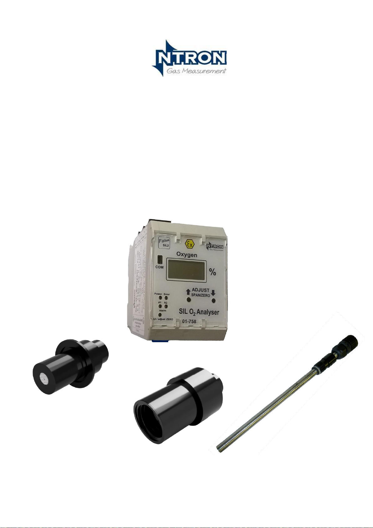
The
SIL O
2
Analyser
User Operation Manual
Rev. 1.7
Manual part No: 06-183
13/03/2024
Page 2

2 | P a g e R e v . 1 . 7 M a n u a l P a r t N o : 06- 1 8 3
I s s u e 13/ 03/ 2 0 2 4
Page 3

3 | P a g e R e v . 1 . 7 M a n u a l P a r t N o : 06- 1 8 3
I s s u e 13/ 03/ 2 0 2 4
Contents
1. Introduction .................................................................................................................................................... 7
1.1 The purpose of this User and Operation Manual................................................................................... 7
2. Installation and Operation ............................................................................................................................... 8
2.1 Notes for a safe installation ................................................................................................................... 8
2.2 Installation ........................................................................................................................................... 10
2.2.1 Mounting the SIL O2 Analyser....................................................................................................... 10
2.3 Electrical and Interface Connections ................................................................................................... 11
2.3.1 Sensor Input and Customer Interface Wiring.................................................................................. 11
2.3.2 Operational Settings and Wiring Configuration ............................................................................. 12
2.3.3 Typical Relay and Analogue Output Configuration ....................................................................... 13
2.3.4 Sensor Process Interface ................................................................................................................. 15
2.3.5 Sensor Process Connection options ................................................................................................ 16
2.3.6 Sensor Electrical Connection .......................................................................................................... 17
2.3.7 EMC Considerations ....................................................................................................................... 17
2.4 Operation ............................................................................................................................................. 18
2.4.1 In Service Operation ................................................................................................ ....................... 18
2.4.2 Calibration Requirements Overview ............................................................................................... 18
2.4.3 Calibration Procedures .................................................................................................................... 19
2.4.4 Setting the Zero point. .................................................................................................................... 21
2.4.5 SPAN Calibration ........................................................................................................................... 22
.......................................................................................................................................................................... 22
2.4.6 Alarm levels and Configuration Changes. ...................................................................................... 22
2.5 Testing ................................................................................................................................................. 23
2.5.1 Partial Proof Testing ....................................................................................................................... 23
2.5.2 Full Proof Testing ........................................................................................................................... 23
2.5.3 Alarm Level Testing ................................................................................................ ....................... 23
2.5.4 Trip Function Testing ..................................................................................................................... 24
3. Operational safety and maintenance instructions.......................................................................................... 24
3.1 Fault conditions-defined special state. ................................................................................................ 24
3.2 Analyser Internal Diagnostic fault ...................................................................................................... 25
3.3 Troubleshooting .................................................................................................................................. 25
Possible Faults and their solutions ................................................................................................ ........................ 25
3.3.1 Possible Sensor Faults .................................................................................................................... 26
4. Specifications................................................................................................................................................ 28
5. Appendices ................................................................................................................................................... 34
Page 4

4 | P a g e R e v . 1 . 7 M a n u a l P a r t N o : 06- 1 8 3
I s s u e 13/ 03/ 2 0 2 4
Revision History
Revision No.
Change Description
Date
0
First Issue
19-10-2018
1
Note added for non-ATEX Sensor usage
22-10-2018
1.1
Reference to 15% O2 in trouble shooting section removed.
30-11-2018
Calibration Span instruction amended and note added.
1.2
Safe use references added to various parts of manual.
11-11-2019
1.3
Proof Testing details expanded
18-12-2019
1.4
CE Certificate amended for SIL O2 in the appendix.
24-07-2020
1.5
Pressure range for sensors added (Page 15, 25)
02/07/2021
1.6
Changes and additions due to SIL Assessment review.
29/11/2023
1.7
Changes and additions due to EN50104 & IECEx Certification.
13/03/2024
Page 5

5 | P a g e R e v . 1 . 7 M a n u a l P a r t N o : 06- 1 8 3
I s s u e 13/ 03/ 2 0 2 4
IMPORTANT NOTES FOR THE SAFE USE OF THIS PRODUCT
a. This Ntron SIL O2 Analyser and Sensor is a SIL 2 capable product. In itself, this
product does not make any end user application into which it is incorporated, a SIL 2
compliant system.
b. It is the responsibility of the end user to perform the integration of the Ntron SIL 2
product and to assess and determine the operational phases and safety lifecycle of the
complete SIL Safety Integrated System (SIS) into which the Ntron SIL2 product is to
be incorporated.
c. To achieve this, the end user must have the appropriate competency or engage the
services of a competent external consultancy service.
d. To safely integrate the Ntron SIL2 product, the Ntron SIlO2 Safety Manual
Documents will need to be consulted depending on the model of Ntron product that
has been supplied.
The complete suite of relevant manuals is listed below:
• Ntron SILO2 and OC-25 and OC-26 Safety Manual
• Ntron SIL O2 and Oxyprobe Safety Manual
• SILO2 Software Manual (for remote software operation when applicable)
• Ntron Sample Conditioning Safety Assessment Report when applicable
• This user manual. (Applicable to all models)
Additional Safety notes:
(i) To ensure continued safe operation of this product, the following system critical
parameters should be observed.
(ii) Sensor Shelf Life: See specification section of this manual.
(iii) Sensor Operational life: See specification section of this manual.
(iv) The above Sensors use Solid State Electrochemical Technology. As such, the
output signal falls over the lifetime of the Sensor, culminating in potentially Zero
output at end of life. The SIL O2 Analyser will not automatically detect a failed
Sensor (e.g. zero output signal due to failed Sensor will not be automatically
announced) The detection of failed sensor must be facilitated by the control
protocols of the Safety Instrumented System (SIS) designer/integrator (See item c
above and Calibration section 2.4.1 to 2.4.4 of this manual)
Page 6

6 | P a g e R e v . 1 . 7 M a n u a l P a r t N o : 06- 1 8 3
I s s u e 13/ 03/ 2 0 2 4
Page 7
7 | P a g e R e v . 1 . 7 M a n u a l P a r t N o : 06- 1 8 3
I s s u e 13/ 03/ 2 0 2 4
1. Introduction
The Ntron SIL O2 Analyser is a ATEX approved SIL 2 rated Oxygen measuring instrument. It contains three
programmable alarm settings, industry standard Analogue Output(active source) and a non-programmable safety
trip relay. The range of operation is 0 to 25% Oxygen. The Reasolution is to 0.01%.
The Oxygen Sensor is IECEx and ATEX certified for hazardous area operation and is prohibited for use
in hazardous areas of enriched Oxygen concentration, that is, above 21% by volume. Use in such
enriched atmosphers would be beyond the certified range of the equipment and could result in
hazardous conditions for personnel and equipment.
Together with one of the range of Ntron ATEX approved Oxygen Sensors, it forms a SIL2 capable
measurement unit which can operate on its own or as part of a larger installation for Inertisation applications.
Note. Non-Atex (Ex) Sensors variants of the models listed in the manual may also be used with the SIL O2
Analyser as long as they are installed in a Non-ATEX (Ex) or ‚Safe‘ area or zone. The Sensors can be
located in line into a user’s process or located within an Ntrom Sample Conditioning panel.
The Alarm settings are typically factory set according to the end user’s requirements and are not adjustable by
the user. Interface software and hardware is available for the user to perform such adjustment functions
themselves. Contact Ntron for further details.
1.1 The purpose of this User and Operation Manual
This Manual is limited to providing the user with necessary details on installation, interface wiring, operation
and maintenance of the SIL O2 Analyser and Oxygen Sensor, to ensure safe and reliable operation of this
Analyser and Sensor unit.
Note: This manual does not cover the design or application of a safety Instrumented System (SIS) into
which the SIL O2 Analyser unit may be incorporated. This activity is described in the revevant issue of
Safety Manual document and available on request from Ntron. A table of calculated failure frequencies
for this SILO2 Analyser and Sensor combination is included in the Specifications section 4 of this manual.
This manual also does not detail the implementation of this equipment into a sample gas delivery system.
Basic guidlines are given in various places throught this manual but the delivery system User Manual and
Safety Manual must be consulted for the complete information required.
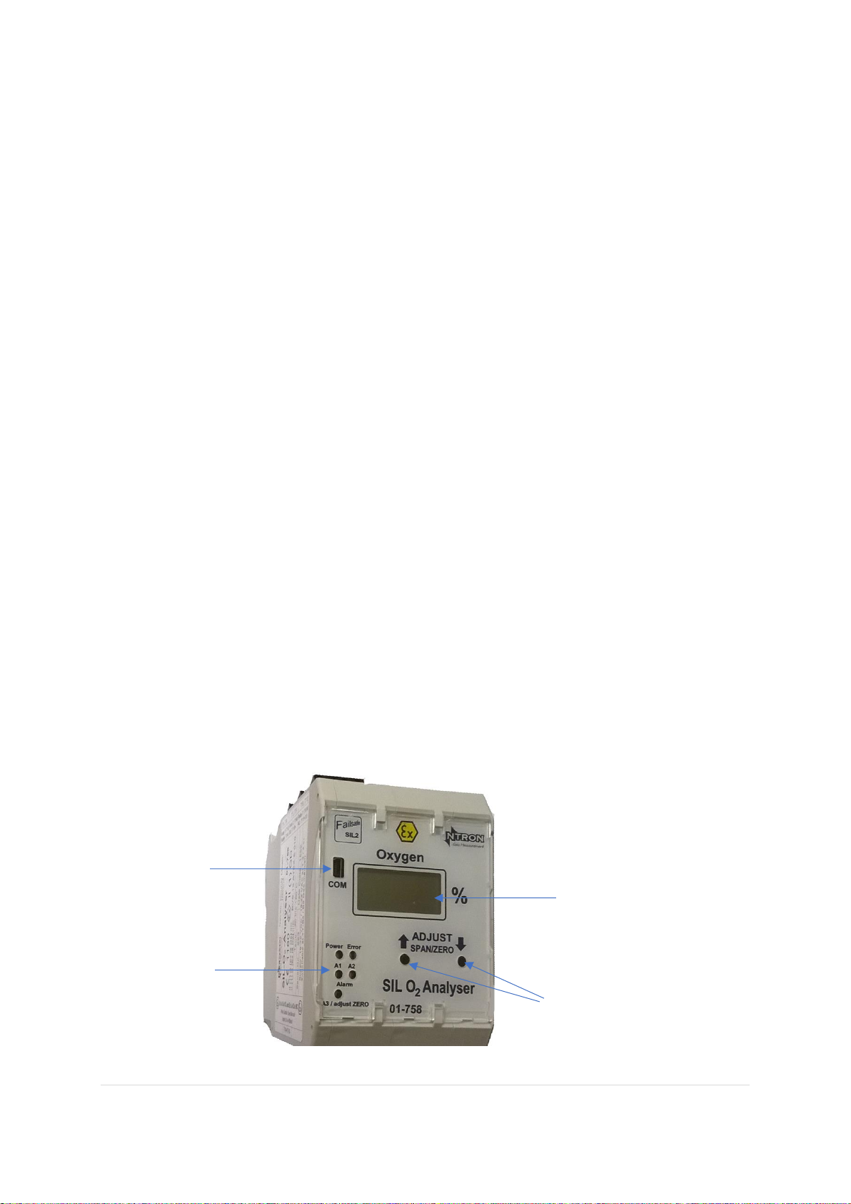
Increase (UP) and
Decrease (Down)
Pushbuttons. Pressing
simultaneously enables
entry into the
calibration mode.
Power, Error/Fault and
Alarm Level indicators
RS232
Communications
connection
The main user interface features
4-Digit LCD
Display/Readout
Page 8
8 | P a g e R e v . 1 . 7 M a n u a l P a r t N o : 06- 1 8 3
I s s u e 13/ 03/ 2 0 2 4
Installation and Operation
1.2 Notes for a safe installation
Please do not short-circuit the + and -ve sensor cables while connecting to the SIL O2 Analyzer. This
could damage the sensor.
The SILO2 Analyser must be mounted within a lockable cabinet or enclosure, with access secured by a
high torque lock mechanism.(Typically a lock requiring the use of a key or tool)
This system can also be used in a non-Ex area application. In all applications, the SIL O2 Analyzer Din
rail module is always located in the non-Ex area!
Assignment of the mounting rail housing terminals with intrinsically safe circuits and non-intrinsically
safe circuits is indicated on the nameplate and is clearly indicated. In addition, the 4-pin terminals of
intrinsically safe circuits follow the standard color protocol for intrinsically safe terminal connections and
are coloured Blue. Connections for intrinsically safe external circuits are arranged in such a way that, in
accordance with EN 60079-11, the exposed parts are at least 50 mm from the exposed connections and
parts of the non-intrinsically safe circuits.
For safe operation, a protective ground/earth connection to terminal 13 or 15 should be made.
Assembly / disassembly, installation, operation and maintenance may only be performed by qualified
personnel in accordance with regulatory requirements and the SIL O2 Analyser Manual.
During installation, the technical data and the electrical values of the connected circuits must be
respected.
Electrical supply. The SILO2 Analyser operates with a Safety Extra low Voltage (SELV) supply. (See
specification section in this manual)No special precautions are necessary but the SELV supply to the SIL
O2, if generated from a Mains power source, that mains power source and associated wiring must be in
accordance with IEC/EN standards and is the responsibilty of the user to provide and to ensure correct
and safe installation of such.
When the SIL O2 analyzer is integrated into another system, also refer to the system manual for
additional operational information.
The Ntron SILO2 Analyser is designed for use with a range of Ntron ATEX certified Oxygen Sensors to
form a measurement system.These Sensor options are detailed in the Specification section of this manual.
If the SIL O2 Analyser has been supplied with a Sensor, the two units will have been calibrated at the
Ntron factory prior to delivery. Otherwise, if a Sensor is supplied separately from the SIL O2 Analyser, a
calibration will be required prior to putting the system into operational service.
The Ntron Sensors suitable for use with the SIL O2 Analyser are listed in the Installation section which
follows.
Page 9
9 | P a g e R e v . 1 . 7 M a n u a l P a r t N o : 06- 1 8 3
I s s u e 13/ 03/ 2 0 2 4
The SIL O2 oxygen analyzer is an associated explosion-proof [Ex ia] IIC or [Ex ib] IIC electrical device
and should always be used outside potentially explosive areas (in a safe area). Only electrical circuits,
certified as intrinsically safe, can be connected to other intrinsically safe circuits in the Ex zone.
Before operation, the intrinsic safety must be verified for the SIL O2 analyzer circuit connected to the
circuit of other equipment, including the interconnecting cabling.
The data contained in the EC test certificate and the regulations of EN 60079-14: 2011-10 must be
observed.
The Sensors are ATEX rated devices and have certain conditions of use assigned. The models OC-25 and
OC-26 are available in Acetal or Stainless Steel body materials denoted by a suffix letter, M.
Note. Non-Atex (Ex) Sensors variants of the models listed in the manual may also be used with the
SIL O2 Analyser as long as they are installed in a Non-ATEX (Ex) or Safe area or zone.
For Plastic (Acetal-bodied) Sensors, the following instructions apply;
The Sensor should be installed in such a way that it is not subject to impact by other objects and should
not be located close to additional heat sources. Note the ambient temperature range as it appears on the
Sensor labelling.
Care must be taken when installing equipment with plastic enclosures or plastic parts of enclosures to
ensure that the equipment is protected from any situations that could cause a build up of static charge. The
equipment must not be installed into locations in which it could come into contact with, through normal
or abnormal circumstances, fast moving dust laden air/gas or non-conductive fluids. The equipment must
be cleaned only with a damp cloth.
For Stainless Steel body Sensors, (’M‘ suffix to model type) the following instructions apply;
When installing equipment with Metal enclosures, earthing of the metal enclosure must be ensured
to avoid the potential of electrostatic discharge.
Further installation instructions for applicable to both the SILO2 Analyser and Oxygen sensor can be
found in EN Standard 60079-14 and EN 60079-29-2.
Prohibited gases. Some gases can cause irrepererable damage to the Oxygen sensor, shortening its life
span. Typically, these are any acidic gases which occur with a relative humidity (RH) of 60% or greater.
Pre-conditioning equipment is available to mitigate against such conditions ans should be taken into
account at the planning stage of a customer installation.
(Acidic gas e.g. Hydrogen Sulphide)
Gas Cross references:
A corresonding deviation in sensor output will occur in the presense of the following gases as a
percentage of full gas volume.:
Carbon Monoxide 10%
Carbon Dioxide 30% ok with >60% but cross sensitivity will increase.
Hydrogen 30%
Saturated Hydrocarbons % range
<0.05% Vol O2 signal change for the above concentrations.
Background Gases such as Helium and Ozone will influence the measurement of Oxygen and distort the
measured value of Oxygen to an extent dependant on the concentration of such gases. Test measuremts
would need to be taken to establish the extent of influence and any subsequent alarm configuration.
Page 10
10 | P a g e R e v . 1 . 7 M a n u a l P a r t N o : 06- 1 8 3
I s s u e 13/ 03/ 2 0 2 4
1.3 Installation
Planning:
The installation must be in accordance with the local electrical codes and taking into account the details
in the Specification section of this manual.
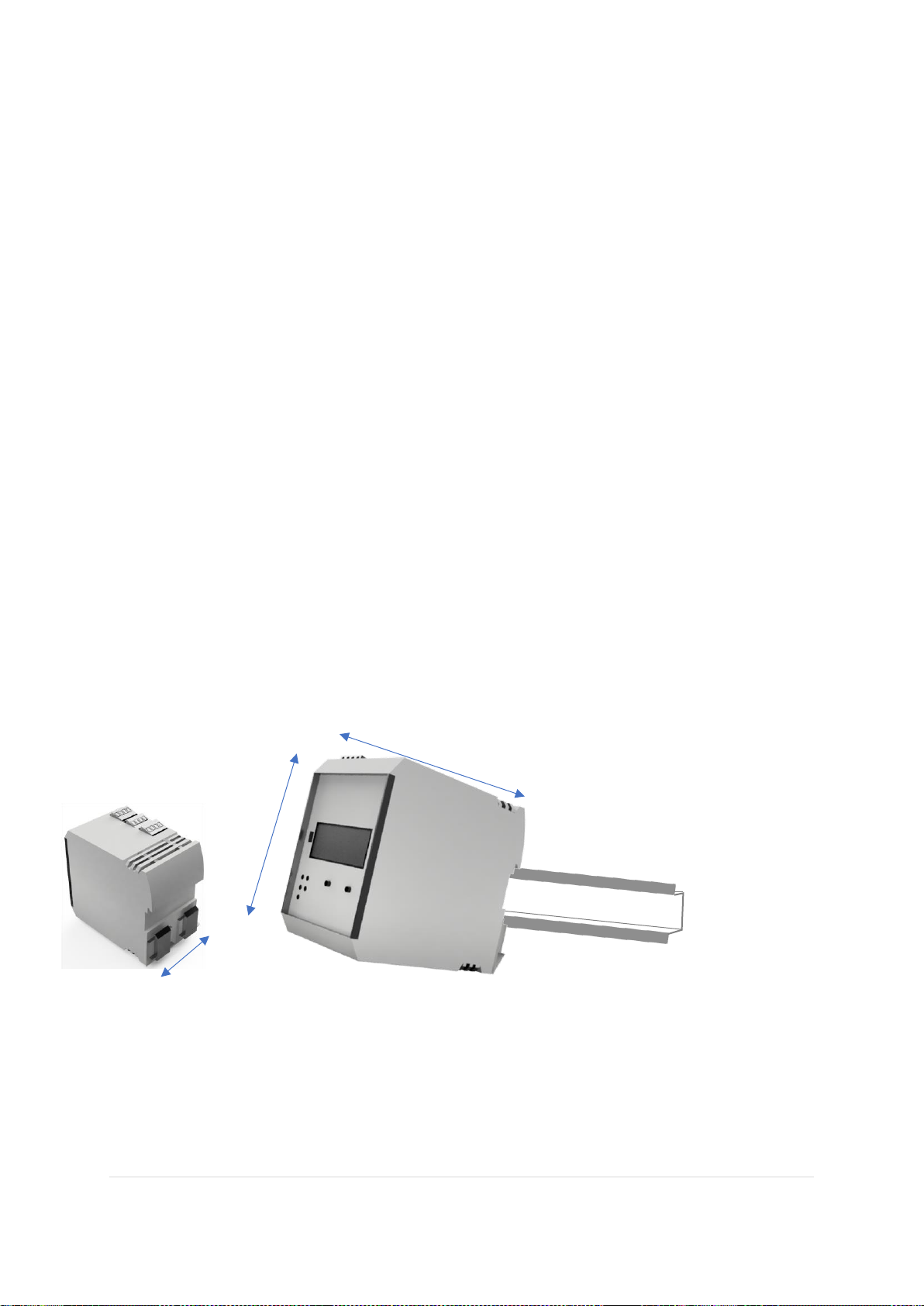
The SIL O2 analyzer is designed for DIN rail mounting and can be supplied mounted in an additional
enclosure or provided without an additional enclosure for customer mounting in a system enclosure or
control panel.
The Sensor option chosen will determine the process connection/installation for that Sensor type. The
Sensor types and related process connections are given below.
Sensor Type: Process Connection:
Model OC-25 and OC-25M Ntron Sensor base, Flow Through or Tri-Clamp
Model OC-26 and OC-26M KF40 Flange
Model OC-200’Oxyprobe‘ series Bushing insert or Extract* Probe Holder
The Sensor is typically supplied with a correcponding connection cable of either standard length or to a
customer specified length. Cable length and routing should be determined at the planning stage.
*The Ntron OxyExtract Manual or Automatic probe insertion mechanism.
1.3.1 Mounting the SIL O2 Analyser
Mount the SIL O2 Analyser onto 35mm DIN rail as shown. Any Trunking/wireways above and below
the Analyser when in situ, must be positioned so that there is a minimum of 30mm clearance between
such trunking and the Analyser connection terminals. Mounting in other orientations will not affect the
units operation but the display readout will be difficult to read at any position other thant that which is
shown above.
115mm
100mm
67mm
Page 11
11 | P a g e R e v . 1 . 7 M a n u a l P a r t N o : 06- 1 8 3
I s s u e 13/ 03/ 2 0 2 4
1.4 Electrical and Interface Connections
1.4.1 Sensor Input and Customer Interface Wiring
Suitably insulated wire/cable should be used for all interfacing connections with the SILO2 Analyser. Ensure
the wire/cable size is suitable for the maxiumum capacity of the connection terminals (2.5mm CSA) and is of
sufficient rating to convey the intended electrical current, both operational and under fault condtions. The
Sensor cable is supplied by Ntron.
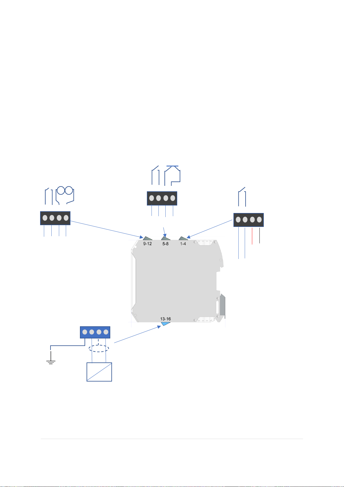
The Ntron ATEX Sensor selected for use with the SIL O2 Analyser as listed in the Installation section
previously, has intrinisically safe parameter values which match the Isolation Barrier output which is built into
the SIL O2 Analyser. The Sensor connects to the Blue terminals as shown below.
The dark Grey terminals are for safe (Non-Ex area) customer interface connections. See the configuration
section on the following page.
Current limitaion in the form of fusing or other suitable method, is required for the user’s external
circuitry connected to the relay contacts shown above, to prevent damage to the relay contacts. The
recommended maximum fuse rating is 0.6 Amps.
The ratings of all the relay contacts are given in the specification tables on page 25 of this manual.
13 14 15 16
+ve -ve
Customer Clean
Earth
O2 Sensor
1 2 3 4
+ - 24 VDC
Relay 1
To customer Circuit
5 6 7 8
Relay 2 Transistor(DO)
To customer Circuit
9 10 11 12
Relay 3 4-20mA (AO)
To customer Circuits
Page 12
12 | P a g e R e v . 1 . 7 M a n u a l P a r t N o : 06- 1 8 3
I s s u e 13/ 03/ 2 0 2 4
1.4.2 Operational Settings and Wiring Configuration
The SIL O2 Analyser has two presettable non-latching# alarm levels and associated Relays, referred to as RL1
and RL2. It also has a third presettable alarm level with an associate Transistor Digital Output (DO) The
programmed setting of these outputs can vary depending on application. These alarm levels are factory set to
the user’s requirements and cannot be changed manually at the SILO2 Analyser. Interface and programming
software running on a PC is required to access and change these alarm settings and associated functionality.
This remote sofware complete with interfacing cable is available from Ntron. And its use and operation is
detailed in the Ntron SILO2 Software Manual. Access to this remote software should be password protected by
the user.
The Inspection and Calibration certificate supplied with each SIL O2 Analyser and Sensor unit will detail the
factory set alarm values and configuration.
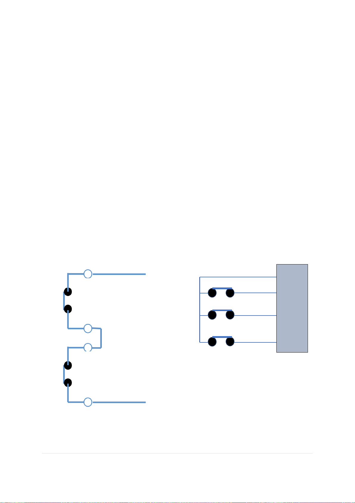
The SIL O2 Analyser has a main non latching# trip Relay referred to as RL3. This is not programmable and is
normally open(contacts)/de-energised when the Analyser is not under power. The Relay energises and its
associate contacts close when power is applied and the Analyser and Sensor are healthy and ready to operate.
The Analogue output is an industry standard 4-20mA active source output. The connected circuit should be of
maximum resistance 420 ohm.
To meet the SIL 2 operational requirements as an Analyser and Sensor unit, the main trip Relay is required to be
connected in series with other elements within the Analyser as shown in the diagram below.
Alternatively, the alarm level Relays and the Main Trip Relay can be connected individually into a suitable
safety PLC with an appropriate SIL safety assessment undertaken. In all case of implementation of the SIL2
Analyser, a SIL assessment must be undetaken of the complete Safety Instrumented System.
Latc
*Special case for use of the 4-20 mA analogue output within a safety system
# Latching of any of the above Relay output signals will be made, as appropriate within the
user’s control equipment.
Relay 3 Main Trip
Relay 1 or 2
1/5
2/6
9
10
Relay 2
Relay 3
Relay 1
SUITABLE SIL SAFETY PLC
1 2 5
6 9 10
Page 13
13 | P a g e R e v . 1 . 7 M a n u a l P a r t N o : 06- 1 8 3
I s s u e 13/ 03/ 2 0 2 4
Whilst the 4-20 mA Analogue output from the SILO2 Oxygen Analyser is SIL capable, the implementation of
it into a SIL2 capable system presents the end user with certain onerous requirements for SIL compliance and
so no connection examples are given in this manual for SIL rated operation.
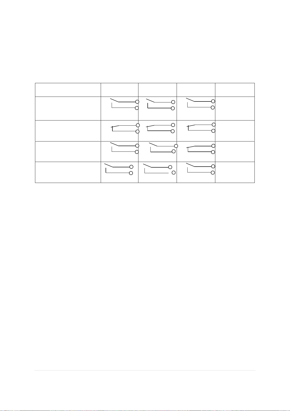
1.4.3 Typical Relay and Analogue Output Configuration
Power to the Analyser
Relay
Contact 1
Relay Contact
2
Relay Contact
3
Comments
Power Off
(All relay contacts in Fail
Open condition)
Relays
De-energised
Power on and system
good/healthy
**
** All Relays
Energised
Power on and O2 alarm
level(s) reached
* *
Relays 1 & 2
De-energised
Power on and System fault
**
** All Relays
De-energised
The relays RL1 and RL2 are programmed to respond to the measured Oxygen level setpoints (Alarms), rising
or falling in the range 0-25% Oxygen. These are pre-set to the customer’s requirements.
They operate in ‘Fail Safe’ mode which means that they are energized (under current), presenting a closed
contact to the customer/user when the SIL O2 module is under power and the status is healthy/good.
When at a level setpoint (Alarm) or when the SIL O2Analyser is not-powered, the relays are de-energised (not
under current), presenting an open contact to the customer/user. This is also known as ‘Fail Open’ (FO)
condition.
Relay RL3 serves as the Internal diagnostic Output Relay and is always fail safe -energised(closed contact)
healthy/de-enegised when an internal fault event occurs or an external fault detected by the internal diagnostics
of the SIL O2 Analyser.
Transisitor (DO)
This is an NPN device that can switch 24VDC and can be configured to be normally open or normally closed.
Analogue 4-20mA
This is an active output and requires connection to a passive external circuit suitable for proper operation.
It is set to the range 0-25% Oxygen / 4-20mA (0% Oxygen = 4mA, 25% Oxygen = 20mA.)
This range can not be adjusted.
If the 4-20 mA output is not used, the SIL O2 terminals T11 and T12 must be wired by the user. This output is
internally connected in series with the SIL O2 Analyzer digital display, which will not work if the
aforementioned terminals are in open circuit! Connecting cables can be single core panel wiring cables or single
pair screened cable depending on installation requirements. Techical specifiactions of the selected cable should
meet the requirements on the following page.
Page 14

14 | P a g e R e v . 1 . 7 M a n u a l P a r t N o : 06- 1 8 3
I s s u e 13/ 03/ 2 0 2 4
Maximum line resistance for the mA output
Analog output circuit (AO) for constant current:
Max. range:
0...22 mA Standard
range: 0/4-20
mA
Load: max. 420
Ohm by 20 mA Accuracy:
0,02 % of final value
Load influence: <0,005 %
The maximum load for the analog output circuit is the sum of the cable resistances
and the input resistor (shunt) the following assembly:
R
Load
= 2x RC + R
Shunt
≤ 420 Ω
Cable resistance:
R
C
= l x ϱ x A
-1
[Ω] ϱ = 0,01785
[Ω mm2 m-1]
A =
0,25 x d2 x π [mm2]
Calculation of cable length (distance):
l = 0,5 (420 Ω - R
Shunt
) x ϱ
-1
x A [m]
Cable (C) lengths as a function of cable diameter and input resistance:
R Shunt = 100
C Dia mm C Cross section mm
2
C Length m C Length km
0.6 0.283 2543 2.54
0.7 0.385 3460 3.46
0.8 0.502 4512 4.51
0.9 0.636 5716 5.72
1.0 0.785 7056 7.06
R Shunt = 200
C Dia mm C Cross section mm
2
C Length m C Length km
0.6 0.283 1748 1.75
0.7 0.385 2379 2.38
0.8 0.502 3102 3.10
0.9 0.636 3930 3.93
1.0 0.785 4851 4.85
Page 15
15 | P a g e R e v . 1 . 7 M a n u a l P a r t N o : 06- 1 8 3
I s s u e 13/ 03/ 2 0 2 4
R Shunt = 300
C Dia mm C Cross section mm
2
C Length m C Length km
0.6 0.283 954 0.95
0.7 0.385 1298 1.30
0.8 0.502 1692 1.69
0.9 0.636 2144 2.14
1.0 0.785 2646 2.65
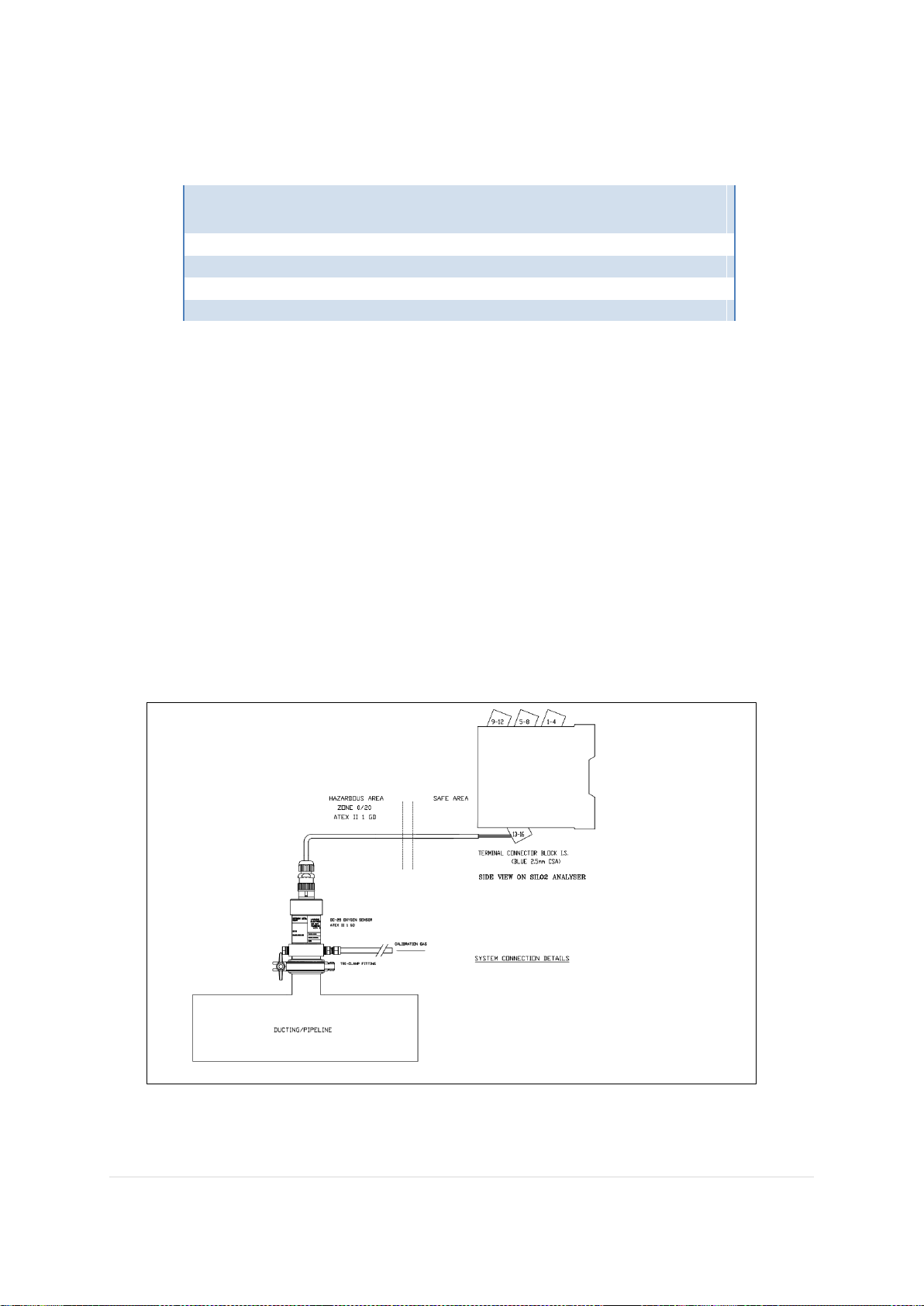
1.4.4 Sensor Process Interface
Gas in which the Oxygen content is desired to be measured can be supplied to the Sensor by means of suitable
pipework and process connections. (See section 2.2). These are accessories to the SILO2 Analyser and Sensor
but in most cases, the OC-25 and OC-25M models will require the use of one type to facilitate operation. (see
next page)
The user should determine the most suitable connection method for their process. The connection accessory is
not included in any product performance certifification and does not modify the performance or specification of
the equipment if correctly selected and installed. A typical In-Line measurement application with Tri-Clamp
accessory is illustrated below. The Sensors should be oriented vertically or at no more than 90 degrees to the
vertical plane. The gas delieverd to the Sensor should be of a constant flow rate and pressure to ensure a
consistant level of response to changes in Oxygen concentraion level within the sampled gas stream. See the
specifications section of this manual
Page 16
16 | P a g e R e v . 1 . 7 M a n u a l P a r t N o : 06- 1 8 3
I s s u e 13/ 03/ 2 0 2 4
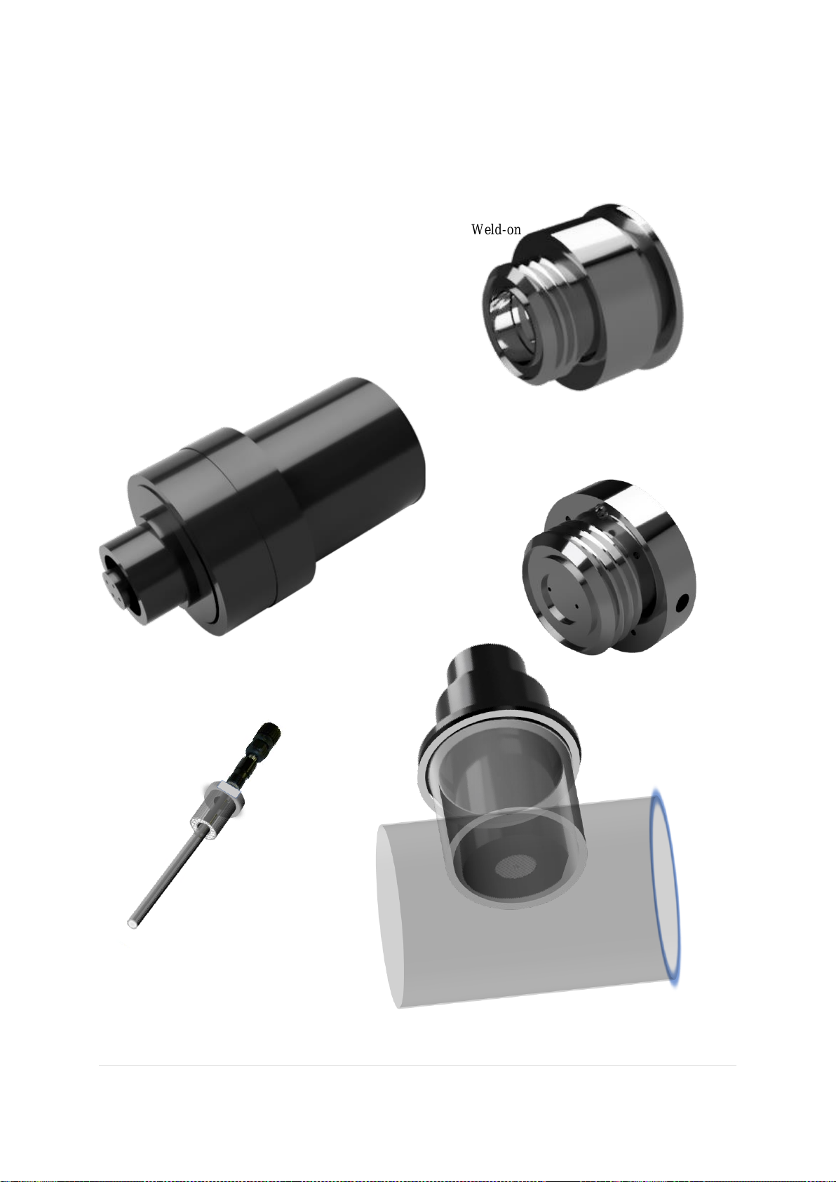
1.4.5 Sensor Process Connection options
The Sensors are suitable for mounting directly onto process
Lines via a selection of process fittings or can be located within sample delivery
System equipment. The electrical signal connectors
are rated to IP67.Acetal bodied sensors shown.
Other process connetion options include ANSI Flange and Weld-on
Base.
Flow Through Sensor Base
OC-25 Sensor
OC-26 Sensor KF40 Process fitting
KF40 Fitting into process Pipeline.
OC-200 Sensor with Screwed Bush Process
fitting
Tri Clamp Sensor Base
Page 17
17 | P a g e R e v . 1 . 7 M a n u a l P a r t N o : 06- 1 8 3
I s s u e 13/ 03/ 2 0 2 4
1.4.6 Sensor Electrical Connection
The Sensors are Solid State Electrochemical Amperometric Oxygen sensing devices.
The output voltage signal generated by all the sensor models is in the millivolt range.
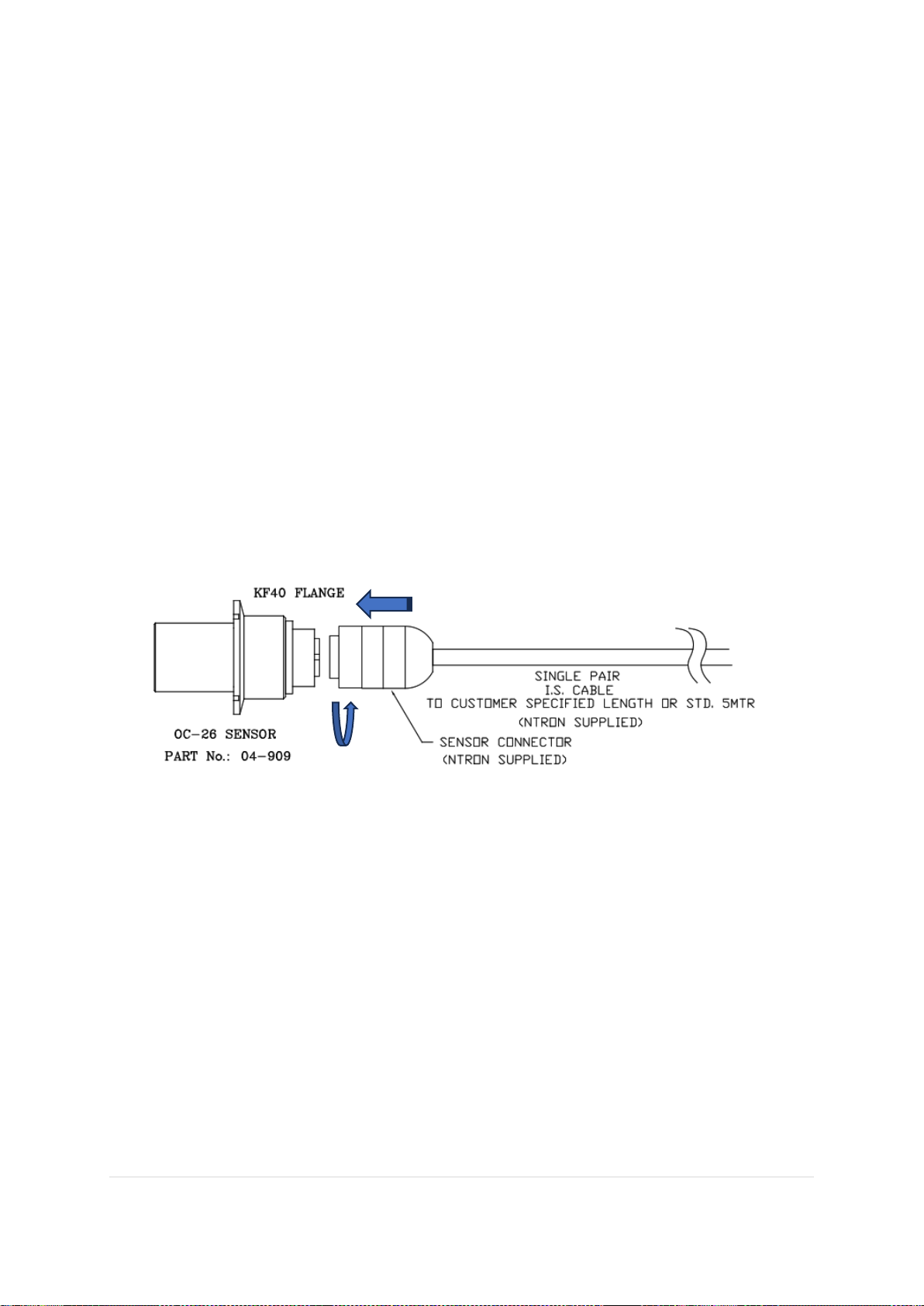
This output voltage signal is conveyed from the sensor to the SILO2 Analyser via a connector and cable
assembly. This is typically pre-made to a given length by Ntron and supplied as part of the SILO2
Analyser and sensor package.
Depending on the sensor model housing material, Stainless Steel or Acetal, a secure electrical connector
is used which requires the user to push on and then screw down to lock. This prevents erroneous or
accidental disconnection of the Sensor.
If a longer cable length outside the standard range is requested of Ntron by the customer or is fitted by
the customer themselves, the specific cable parameters must first be assessed for Ex compatibility and
Operational compatibility before proceeding to install.
Example shows Acetal-bodied OC-26 and cable with connector.
1.4.7 EMC Considerations
The SILO2 Analyser unit is to be located typically in a protective enclosure which meets the required
electrical and EMC standards. The Sensor cable is shielded and EMC compatible. The aspect of
excessive potential EMF interference may pose an issue for long cable runs of the Sensor when routed
via strong EMF sources. In addition, at very low Oxygen measurement levels, the signal from the
Oxygen Sensor to the SilO2 Analyser will be very small and more susceptible to superimposed EMF
currents/voltages. Good planning of a prospective installation should take the foregoing into account.
Relevant EMC standards are given in the specifications section of this manual.
Page 18

18 | P a g e R e v . 1 . 7 M a n u a l P a r t N o : 06- 1 8 3
I s s u e 13/ 03/ 2 0 2 4
1.5 Operation
1.5.1 In Service Operation
Before turning on the SIL O2 analyzer for the first time or after disconnecting the sensor for maintenance /
replacement, make sure that a working sensor is connected. Otherwise, the SIL O2 analyzer will go into failure
mode, with the red error indicator on and the RL3 relay disabled. As the fault circuit performs a cyclic check
every 30 seconds or so. When the sensor is connected, resetting the red indicator and relay 3 occurs
automatically, but it is advisable to power off the system to allow the sensor to be disconnected / reconnected
under normal circumstances, if possible. There is no required sensor warm up time.
Turn on/apply power to the SIL O2 Analyser. There is no warm up time requirement. Stabiliastion of gas flows
is the main time- to- measurement factor from power up.
When operating under normal process/system conditions, the SIL O2 Analyser will continously monitor the
Oxygen concentration transmitted by the Sensor in the process and give a digital readout of the measured
Oxygen in percentage.
This measurement is converted into a 4-20mA Source output signal proportional to the Oxygen being measured
which can be monitored by the user.(See special note on page 12 of this manual).
If an Alarm level event occurs, the relevant programmed output device will operate (Relay or Transistor) and
the interface circuit to the user equipment will be interrupted. When the event causing the alarm condition is
removed or corrected, the output devices will automatically reset to their operational state. For further alarm or
fault events and their conditions, please see the troubleshooting guide in section 3.3 of this Manual.
1.5.2 Calibration Requirements Overview
The SIL O2 Analyser and Sensor unit requires periodic calibration checks otherwise referred to herewith as a
Partial Proof Test, and when necessary and appropriate, re-calibration. The timing between such checks and recalibration being determined by the application and process requirements and the SIL safety related data to be
consulted in the relevant Ntron SILO2 Safety Manual. A Full proof test is required at 1 yearly intervals. The
proof testing and calibration requirements can be itemised as follows and are described in section 2.5 Testing.
• Partial proof test (calibration check)
• Re-calibration
• Full proof test
The maximum allowable Sensor drift within the determined intervals between proof tests is +/-2.5% of the
upper limit of measurement range which is +/-0.625% Vol O2. (See also the Specifications Section of this
manual) If the displayed measurement on the Analyser exceeds these maxium allowble drift values then the
sensor must be considered to have failed and should be replaced.
A calibration check can be performed at any time to confirm measurement accuracy, by applying the required
test gas. Such calibration checks would constitue a partial proof test and may be incorporated into the required
proof testing regime. See section 2.5‚ Testing in this manual. If a calibration check returned an inaccuracy in
measurement but within the maxiumum allowable sensor drift parameters, then a calibration should be
performed.
Page 19

19 | P a g e R e v . 1 . 7 M a n u a l P a r t N o : 06- 1 8 3
I s s u e 13/ 03/ 2 0 2 4
Calibration Gases:
The gas for calibration or calibration check can be supplied via the process line(s) to which the sensor is
connected at the same pressure and flow rate as the sensor encounters during its normal operation.
The overall time to achieve a stable reading can be affected by the length and volume of connecting pipework
conveying the calibration gases to the sensor.
Gases should be applied for a suitable length of time to ensure sufficient and stable volume at the sensor and
stability of the display reading on the SILO2 Analyser. For Zero setting, the Nitron gas should be flowed for a
suffcient time prior to performing the Zero function, to ensure Oxygen/air is purged from the pipework/tubing
feeding the sensor. Stability of the calibrated reading should be observed for a sufficient period of time before
disconnecting the gas supply.
For response time testing as part of a proof testing regime, see the relevant Ntron SILO2 safety Manual.
Span and calibration check: 20.9% O2 Certified gas recommended. Gas tolerance should be within +/-0.4%
V/V of nominal value. This should be the same gas as was used for the last previous calibration to ensure any
sensor drift detected is not as a result of gas tolerance differences. Ambient air can be used if the % volume O2
concentration can be verified by another measuring instrument. The humidity content of the gas should be
within the R/H range of the Sensor. See specification section of this manual. Any changes in test gas used
should be recorded and accounted for in any resulting calibration or calibration check. A periodic calibration is
made according to the intervals given in the relevant SILO2 Safety Manual.
Zero setting: ppb level O2 Nitron gas should be used. A Zero calibration is only required when a new sensor is
fitted. Each Sensor has a small positve Zero offset value which should be calibrated out. A periodic check of the
Zero reading can be made if desired
1.5.3 Calibration Procedures
The SPAN calibration point of 20.9% O2 (Air) is the important setting and typically, if calibration adjustment is
required, this is the value that would be adjusted. This adjustment can be made using ambient air as the
calibration standard or, for greater accuracy, certified cylinder gas at 20.9% O2.
The pressure presented by the calibration gas to the Sensor should be the same as the pressure of the
sample gas normally being measured. All the Sensor types detailed in this Manual for use with the
SILO2 Analyser are Partial Pressure Sensors where the output signal will increase or decrease linearly
with the pressure of gas being measured. There is a recommended range of operational pressure. See
specifications page 25.
It is possible to also adjust the Zero point of the SIL O2 Analyser. Typically this would only be required when
fitting a new/replacement Sensor. A Complete calibration procedure is given on th next page.
Page 20
20 | P a g e R e v . 1 . 7 M a n u a l P a r t N o : 06- 1 8 3
I s s u e 13/ 03/ 2 0 2 4
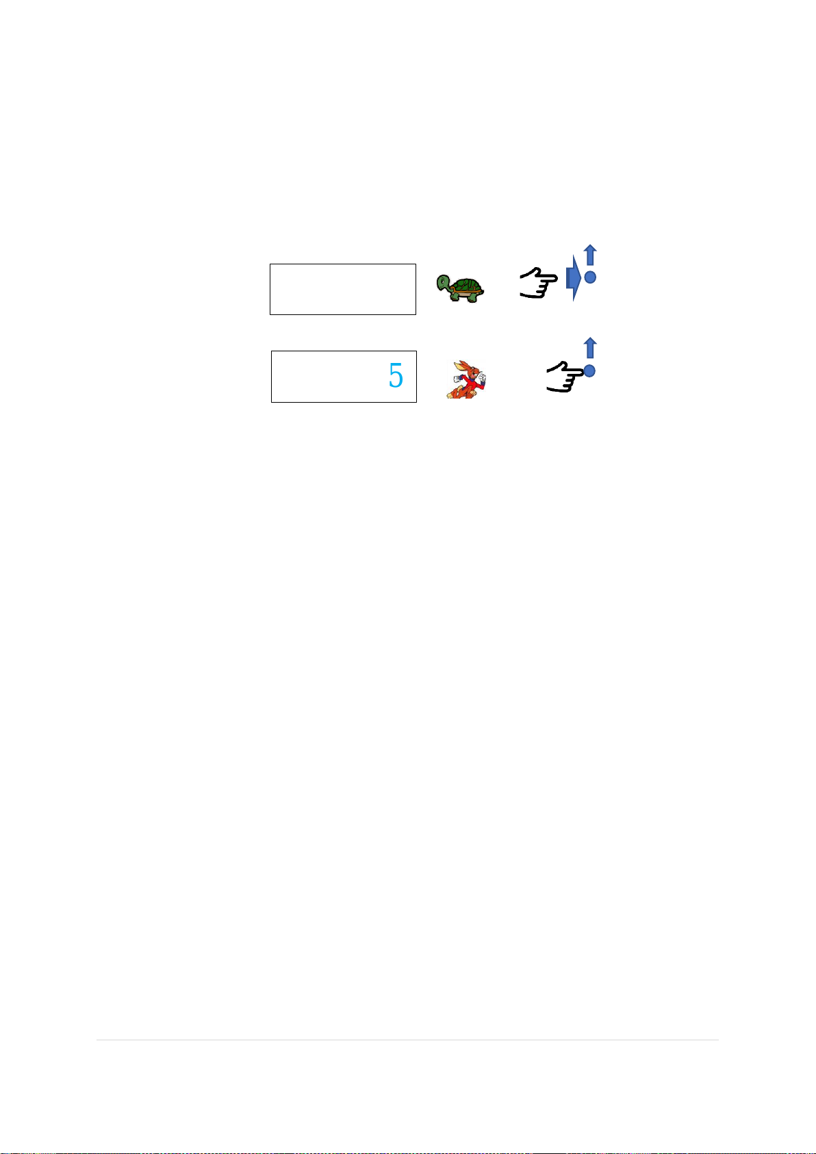
Note: Calibration Adjustment procedure.
The displayed number change starts with the digit to the far right of the decimal point. Press and hold the
Up or Down buttons to change the reading. This gives an accelerated adjustment. More accurate
adjustment is achieved by pressing the Up or Down button at one press (press release, release of press,
etc.). When the display reads 20.9%, the calibration of the range is complete
19.05
19.05
1, 2, 3….
6
6
1-
Page 21
21 | P a g e R e v . 1 . 7 M a n u a l P a r t N o : 06- 1 8 3
I s s u e 13/ 03/ 2 0 2 4
1.5.4 Setting the Zero point.
This must be done each time a new sensor is installed before a span calibration is performed.
Subsequently, a zeroing can be performed periodically as needed but is not required to be part of the periodic
partial proof test.
A zeroing operation requires the application of a zero oxygen gas to the sensor, typically nitrogen of ppb
Oxygen content. Note: Accessing the Zero function when the sensor is in ambient air (20.9% O2) will result in
an error / fault condition.
Depending on the type of sensor installed, zero gas must be applied through a process fitting or calibration
adapter, and be sure to leave a free exhaust at a suitable location so that the sensor does not become pressurized.
The sensors to be used with the SIL O2 unit will generally give a small output at zero oxygen levels. The zero
adjustment function allows the user to adjust this small signal so that the SIL 2 analyzer displays 0.0 when no
oxygen is present in the measured gas.
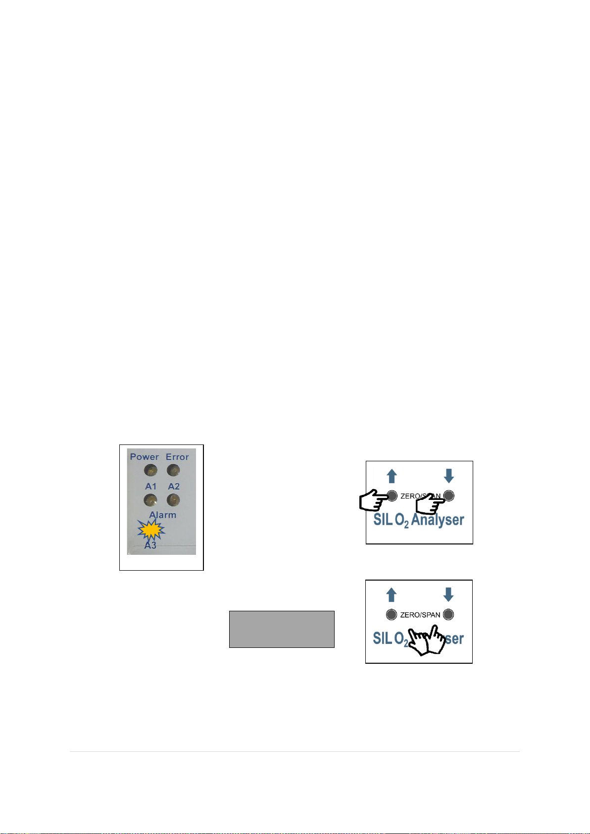
• ZERO mode is activated after pressing the UP and DOWN button simultaneously for more than one
second. As an acknowledgment of receipt, the A3 LED flashes. An adjustment of the indicated value is
made by pressing the UP or DOWN buttons individually as required.
• The change starts with the digit to the right of the decimal point. (00.0) Press and hold the Up or Down
buttons to change the displayed reading. This allows an accelerated adjustment. Accurate adjustment is
achieved by pressing the Up or Down button at one press (press release, release of press, etc.). When
the display reads 0.0% O2, the setting is complete. By simultaneously pressing the two buttons or a
delay of 20 seconds, the ZERO operating mode ends.
`
Note: The Analyser will still monitor the application Oxygen level during all stages of the calibration process
and the alarm levels and associated relays will operate if their setpoints are reached.
0.00
Page 22
22 | P a g e R e v . 1 . 7 M a n u a l P a r t N o : 06- 1 8 3
I s s u e 13/ 03/ 2 0 2 4
1.5.5 SPAN Calibration
This can be done periodically or as needed in accordance with the requirements of the calibration protocol.
Note:
• The SIL 2 analyzer should only be calibrated at 20.9% oxygen.
• If an ambient air calibration is performed, it is recommended to confirm the oxygen level with a
certified portable oxygen analyzer prior to calibration.
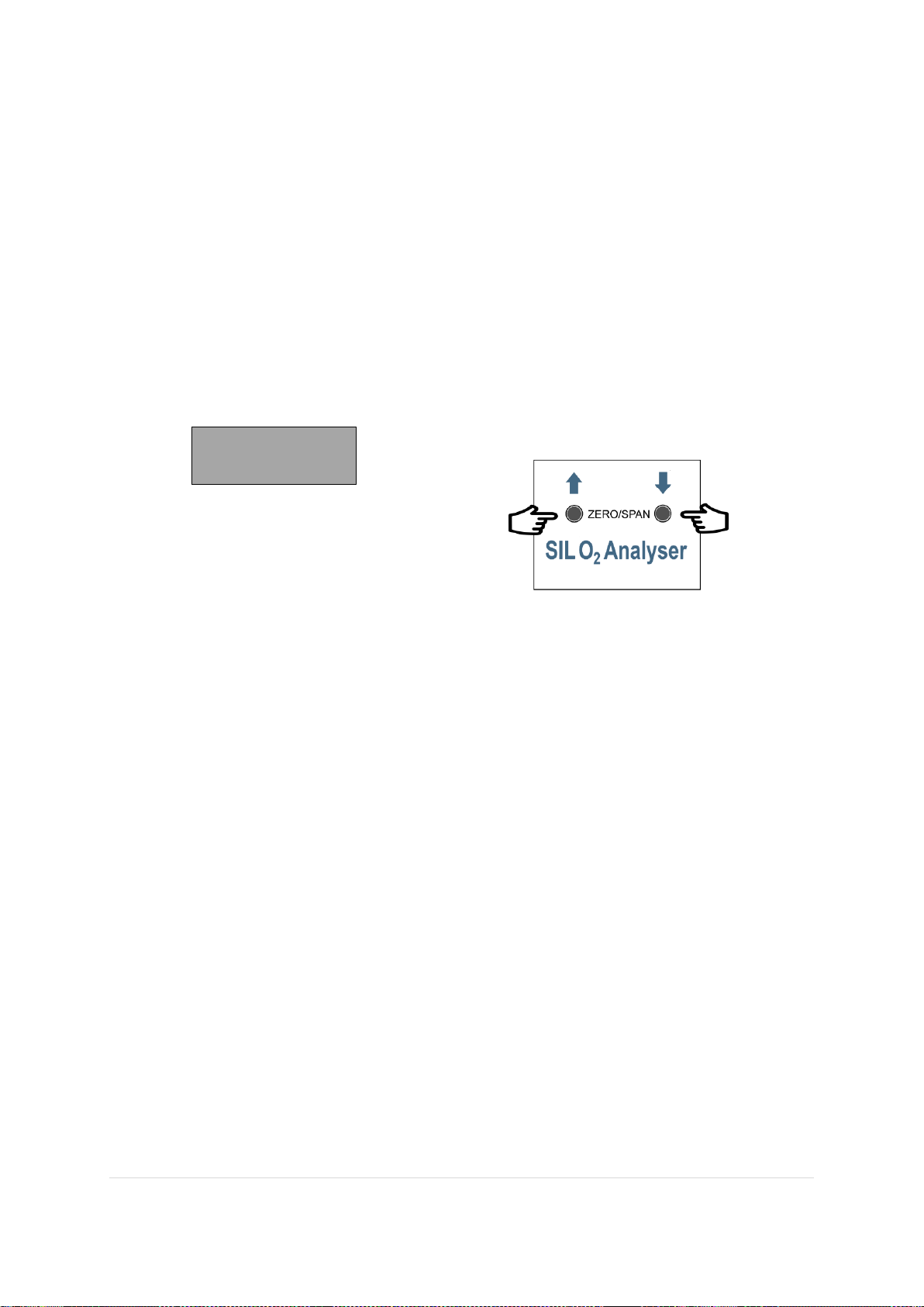
• If a zero setting is made first, then after the end of the zero operation mode, the Span mode is
automatically activated after a delay of 20 seconds.
• If A Span only calibration is required, then just press the UP or DOWN buttons individually to
increase or decrease the displayed value of oxygen to read 20.9. Note: Ensure the Sensor is in
20.9% oxygen when you do this!
• Calibration complete.
1.5.6 Alarm levels and Configuration Changes.
This is possible only with the specified remote software referred to in section 2.3.2 on page 12.
Application of changes to alarm levels and all operational parameters within the SILO2 Analyser required the
Analyser to be power cycled. A printed copy of the changed alarm levels and other parameters should be
generated by the user from the remote software and stored securely as the current record for these parameters.
The changed parameters should then be checked for correct operation by applying suitable test gases to the
Sensor connected to the Analyser.
20.90
Page 23

23 | P a g e R e v . 1 . 7 M a n u a l P a r t N o : 06- 1 8 3
I s s u e 13/ 03/ 2 0 2 4
1.6 Testing
1.6.1 Partial Proof Testing
Details on how to arrive at proof test intervals for a given application are contained within the relevant
Ntron SILO2 Safety manual.
For SIL 2 applications:
Recommended partial proof test interval = once every two weeks(fortnightly).
Recalibration interval = once every 3 months for a yearly maximum sensor drift value of 8%.
Typically, a Partial Proof test would reveal if any calibration adjustment is necessary. It is recommended that
before each operation period, this test is made. This consists of applying 20.9% O2 to the Sensor and observing
the response at the SIL O2 Analyser display and/or 4-20mA output to the users control system. The response
should be within the stated drift values (See the sensor specification table on page 28). These maximum
allowable limit values are 20.27% O2 lower limit and 21.52% O2 upper limit. (See also the Specifications
Section of this manual)
If the maximun allowable sensor drift value is exceeded within the determined partial proof test interval the
Sensor should be considered as having failed and should be replaced. (See also section 2.4.2 of this manual)
1.6.2 Full Proof Testing
In addition to the Partial Proof Testing described in the calibration section previously, A periodic Full Proof
Test of the Ntron SIL 2 Product must be undertaken. Typically, this will be once per year. This may coincide
with Partial Proof testing of be a separate test schedule. The Proof Test interval can be determined by the user
depending on the Safety Integrated System requirements but should not exceed the maximum period as detailed
in the relevant Ntron SILO2 Safety Manual document noted on page 5 of this document.
A Full Proof Test will consist of checking the calibration, sensor response and operational tests of the SIL
Analyser output relay devices as described in the Alarm Level and Trip Function testing sections below.
1.6.3 Alarm Level Testing
The alarm level settings values (setpoints) of relays 1 and 2 and operational configuration
(Closed/Open/Rising/falling) should be securely stored and available for consulting for this test.
Select suitable test gases to apply to the connected Sensor to cause the alarm level relays to operate at their
applicable setpoints. The gas input should be applied to as to increase and then decrease (or vice-versa) the
measured gas level on both sides of the alarm level setpoint. The operation of the relays may be monitored by
the host SIS or by disconnecting the wiring to the host SIS if safe to do so and connecting a test lamp or
resistance meter across the respective relay contacts and noting the ‘open’ and ‘closed’ states of the relay. The
4-20mA output if utilized, may also be monitored to observe the change in signal level as the applied Oxygen
increases and decrease. This monitoring may take place by the host SIS or by connecting a milliamp measuring
device across the Analyser analogue output terminals. See also trip function testing below for analogue output
response.
Page 24

24 | P a g e R e v . 1 . 7 M a n u a l P a r t N o : 06- 1 8 3
I s s u e 13/ 03/ 2 0 2 4
1.6.4 Trip Function Testing
Relay 3 is the trip relay for the Analyser, monitoring the correct operation of internal control processors and
inputs and outputs of the Analyser. It also responds to a detected wire break or disconnection of the Sensor input
and analogue output.
To test this function, whilst the Analyser is operational, disconnect the Sensor. After a time period of up to 30
seconds, the RED trip indicator should illuminate and relay 3 should de-energise to open circuit condition. This
can be verified following the procedure for checking the alarm level relays described above. The 4-20 mA
analogue output will reach a constant high value of 22.0 mA. At the same time, the setpoint relays RL1 and RL2
will be deactivated.
Reconnect the Sensor and wait for up to 30 seconds for the RED trip indicator to extinguish and for relay 3 to
re-energise.
To test the response to a break or disconnection of the Analyser analogue output, disconnect the analogue wiring
from the Analyser. (One wire will suffice) The Analyser display should go blank, and the RED trip indicator
should illuminate.
Reconnect the wiring. The Analyser display should return immediately and after a period of up to 30 seconds,
the RED trip indicator should extinguish.
End of routine testing.
2. Operational safety and maintenance instructions.
If it is assumed that safe operation is no longer possible, the device must be taken out of service and protected
against accidental use. The reasons can be:
visible damage to the device
failure of the electrical function
long shelf life at temperatures above 85 ° C
Transport damage
Before the device can be put back into service, a professional routine check must be carried out in accordance
with DIN EN 61010, part. 1. This examination must be carried out by the manufacturer. Repair work on Ex devices
may only be carried out in accordance with § 9 of Ex. (Elex V).
2.1 Fault conditions-defined special state.
The SIlO2 Analyser will respond to an internal diagnostic fault or an input /output connection fault by entering a
‘fault’ (or trip) state. This is the defined special state and consists of the main diagnostic relay RL3 deenergising (associated contact elements open circuit) and the RED ‘Error’ indicator illuminating.
This fault (or trip) state is not latching. When a fault condition is repaired, the relay RL3 and the red fault indicator
will return to their "healthy" or "operational" state after a period of up to 30 seconds following an automatic
internal cyclic check.
Page 25
25 | P a g e R e v . 1 . 7 M a n u a l P a r t N o : 06- 1 8 3
I s s u e 13/ 03/ 2 0 2 4
2.2 Analyser Internal Diagnostic fault
A number of internal faults in the SIL O2 analyzer generate a fault output and interrupt the safety circuit. In some
cases, cycling the power supply of the SIL O2 analyzer may be sufficient to remedy the problem. Otherwise,
please contact Ntron for assistance.
2.3 Troubleshooting
Possible Faults and their solutions
The following possible conditions are applicable to a system (Sil Analyser and Sensor) already installed
and commissioned. Some conditions below may also be applied to new systems not yet commissioned.
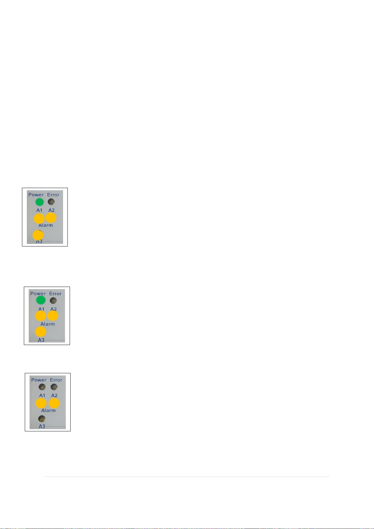
• Action: Performing a Zero calibration when the Oxygen Sensor is in ambient air.
Problem: An incorrect Zero level input to the Analyser will result in an overrange fault. This can
occur if a Zero calibration is performed when the Sensor is in ambient air. If this occurs, the Red fault
LED will illuminate, and the Analyser display and Analogue output will read an over-range value.
The Alarm level LED’s may also illuminate. This may also occur if a genuine overrange event takes
place, with gas containing more than 25% O2 being applied. (25%O2 displayed)
Solution: re-calibrate with Nitrogen gas (Zero) and then re-calibrate at the Span point of 20.9%.
• Action: Powering on the Analyser with no sensor connected or a wire break to the sensor.
Problem: If the sensor is disconnected, this would ordinarily cause relays R1, R2 and R3 to de-
energise. Analyser display and Analogue output will read a fault value. (28% O2 displayed and 22mA
output)
Solution: Check Sensor wiring and connect the sensor to the Analyser. After approximately 30
seconds, the Analyser will reset, and the Red LED should extinguish.
• Action: Unable to perform a Span calibration.
Problem: The Analyser cannot be adjusted to display 20.9% O2 during Span calibration.
Solution: The Sensor may be approaching end of life or has been damaged and cannot generate
sufficient output. Replace the sensor!
Alarm level LED’s may or may not be illuminated depending on configuration.
Page 26
26 | P a g e R e v . 1 . 7 M a n u a l P a r t N o : 06- 1 8 3
I s s u e 13/ 03/ 2 0 2 4
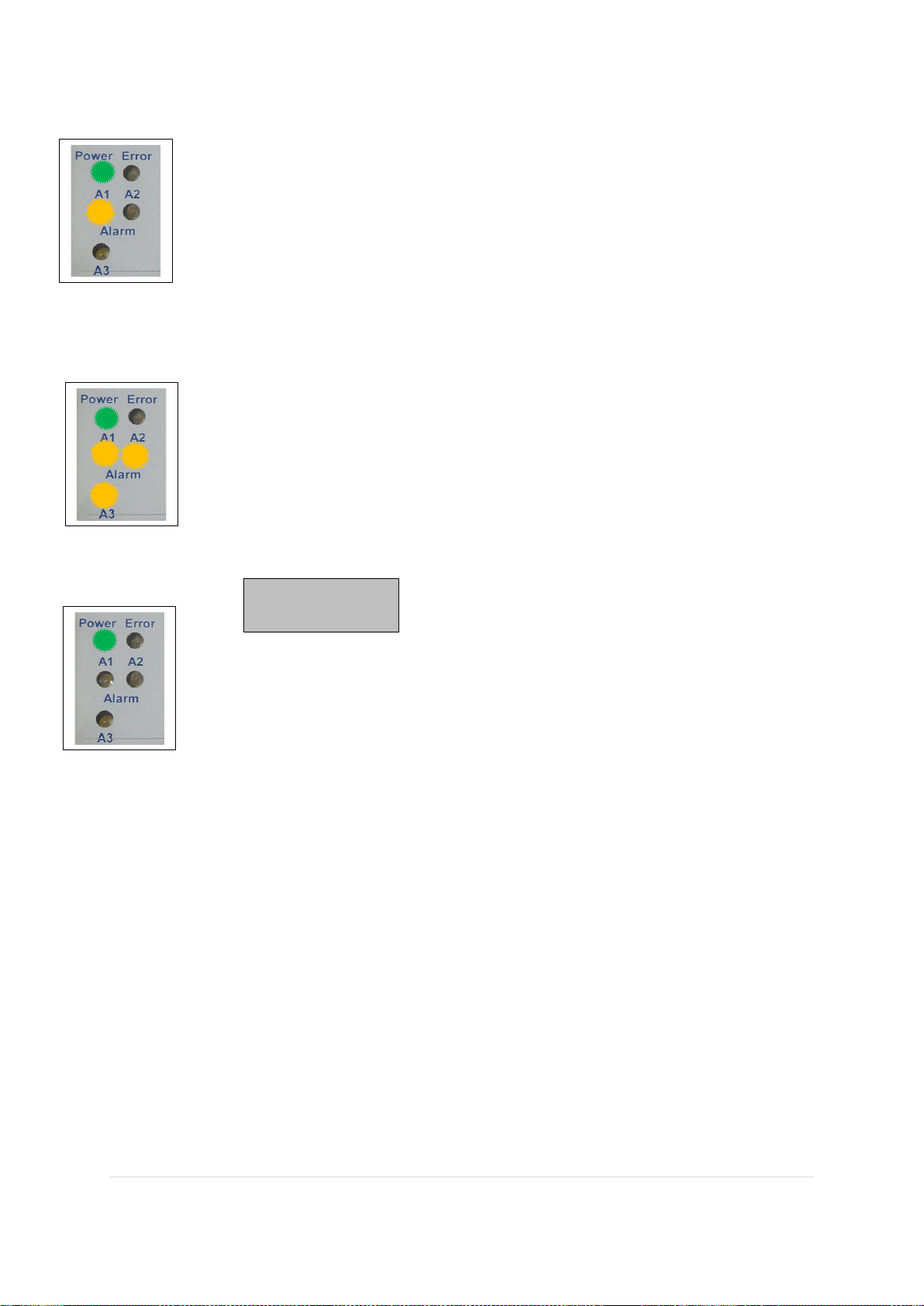
• Action: Alarm Level LED’s (Yellow) illuminated.
Problem: Alarm level LED’s illuminated.
Solution: Genuine Oxygen level alarm event.
Incorrect sample gas levels being applied to the Sensor or incorrect alarm level settings are configured
within the Analyser. If this is not expected, then check sample gas with independent instrument
gas/and/or re-configure Analyser Alarm setpoints. This will require interface with PC based software.
• Action: Red Fault LED illuminated when none of the above conditions are present.
Problem: Analyser in fault condition. Analyser display and Analogue output will read a fault value.
(28% O2 displayed and 22mA)
Solution: Internal Analyser electronics or programming fault. Try Power On/Off cycle to reset.
If fault does not clear, then seek further assistance.
Problem: No Analyser display (Blank)
Solution: Analogue output circuit is broken or interrupted. Investigate and repair.
2.3.1 Possible Sensor Faults
Applicable to all sensor types (OC-25, OC-26, OC-200)
Problem:. SIL O2 Analyser will not calibrate (Cannot be set to 20.9%)
Solution: Sensor is at end of life. Sensor has been wetted or contaminated. The Sensor output signal can be
checked at the SIL O2 Analyser terminals 14 and 16. See specification section for details of a healthy
output signal.
Problem:. SIL O2 Analyser reads Zero (0.00)
Solution: Actual low Oxygen measurement. Sensor wires have been shorted together, damaging the Sensor.
Verify the Oxygen level by other means. Check the Sensor output signal. Replace Sensor as necessary.
Page 27

27 | P a g e R e v . 1 . 7 M a n u a l P a r t N o : 06- 1 8 3
I s s u e 13/ 03/ 2 0 2 4
General Maintenance
Establish a periodic checking and maintenance routine in line with the requirements for Safety Instrumented
Systems. See the Ntron SIL O2 Analyser Technical and Safety manual for further details.
The SIL O2 Analyser requires little physical maintenance. The user Enclosure into which it is housed
should provide protection against a buildup of dust or other contaminants on the surface of the SIL O2
Analyser housing. If such contaminants are seen during regular inspection, such can be removed by gentle
suction device or by wiping with a damp but not wet, cloth. The ingress of such contaminants should be
investigated.
Ensure all wiring to the SIL O2 Analyser is secure and in good condition, paying particular attention to the
security of the connection terminals if the user enclosure is subject to vibrations.
There are no user serviceable parts within the SIL O2 Analyser. If any malfunction is detected, mechanical
or electrical, the SIL O2 Analyser should be immediately removed from service following the correct
protocols.
The Sensor used has a finite life span. The Performance of the Sensor is verified by calibration check, and
this should be performed according to the protocols required by the safety system. Replacement of the
Sensor is necessary when it does not meet the required performance levels.
During operation life, the Sensor should be kept clean of contaminants. It can be wiped with a soft damp
cloth. Observe the restrictions regarding potential static charges as detailed on the Sensor Installation
Instruction Documents found in the appendix to this manual.
When removing Sensors from their process installation for replacement or other service requirements,
observe the following points.
• Ensure any and all system shut down protocols are followed as applicable.
• Do not disconnect the Sensor from the connecting cables whilst the system is operating or is
‘Live’.
• Ensure the process being measured is shut down or the Sensor connection is isolated by any
intermediate valve mechanism if fitted.
• Always remove the Sensor connector before unscrewing the OC-25/OC-20x Sensors or
unclamping the OC-26 Sensors from their process fittings
• Block off the exposed process connection if required during the period the Sensor is disconnected.
• Protect the disconnected Sensor cable from damage during the period the Sensor is disconnected.
OC-26 and OC-26M. KF40 Flange connection. User responsibilities.
Ensure a suitable gasket is used with the KF flange adapter and clamp mechanism. Tighten sufficiently to form a
gas tight seal. Leak check prior to returning system to operation. Note: do not pressurize the Sensor.
OC-25 and OC-25M. Screw-on base connection. User responsibilities.
Ensure the sealing ‘O’ ring is fitted (supplied with each Sensor) between the sensor and Screw-on base. The
Sensor should be hand tightened only. Leak check before returning system to operation.
Apart from the Sensor, there are no user serviceable parts within this equipment. The Sensor may
only be replaced as a complete item and any such replacement may be subject to certain oversight as
required within the user’s SIS requirements.
Page 28

28 | P a g e R e v . 1 . 7 M a n u a l P a r t N o : 06- 1 8 3
I s s u e 13/ 03/ 2 0 2 4
3. Specifications
SIL O2 Analyser
Specifications-Electrical General
Supply Voltage.
24VDC Nominal. (See also safety parameter table)
Supply Power.
Maximum 1.5 Watt
Analogue Output.
4-20mA active source. 22mA Max output . Load 390 Ohm@22mA, Max
420 Ohm@20mA constant current.. See also Maximum Line Resistance
Data on page
Communications.
RS232/Com 9600bps. 1-248. Pre-made and supplied interface cable with
software required, to enable the use of this option.
Range.
0-25% Oxygen. (Note sensor range restrictions on page 25)
Relay Contact outputs
RL1/RL2
Switching voltage: 30VDC@ 1A and 125VAC@ 0.5A. Min Current
10uA DC. Min. Voltage 10mVDC. Type According to IEC 947-5-1 resp.
EN 60947) (Contacts to be protected by fuse/fuses of rating 0.6Amps
maximum.) See also Safety Parameters. Contact Material: AG Pd+10uAu.
Relay Contact outputs
RL3
Normally Closed operation when healthy and under power.
Switching voltage: 30VDC@ 1A and 125VAC@ 0.5A. Min Current
10uA DC. Min. Voltage 10mVDC. Contact Material: AG Pd+10uAu.
Digital Output (Do).
Switching parameters: <28V @<50mA, 1.4W See also Safety
Parameters.
Accuracy
<0.04% Max. <0.02% Typical of final value.
Specifications-Mechanical
Terminal /Wire Size.
Pluggable/Quick Release terminals, capacity 2.5mm
2.
Mounting.
35mm Din rail
Housing Material.
PBT
Protection Class.
IP20*
Combustibility Class.
VO according to UL
Weight.
300g
Enviromental.
Temperature: -20 to +60°C, 10-95% Humidity, no condensation.
Pressure= +/-10% of ambient.
Dimensions.
67 mm x 114.5 mm x 99 mm
Indications.
4 Digit LCD Display, Green OK led, Red Fault LED, Amber Alarm LED.
Page 29

29 | P a g e R e v . 1 . 7 M a n u a l P a r t N o : 06- 1 8 3
I s s u e 13/ 03/ 2 0 2 4
SIL O2 Analyser
Specifications-Safety Parameters
Non-intrinsically safe
circuits. (See headings
below).
The non-intrinsically safe supply circuit and the non-intrinsically safe
digital output circuit must be connected to Safety Extra-Low Voltage
(SELV) circuits. Maximum voltage Um (e.g. 250V) shall apply as a
common mode failure voltage (in respect to PA/PE) only. As a differential
mode failure voltage, the rated voltage has to be applied.
Supply circuit voltage.
Terminals 3 and 4. DC 19 to 30V; AC 18 to 28V;
Maximum Common Mode voltage AC/DC Um = 250V
Front Com Socket rated
voltage and current.
DC 6V; 100mA
Maximum voltage AC/DC Um = 48V
Relay contacts 1,2; 5,6;
9,10.
Switching Voltage DC 30 V; AC 125 V
Switching Current DC 1A; AC 0.5A
Maximum Voltage AC/DC 125 V
Digital Output 7,8 rated
voltage and current.
(SELV) DC 28V; 50mA
Maximum Common Mode voltage AC/DC Um = 125V
Analogue output 11,12,
rated voltage and current.
DC 20 V; 50mA
Maximum voltage Um=125 V
Intrinsically Safe Circuits.
(See headings below)
Applicable to the mV input circuit terminals 14 and 16 (Blue terminals)
Input Safety Parameters.
voltage Uo DC 6 V
current intensity Io 1.0 mA
power Po 1.5 mW
max. outer inductivity Lo 1000 mH
max. outer capacity Co 10 μF
Internal Capacitance Ci Max. 0.2uF
Internal Inductance Li Max Negligable
External I.S. Circuit
connection.
Maximum Input voltage presented to SILO2 Ui = DC 1 V
Galvanic Separation
Input/Output/Supply
300 Veff (rated insulation voltage, overvoltage category II,
Contamination. level 2, safe separation as per EN 61010, EN
50178); 2.5 kV AC testing voltage (50 Hz, 1 min.);
nput/output: 375 V (peak value as per EN 60079-11)
Input/supply: 375 V (peak value as per EN 60079-11)
Sensor Cable Maximum
allowable values.
Max. capacity: 200 nF (from wire to wire) ; Max. inductance:
500 μH ; Max. loop resistance: 500 Ω
Page 30
30 | P a g e R e v . 1 . 7 M a n u a l P a r t N o : 06- 1 8 3
I s s u e 13/ 03/ 2 0 2 4
SIL O2 Analyser
Certification and Standards
Models.
SILO2 Analyser, Prt No.‘s 01-758, 06-205
IECEx Marking.
[Ex ia Ga] IIC and [Ex ia Da] IIIC
ATEX Marking.
II (1) G [Ex ia Ga] and II (1) D [Ex ia Da] IIIC
IECEx Certificate No.
IECEx BVS 24.####X
ATEX Certificate No.
BVS 24 ATEX E ###X
Appiled Ex Standards
IECEx.
IEC 60079-0:2017 Ed.7 and IEC 60079-11:2011 Ed.6
Applied Standards
ATEX.
EN IEC 60079-0:2018 and EN 60079-11:2012
Applied Standards EMC
EN 61326-3-2:2008, EN 55011:2009
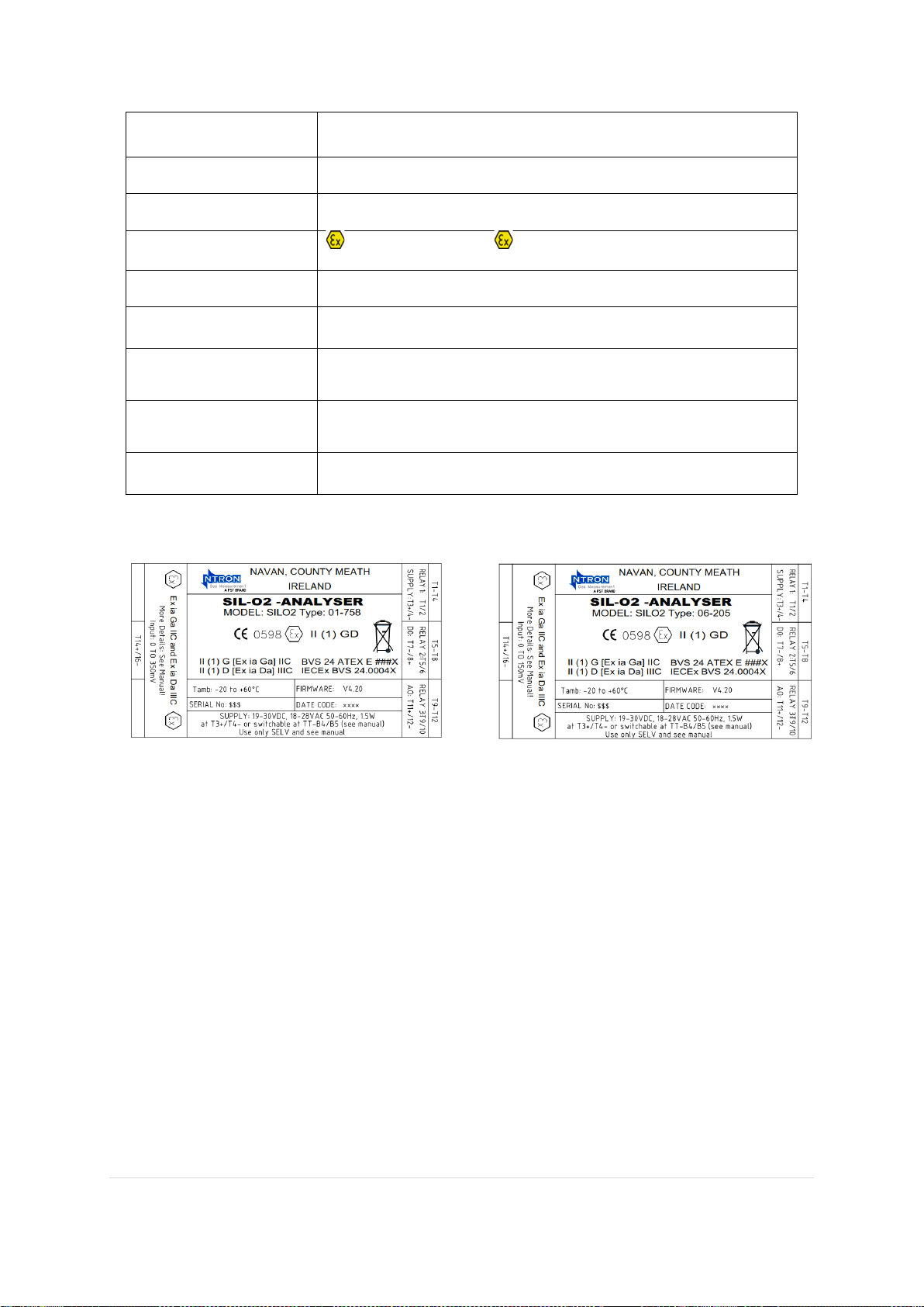
SIL O2 Analyser Labelling
For Sensor models OC-25 and OC-26 For Sensor models OC-20x (Oxyprobe)
Page 31

31 | P a g e R e v . 1 . 7 M a n u a l P a r t N o : 06- 1 8 3
I s s u e 13/ 03/ 2 0 2 4
Oxygen Sensor
Specifications-Electrical
Models.
OC-25, (and suffix M) OC-26 (and suffix M) OC-20x series(x=0, 1, 2 etc)
Range.
0-25% Oxygen
Signal Output.
300-375mV in Air OC25, OC-26. 135-160mV in Air OC-20x
Technology/Lifespan.
Electrochemical Solid State Long Life / 3 Years application dependant.
Shelf life.
OC-25, (and suffix M) OC-26 (and suffix M) = 12 Months from date of
manufacture
OC-20x (Oxyprobe)= 6 Months from date of manufacture.
Long term Sensor Drift.
Maximum operational <8% per year and <15% per 3 years for all models.
Maximum Allowable
sensor drift.
+/- 2.5% of upper limit of the measurement range(25%) which is +/-
0.625% O2.
Response time T90
<20 seconds nominal. (For safety operational purposes the maximum
allowable time is <45 seconds) See relevant Ntron Safety manual.
Connection.
Circular Pluggable IP67 Connector with cable to specified length.
Oxygen Sensor
Specifications-Mechanical
Dimensions OC-25.
100mm High x 50mm Diameter
Dimensions OC-26.
75mm High x 55 Diameter (KF40)
Dimensions OC-20x.
Variable length to order, typically 200mm long x 12mm Diameter probe.
Max. Diameter is 30mm.
Protection Class.
IP67 When inserted into process fitting with Connector fitted*.
Process Connection.
OC-25 =Ntron Sensor base; OC-26 = KF40 Flange, OC-20x = Probe
Holder mechanism or Bushing
Weight.
OC-25= 250g; OC-26=150g, OC-20x=180g approx.
Suffix M models: OC-25 = 490g; OC-26 = 480g approx.
Environmental.
Rated operational Temperature: -20 to +50°C, 10-95% Relative Humidity,
no condensation.
Operational Pressure and
flow rates per process
connection type.
All sensor types are designed for operation at ambient pressure +/-10%.
Operation outside of this range may result in erroneous Sensor output or
damage to the Sensor. The sample Gas delivery system being used should
provide for the above conditions. Gas flow rates should not pressurise the
Sensor. An atmospheric level vent pressure is recommended.
Flow Through connection:-small bore (6mm) tube. 250mLPM
Tri-clamp/screwed bush connection: (Large dia pipe or vessel) up to
1LPM typical. Very fast flows of gas may cause turbulance or
pressurising of the sensor. Pipe Tee legs for Tri-clamp connections should
not be longer than required to prevent gas entrapment.
Page 32

32 | P a g e R e v . 1 . 7 M a n u a l P a r t N o : 06- 1 8 3
I s s u e 13/ 03/ 2 0 2 4
*Note. IP ratings stated do not necessarily imply that the equipment will detect gas during and after
exposure to the conditions applicable to the stated IP level.
A regular maintenance routine should be established which considers the operation at the rated IP level.
Generally, this will be related to the local operating conditions.
Additional protective measures may need to be taken, such as covers, enclosures etc to meet the
operational specifications of the equipment. Any such additional measures should not degrade or
otherwise interfere with the Ex-certification of the product.
Oxygen Sensor
Specifications-Safety Parameters
Limit. of Use. All models.
Not to be used in oxygen enriched atmosphers greater than 21% oxygen.
Essential Requirements.
Metal bodied models (suffix M) must be earthed. Plastic bodied models
must be protected from situations that couls cause a build up of a static
charge. They must also not be installed in locations with fast moving dust
laden air/gas or non-conductive fluids.
Intrinsically Safe Sensor
Input Connection
Parameters.
OC-25, OC-26 and OC-26
suffix M,
Oxyprobe OC-20x.
voltage Uo DC 12 V
current intensity Io 120 mA
power Po 0.55 W
max. outer inductivity Lo 0 mH
max. outer capacity Co 1.2 μF
Intrinsically Safe Sensor
Input Connection
Parameters.
OC-25 suffix M
voltage Uo DC 12 V
current intensity Io 120 mA
power Po 0.55 W
max. outer inductivity Lo 24.69 uH
max. outer capacity Co 1.2 μF
Rated ambient
temperature range
-20 to +55°C
Page 33
33 | P a g e R e v . 1 . 7 M a n u a l P a r t N o : 06- 1 8 3
I s s u e 13/ 03/ 2 0 2 4
SIL Capability of the Analyser and Sensor System
Standards Applied
IEC 61508:2010
Functional Safety of
Electrical/Electronic/Programmable
Electronic Safety-Related Systems
IEC 61511:2004
Functional Safety of
Electrical/Electronic/Programmable
Electronic Safety-Related Systems
EN 50104:2019
Electrical equipment for the detection and
measurement of oxygen — Performance
requirements and test methods
Oxygen Sensor
Certification and Standards
Models
OC-25, OC-26, OC-20x
IECEx Marking
[Ex ia Ga] IIC and [Ex ia Da] IIIC
ATEX Marking
II 1 GD Ex ia IIC T6 Ga(-20°C≤Ta≤+55°C)
Ex ia IIIC T90°C Da( -20°C≤Ta≤+55°C)
IECEx Certificate No.
IECEx BAS 09.0148X
ATEX Certificate No.
BAS02ATEX1230X
Appiled Ex Standards
IECEx
IEC 60079-0:2017 and IEC 60079-11:2011
Applied Standards ATEX
EN IEC 60079-0:2018 and EN 60079-11:2012
Page 34

34 | P a g e R e v . 1 . 7 M a n u a l P a r t N o : 06- 1 8 3
I s s u e 13/ 03/ 2 0 2 4
4. Appendices
• SIL O2 Analyser CE, ATEX and IECEx Certificates
• Sensor CE, ATEX and IECEx Certificates
Page 35

35 | P a g e R e v . 1 . 7 M a n u a l P a r t N o : 06- 1 8 3
I s s u e 13/ 03/ 2 0 2 4
Ntron Ltd.
Mullaghboy Industrial Estate,
Navan, County Meath, Ireland.
00353 46 9071333
www.ntron.com
 Loading...