

Page 1
transducer quality strain gage
50-CONDUCTORS
LIMB WIDTH 0.026 mm
GAP WIDTH 0.022 mm
AGL 0.75 mm
19.2 mm
19.2 mm
25.4 mm
full bridge linear
diaphragm pattern
OMEGA offers transducer quality, linear
diaphragm pattern strain gages for use
in pressure transducer designs. These
patterns have 4 strain gages mounted
onto a single carrier. The strain gages
in the center will go into tension, and the
outer 2 will go into compression. In the
pressure transducer design, a diaphragm
is clamped around the outer edge, and
subjected to a uniform pressure. Near
the center of the diaphragm the radial
and tangential strains will be positive,
and will be nearly equal. The radial strain
decreases and becomes negative as
you move away from the center toward
the outer edge. Midway between the
center and the outer edge the strain is at
its lowest and the leads/Solder Pads are
located in this low stress area. In these
patterns, there are 2 half-bridges.
Each half-bridge has a common lead/
Solder Pads.
To Order
GAGE PATTERN
Leads not shown
actual size,
10.2 mm
actual size,
actual size,
actual size,
actual size,
Shown
Shown
13.5 mm
Shown
19.2 mm
Shown
19.2 mm
Shown
25.4 mm
DISCOUNT SCHEDULE
1 to 10 pkgs .................. Net
11 to 24 pkgs ..................5%
25 to 49 pkgs .................10%
50 and up and OEM ..Consult Factory
MODEL NO.
Pkg of 5
SGT-9/350-LD11
SGT-9/350-LD13
SGT-9/350-LD41
SGT-9/350-LD43
SGT-12/350-LD11
SGT-12/350-LD13
SGT-12/350-LD41
SGT-12/350-LD43
SGT-18/350-LD11
SGT-18/350-LD13
SGT-18/350-LD41
SGT-18/350-LD43
SGT-18/1000-LD11
SGT-18/1000-LD13
SGT-18/1000-LD41
SGT-18/1000-LD43
SGT-24/350-LD11
SGT-24/350-LD13
SGT-24/350-LD41
SGT-24/350-LD43
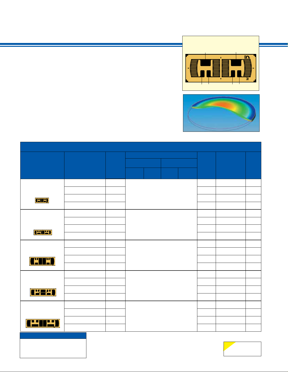
One of the patterns has been enlarged
to show the detail. The strain gages and
Gage 2-
terminal pads have been numbered and
labeled. The corners of the Wheatstone
bridge have been left open for the addition
of zero temperature compensation
resistors, and zero balance compensation
resistors if required. Several sizes
are available.
-S
SGT-9/350-LD** can be used for a
0.4" diameter diaphragm.
SGT-12/350-LD** can be used for a
0.5" diameter diaphragm.
SGT-18/350-LD** and SGT-18/1000-LD**
can be used for 0.75 to 0.8" diameter
diaphragms.
SGT-24/350-LD** can be used for
1" diameter diaphragms.
NOM.
RESISTANCE
(Ω)
350
350 6.5
350 4.5
GRID CARRIER
A B C D
0.8 2.6 10.2 4.0
(0.031) (0.102) (0.402) (0.157)
Full-bridge, 10.2 mm (0.4")
diameter diaphragm
350 Ω
DIMENSIONS mm (inch)
†
MAX V*
(Vrms)
4.5
350 6.5
350
350 7.5
350 5.5
1.0 2.6 13.5 4.0
(0.039) (0.102) (0.534) (0.157)
Full-bridge, 13.5 mm (0.5")
diameter diaphragm
350 Ω
5.5
350 7.5
350
350 14
350 10
1.8 5.0 19.2 6.4
(0.071) (0.197) (0.756) (0.252)
Full-bridge, 19.2 mm (0.75 to 0.8")
diameter diaphragm
350 Ω
10
350 14
1000
1000 13
1000 9
1000 13
350
350 14
350 10
1.8 4.0 19.2 5.5
(0.071) (0.157) (0.756) (0.217)
Full-bridge, 19.2 mm (0.75 to 0.8")
diameter diaphragm, higher
resistance, reduced heat generation
1000 Ω
1.8 5.0 25.4 6.4
(0.071) (0.197) (1) (0.252)
Full-bridge, 25.4 mm (1")
diameter diaphragm
350 Ω
10
350 14
† For dimensions key, visit us online.
Maximum permitted bridge energizing voltage (Vrms).
*
Note: For strain gage accessories, visit us online.
Ordering Example: SGT-9/350-LD11, package of 5, full bridge linear
diaphragm pattern.
LD11, LD13, LD41 or LD43.
**
E-39
-Exc
+S
9
Gage 3+
+Exc
Gage 1+
-S
+S
TERMINATION
Ribbon Leads
Ribbon Leads
Solder Pads
Solder Pads
Ribbon Leads
Ribbon Leads
Solder Pads
Solder Pads
Ribbon Leads
Ribbon Leads
Solder Pads
Solder Pads
Ribbon Leads
Ribbon Leads
Solder Pads
Solder Pads
Ribbon Leads
Ribbon Leads
Solder Pads
Solder Pads
NOTE
ST = Steel
AL = Aluminum
Gage 4-
TEMP
COMP
ST
AL
ST
AL
ST
AL
ST
AL
ST
AL
ST
AL
ST
AL
ST
AL
ST
AL
ST
AL
Page 2
8.4 mm
SGT-8/350-LD11
5.5 mm
62-CONDUCTORS
LIMB 0.036 mm
GAP 0.030 mm
AGL 1.1 mm
transducer quality
8.4 mm
8.4 mm
12.25 mm
strain gage
1/2 bridge linear diaphragm
The following types of linear diaphragm
strain gages can be used when
the bonding area is larger than the
diaphragm diameter. For example, if a
body has a flat surface with a diameter
of 1" onto which the strain gage is to
be bonded, but a 0.5" diameter hole is
drilled through the body leaving just a
thin layer of material, then this thin
0.5" diameter is the diaphragm. So
the strain gage grids are located above
the thin high stress area and the leads/
solder pads are over the solid part of the
body in the low stress area. This linear
diaphragm pattern has 2 strain gages
mounted onto a single carrier. These
types are used in pairs on a
0.5" diameter diaphragm. The strain
gage closer to center will go into
tension, and the outer gage will go into
compression. Near the center of the
diaphragm the radial and tangential
strains will be positive, and will be nearly
equal. The radial strain decreases and
becomes negative as you move away
To Order
GAGE PATTERN
Leads not shown
actual size,
actual size,
Shown
8.4 mm
Shown
8.4 mm
MODEL NO.
Pkg of 5
SGT-8/350-LD11
SGT-8/350-LD13
SGT-8/350-LD41
SGT-8/350-LD43
SGT-8/500-LD11
SGT-8/500-LD13
SGT-8/500-LD41
SGT-8/500-LD43
from the center toward the outer edge
of the diaphragm. The leads/solder
pads are in the low stress area over
thicker material. In this pattern, each
carrier piece has one half-bridge with a
common lead/solder pad. The corners
of the Wheatstone bridge have been
2 half-bridges mounted onto one carrier
piece, which can be used on a 0.28”
diameter diaphragm again where the
bonding area is larger. The grids are
placed, centered over the diaphragm,
and the leads/solder pads are over solid
material in a low stress area.
left open for the addition of
zero temperature
compensation resistors, and
zero balance compensation
resistors, if required.
SGT-8/350-LD** and
SGT/500-LD** are used
in pairs on a 0.5" diameter
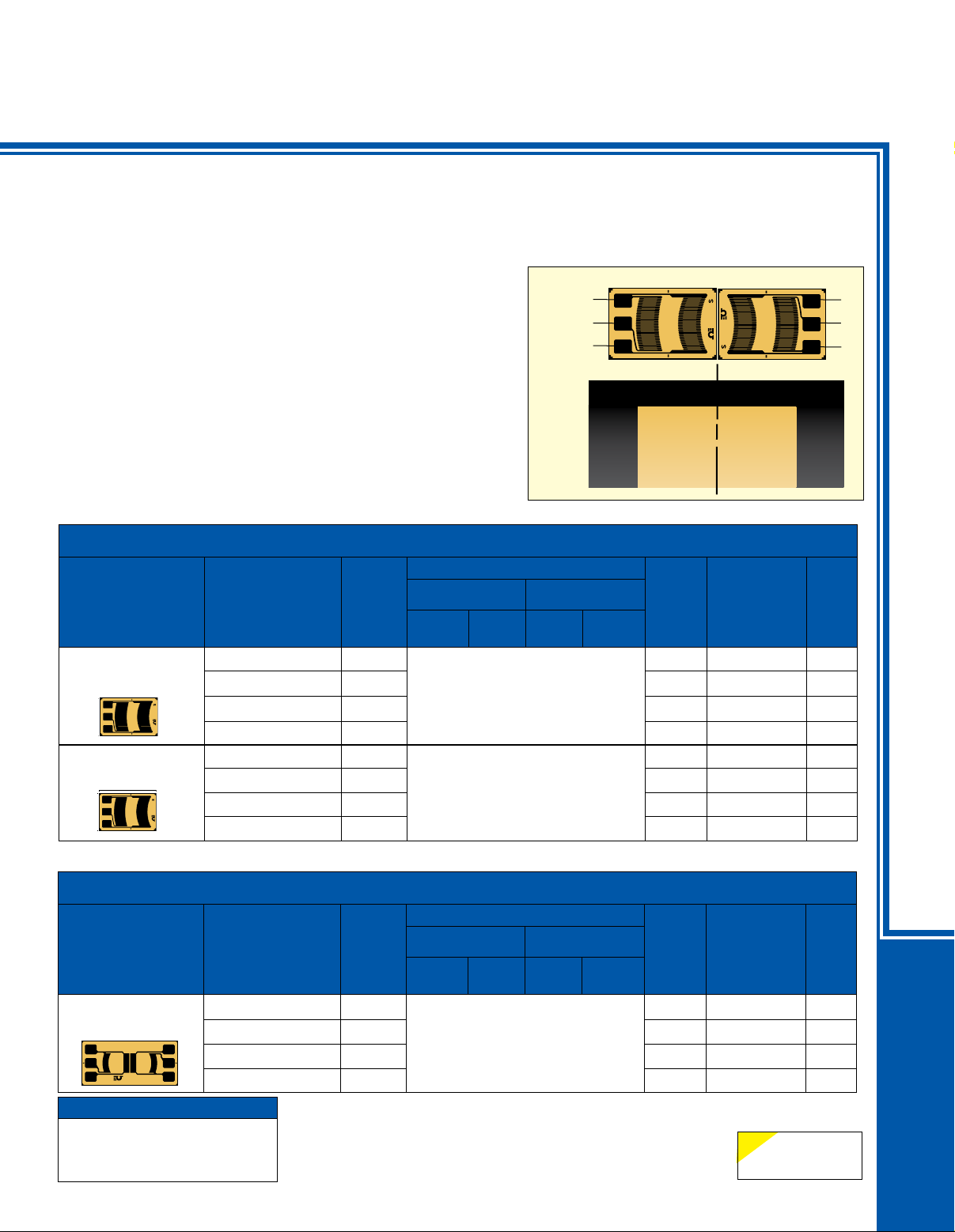
diaphragm. Below we show
Top View
-E
-S
+S
Edge view showing placement
a diagram with 2 pieces of
the SGT-8/350-LD**, shown
as they might be positioned
on a 0.5" diameter diaphragm.
The strain gages have been
numbered and labeled.
Also available is the
SGT-7/350-LD** which offers
NOM.
RESISTANCE
(Ω)
350
350 10
350 7
350 10
500
500 11
500 75
500 11
GRID CARRIER
A B C D
1.1 4.3 8.4 5.5
(0.043) (0.169) (0.331) (0.217)
Half-bridge, used in pairs, 13 mm
(0.5") diameter diaphragm
350 Ω
1.2 4.3 8.4 5.5
(0.047) (0.169) (0.331) (0.217)
Half-bridge, used in pairs, 13 mm
(0.5") diameter diaphragm
nominal resistance
500 Ω
DIMENSIONS mm (inch)
†
2- 4-3+ 1+
Diaphragm
MAX V*
(Vrms)
7
TERMINATION
Ribbon Leads
Ribbon Leads
Solder Pads
Solder Pads
Ribbon Leads
7.5
Ribbon Leads
Solder Pads
Solder Pads
TEMP
COMP
ST
AL
ST
AL
ST
AL
ST
AL
-S
+S
+E
STRAIN GAGES
full bridge linear diaphragm
To Order
GAGE PATTERN
Leads not shown
actual size,
Shown
12.3 mm
DISCOUNT SCHEDULE
1 to 10 pkgs .................. Net
11 to 24 pkgs ..................5%
25 to 49 pkgs .................10%
50 and up and OEM ..Consult Factory
MODEL NO.
Pkg of 5
SGT-7/350-LD11
SGT-7/350-LD13
SGT-7/350-LD41
SGT-7/350-LD43
NOM.
RESIS-
TANCE
(Ω)
350
350 5
350 3.5
350 5
† For dimensions key, visit us online.
Maximum permitted bridge energizing voltage (Vrms).
*
Note: For strain gage accessories, visit us online.
Ordering Example: SGT-8/350-LD11, package of 5, half bridge linear
diaphragm pattern.
GRID CARRIER
A B C D
0.5 2.5 12.3 5.8
(0.02) (0.098) (0.484) (0.228)
Full-bridge, 7 mm (0.28")
diameter diaphragm
350 Ω
DIMENSIONS mm (inch)
†
MAX V*
(Vrms)
3.5
LD11, LD13, LD41 or LD43.
**
E-40
TERMINATION
Ribbon Leads
Ribbon Leads
Solder Pads
Solder Pads
NOTE
ST = Steel
AL = Aluminum
E
TEMP
COMP
ST
AL
ST
AL
 Loading...