

Page 1
transducer quality strain gage
SGT-3E/350-FB11_13_41_43
6.8 mm
20-CONDUCTORS
LIMB WIDTH 0.034 mm
GAP WIDTH 0.030 mm
SGT-3/1K-FB11_13_41_43
4.9 mm
32-CONDUCTORS
LIMB WIDTH 0.024 mm
GAP WIDTH 0.024 mm
SGT-3E/350-FB11_13_41_43
6.8 mm
20-CONDUCTORS
LIMB WIDTH 0.034 mm
GAP WIDTH 0.030 mm
SGT-3F/350-FB11_13_41_43
6.8 mm
20-CONDUCTORS
LIMB WIDTH 0.034 mm
GAP WISDTH 0.030 mm
SGT-3/1K-FB11_13_41_43
4.9 mm
32-CONDUCTORS
LIMB WIDTH 0.024 mm
GAP WIDTH 0.024 mm
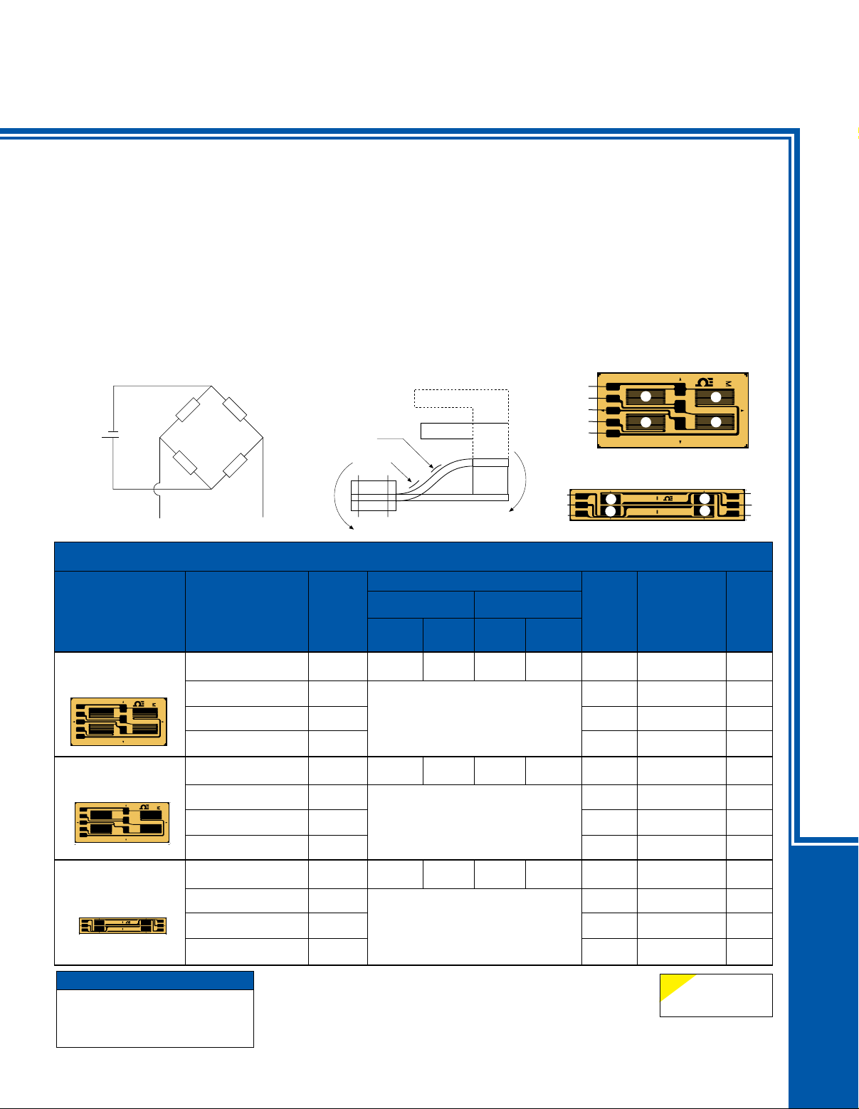
Full WHeatstOne Bridge, reversed-Bending Beam Or
cOntraFlexure Beam all grids in tHe same directiOn
Design and build your own transducers.
These full bridge strain gages might
be used to design transducers for
beams that have a contraflexure point.
Contraflexure is defined as a point in
a structure where bending occurs in
opposite directions. This may also be
described as a reversed bending beam,
or a double bending beam. The 4 grids
are linear, all in the same direction.
Look up the modulus of elasticity and
the yield strength of your material, and
design the spring element so that you
will be working in the linear portion of
the stress-strain curve. For best results
use stainless steel or aluminum and
match the strain gage temperature
+ Exc
V
IN
REGULATED
DC
- Exc
Wheatstone Bridge
1
2
- Sig
4
+
–
–
+
3
V
OUT
To Order
GAGE PATTERN
Leads not shown
Shown smaller
than actual size,
Shown smaller
than actual size,
Shown smaller
than actual size,
13.8 mm
15..9 mm
28 mm
DISCOUNT SCHEDULE
1 to 10 pkgs .................. Net
11 to 24 pkgs ..................5%
25 to 49 pkgs .................10%
50 and up and OEM ..Consult Factory
MODEL NO.
Pkg of 5
SGT-3E/350-FB11
SGT-3E/350-FB13
SGT-3E/350-FB41
SGT-3E/350-FB43
SGT-3F/350-FB11
SGT-3F/350-FB13
SGT-3F/350-FB41
SGT-3F/350-FB43
SGT-3/1000-FB11
SGT-3/1000-FB13
SGT-3/1000-FB41
SGT-3/1000-FB43
characteristics. You may use these full
bridge strain gages for bending strain
applications where only one side of
the beam is available for strain gage
installation. These gages are easy to
work with as the carrier piece has all
4 strain gages for fast and easy
installation. Having one carrier with
multiple strain gages offers several
advantages. Alignment of the 4 strain
gages with respect to each other
is already done. Some of the strain
gages share common ribbon leads
or Solder Padss which saves wiring
steps and valuable time. The corners
of the Wheatstone bridge at the signal
sensor performance can be tested
and improved. Zero temperature
compensation resistors and zero
balance compensation resistors can
be easily added into the open corners
of the Wheatstone bridge circuit. An
extra bondable terminal pad can be
placed at the open corner so that the
appropriate resistors can be wired in.
Or you can simply connect your 4 leads
(+Excitation, -Excitation, +Signal,
-Signal) and jumper the signal leads
together as needed to complete the
Wheatstone bridge. Power up your
transducer, and calibrate it with a known
applied load.
output have been left open so that
+Exc
+Sig
-Exc
-Sig
-Sig
-Exc
+Sig
†
6.8
(0.268)
6.8
(0.268)
4.9
(0.193)
-Sig
MAX V*
(Vrms)
7.5
7.5
+ Sig
TENSION
COMPRESSION
DIMENSIONS mm (inch)
NOM.
RESISTANCE
(Ω)
350
350
350 7.5
350 11
350
350
350 7.5
350 11
1000
1000
GRID CARRIER
A B C D
3.2
(0.126)
1.5
(0.059)
13.8
(0.543)
Full bridge pattern for double
bending beam, center line spacing
6.35 mm (0.25")
350 Ω
3.2
(0.126)
1.5
(0.059)
15.9
(0.626)
Full bridge pattern for double
bending beam, center line spacing
8.38 mm (0.33")
350 Ω
3.0
(0.118)
1.6
(0.063)
28.0
(1.102)
Full bridge pattern for double
bending beam, higher resistance,
1000 13
reduced heat generation, center line
spacing 15 mm (0.59”)
1000 17
† For dimensions key, visit us online.
Maximum permitted bridge energizing voltage (Vrms).
*
Note: For strain gage accessories, visit us online.
Ordering Example: SGT-3/1000-FB11, package of 5 full bridge pattern
for double bending beam, nominal resistance 1000 Ω.
1000 Ω
E-46
11
11
13
17
4
2
4
2
1
3
TERMINATION
Ribbon Leads
Ribbon Leads
Solder Pads
Solder Pads
Ribbon Leads
Ribbon Leads
Solder Pads
Solder Pads
Ribbon Leads
Ribbon Leads
Solder Pads
Solder Pads
NOTE
ST = Steel
AL = Aluminum
1
3
+Sig
+Exc
-Sig
TEMP
COMP
ST
AL
ST
AL
ST
AL
ST
AL
ST
AL
ST
AL
STRAIN GAGES
E
 Loading...