

Page 1
karma strain gage
linear pattern strain gages
U K-Series,
Transducer-Quality
U Stock Delivery
with Solder Pads
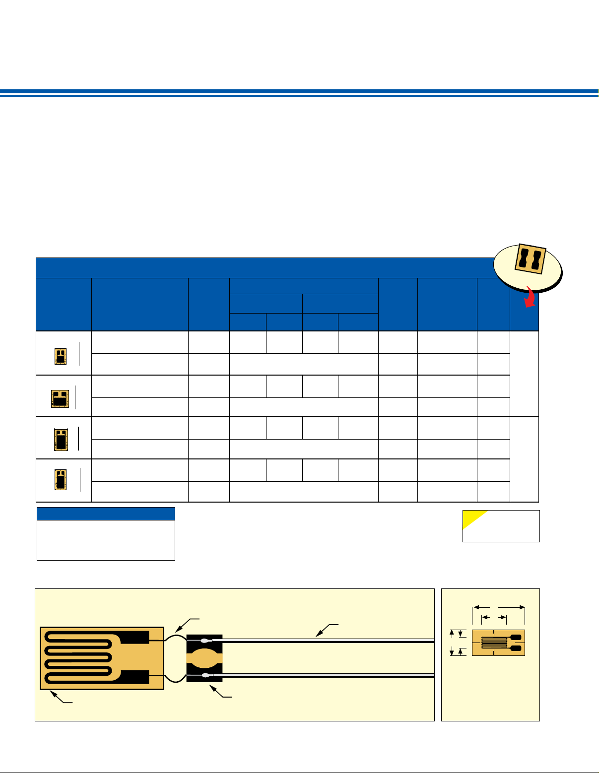
The linear pattern strain gages are used
to measure strain in a single direction.
The strain gage pattern is shown on
the left side of the table. Notice the
“arrow” which indicates the principal
stress direction.
The linear pattern strain gages are
available in a variety of styles and
sizes. OMEGA® offers miniature linear
patterns for strain measurement of a
To Order
GAGE
PATTERN
Shown
actual size
Leads not shown
5.5 mm
6 mm
7.5 mm
7.2 mm
DISCOUNT SCHEDULE
1 to 10 pkgs .................. Net
11 to 24 pkgs ..................5%
25 to 49 pkgs .................10%
50 and up and OEM ..Consult Factory
MODEL NO.
Pkg of 5
V
SGK-L1D-K350P-PC11-E
V
SGK-L1D-K350P-PC23-E
V
SGK-L1E-K350T-PC11-E
V
SGK-L1E-K350T-PC23-E
V
SGK-L3A-K350U-PC11-E
V
SGK-L3A-K350U-PC23-E
V
SGK-L3B-K350S-PC11-E
V
SGK-L3B-K350S-PC23-E
Maximum permitted bridge energizing voltage (Vrms).
*
Note: For strain gage accessories, visit us online.
Ordering Example: SGK-L3A-K350U-PC11-E, package of 5, linear pattern
strain gages with copper plated solder pads, nominal resistance 350 Ω.
U Good Linearity Over
Wide Temperature
Range -75 to 200°C
(-100 to 392°F)
stress concentration or high gradient
areas. The terminations are offered both
at one end of the grid, or with one at each
end of the grid. Wide or narrow linear
grid patterns are available.
To determine if the strain gages have
temperature characteristics matched
to steel or aluminum, see the column
labeled “COMP” short for compensation,
“ST” indicates steel, “AL” indicates
NOM.
RESISTANCE
(Ω)
350
350
350
350
350
350
350
350
DIMENSIONS mm (inch)
GRID CARRIER
A B C D
1.5
(0.059)
Miniature linear pattern, measurement
1.51
(0.059)
Miniature linear pattern, measurement
3.2
(0.126)
3.2
(0.126)
2.5
(0.098
of stress concentration 350 Ω
5.5
(0.22)4 (0.16)
4.5
(0.177)6 (0.24)6 (0.24)
of stress concentration 350 Ω
3.2
(0.126)
Small linear pattern, lead/pads
at one end of grid 350 Ω
2.5
(0.098)
Small linear pattern, lead/pads
at one end of grid 350 Ω
7.5
(0.3)
7.2
(0.28)4 (0.16)
†
4.6
(0.18)
U Good Fatigue Life
U Custom Gages Available
aluminum. See the column labeled
“BTP” for accessory bondable terminal
pad model numbers.
Dimensions are listed for pattern gage
grid length (A) and width (B), and the
matrix or carrier length (C) and width
(D). The patterns include alignment
triangles and letter codes indicating
creep code.
Visit us online
MAX V*
(Vrms)
6.5
9
8.5
12.5
10.5
14.5
9
13
TERMINATION
Solder Pads
Solder Pads
Solder Pads
Solder Pads
Solder Pads
Solder Pads
Solder Pads
Solder Pads
TEMP
COMP
TERM
PAD
ST
AL
BPT-1
ST
AL
ST
AL
BPT-2
ST
AL
NOTE
ST = Steel
AL = Aluminum
TYPICAL STRAIN GAGE INSTALLATION
Adhesive
Ribbon Leads from
Strain Gage or User Supplied
Fine Gage Wire (30 AWG)
Bondable Terminal Pads (BTP) for Stress Relief
and Junction for Different-Gage Wires
E-49
Instrumention Wire
20 to 28 AWG
† Dimensions Key:
C
A
BD
GRID
A: Active gage length
B: Active gage width
CARRIER
C: Matrix length
D: Matrix width
Page 2
karma strain gage
linear pattern strain gages
To Order
GAGE
PATTERN
Shown
actual size
Leads not shown
8.3 mm
8.5 mm
7 mm
11 mm
11 mm
11.3 mm
11.3 mm
DISCOUNT SCHEDULE
1 to 10 pkgs .................. Net
11 to 24 pkgs ..................5%
25 to 49 pkgs .................10%
50 and up and OEM ..Consult Factory
MODEL NO.
Pkg of 5
V
SGK-L3C-K350T-PC11-E
SGK-L3C-K350T-PC23-E
V
V
SGK-L3D-K350P-PC11-E
SGK-L3D-K350P-PC23-E
V
SGK-L3E-K350W-PC11-E
V
SGK-L3E-K350W-PC23-E
V
V
SGK-L6A-K350U-PC11-E
SGK-L6A-K350U-PC23-E
V
V
SGK-L6A-K1000U-PC11-E
SGK-L6A-K1000U-PC23-E
V
V
SGK-L6B-K350U-PC11-E
SGK-L6B-K350U-PC23-E
V
V
SGK-L6B-K1000U-PC11-E
SGK-L6B-K1000U-PC23-E
V
NOM.
RESIS-
GRID CARRIER
TANCE
DIMENSIONS mm (inch)
(Ω)
350
350
350
350
350
350
350
350
1000
1000
350
350
1000
1000
* Maximum permitted bridge energizing voltage (Vrms).
Note: For strain gage accessories, visit us online.
Ordering Example: SGK-L6B-K1000U-PC11-E, package of 5 linear pattern
strain gages with copper plated solder pads, temperature characteristics
matched to steel, nominal resistance 1000 Ω.
A B C D
3.2
(0.126)
lead/pad at each side of grid 350 Ω
2.8
(0.110)
lead/pad at each side of grid 350 Ω
3.2
(0.126)
6.3
(0.248)
6.3
(0.248)
resistance, reduced heat generation 1000 Ω
6.3
(0.248)
6.3
(0.248)
Linear pattern, large size, higher resistance,
3.1
(0.122)
Linear pattern, medium size,
2.1
(0.083)
Linear pattern, medium size,
8.3
(0.33)
8.5
(0.34)
1.5
(0.059)7 (0.28)3 (0.12)
Linear pattern, medium size,
grid width narrow 350 Ω
3.2
(0.126)
Linear pattern, large size 350 Ω
3.2
(0.126)
Linear pattern, large size, higher
4.4
(0.173)
Linear pattern, large size 350 Ω
4.4
(0.173)
reduced heat generation 1000 Ω
11
(0.43)
11
(0.43)
11.3
(0.44)6 (0.24)
11.3
(0.44)6 (0.24)
†
4.6
(0.18)
3.5
(0.14)
4.7
(0.18)
4.7
(0.18)
MAX V*
(Vrms)
10.5
14.5
8
12
7.5
10.5
15
20
25
35
17
24
28
28
TERMINATION
Solder Pads
Solder Pads
Solder Pads
Solder Pads
Solder Pads
Solder Pads
Solder Pads
Solder Pads
Solder Pads
Solder Pads
Solder Pads
Solder Pads
Solder Pads
Solder Pads
Visit us online
TEMP
COMP
TERM
PAD
ST
BPT-3
AL
ST
BPT-3
AL
ST
BPT-3
AL
ST
BPT-4
AL
ST
BPT-4
AL
ST
BPT-4
AL
ST
BPT-4
AL
NOTE
ST = Steel
AL = Aluminum
STRAIN GAGES
E
BONDABLE TERMINAL PADS
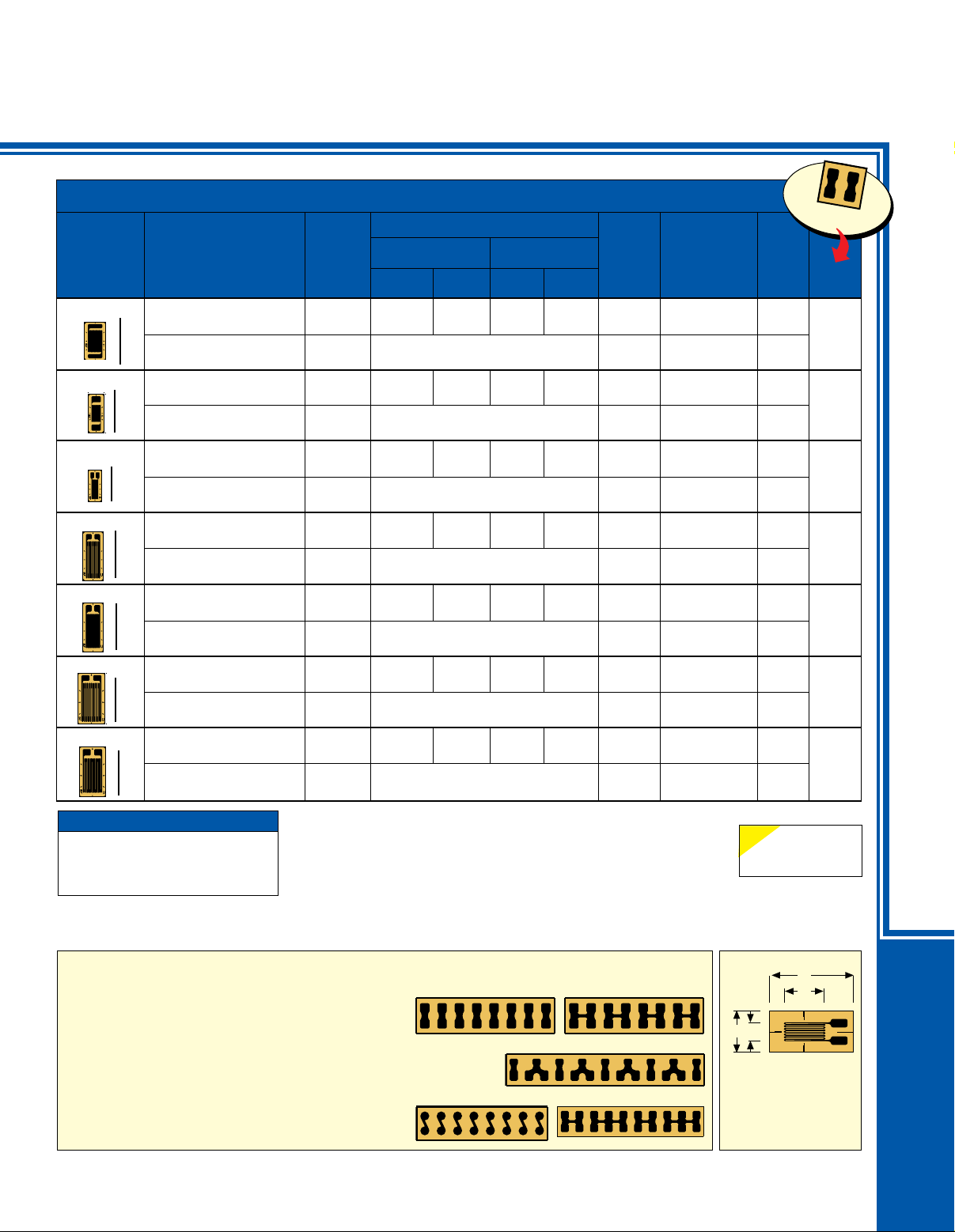
When installing strain gages with ribbon leads or
Solder Pads, use Bondable Terminal Pads (BTP)
between the strain gage and the wires to your
instrumentation.
The Bondable Terminal Pads provide a large easy
to use soldering area and provide strain relief between
the strain gage and the heavy instrument wires.
Using Bondable Terminal Pads is simple. Use the same
adhesive and bonding procedure on the Bondable
Terminal Pads as you use on the strain gage.
OMEGA offers BTPs in several sizes and wiring
configurations to fit most all strain gage applications.
visit us online for ordering information.
BTP
BTPB
Terminal pad patterns,
BTPD
BTPC
BTPE
E-50
† Dimensions Key:
C
A
BD
GRID
A: Active gage length
B: Active gage width
CARRIER
C: Matrix length
D: Matrix width
 Loading...