

Page 1
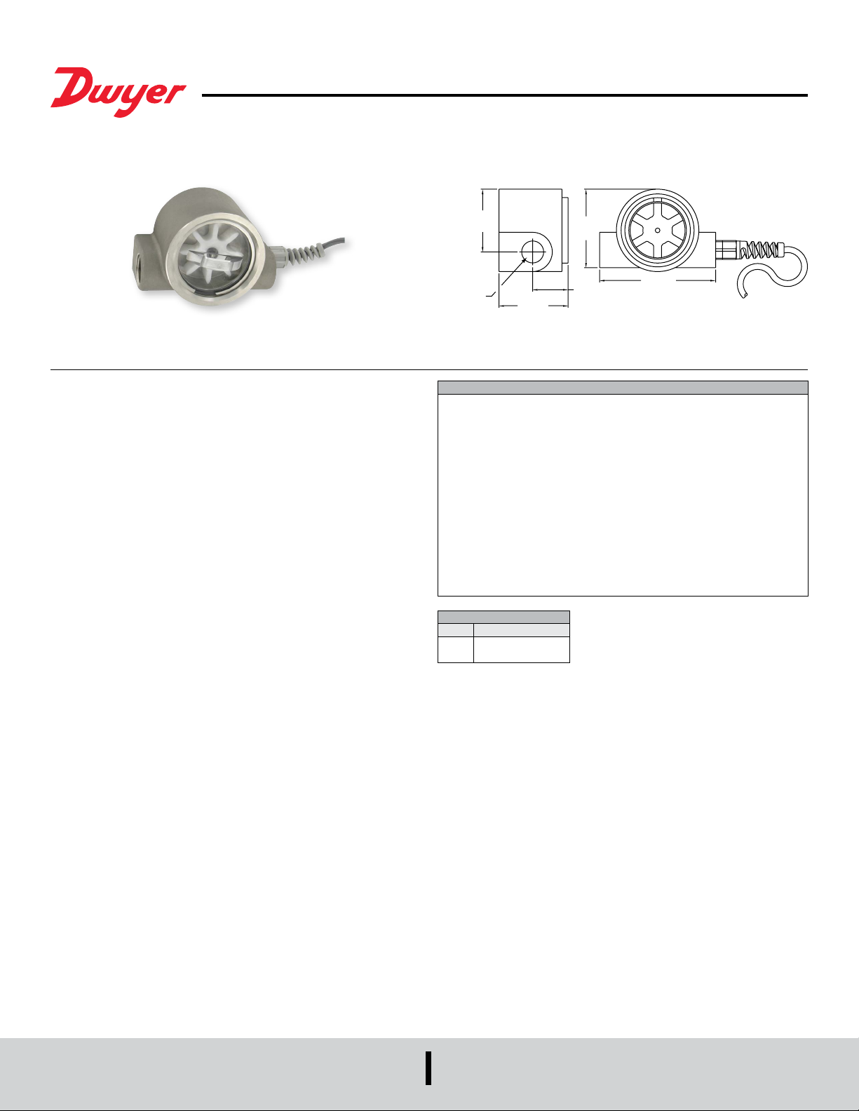
Series SF Sight Flow Transmitter
1/2˝ FEMALE NPT
[62.31]
®
Specications - Installation and Operating Instructions
Bulletin F-41-SF
Series SF Sight Flow Transmitter integrates tangential turbine technology with
hermetically sealed circuitry to provide accurate ow measurement and control in the
harshest environments. The 2-wire loop-powered design transmits a 4-20 mA signal
proportional to ow rate. Models can accurately measure ow in both directions and
can be mounted in any orientation. Series SF Transmitters are ideal for measuring ow
rates in cooling and lubrication circuits, HVAC systems, aggressive chemical metering,
and batching systems.
MECHANICAL INSTALLATION
The Series SF Sight Flow Transmitter has a 1/2˝ female NPT plumbing connections. It
is recommended to use a paste type pipe sealant on the threads. Teon tape sealant
can also be used as long as it is applied so the tape does not enter the ow stream
(pieces of tape can wrap around the turbine and impeded rotation).
The recommended mounting orientation would be any plane that will place the axis
of the turbine vertical or horizontal with respect to ground. The unit will operate
satisfactory with the axis at other angles, but side loading of the bearing surfaces will
lead to premature wear of the rotating parts.
For the best ow measurement results, place the inlet (references to “inlet” and “outlet”
refer to unidirectional systems) of the ow sensor at least 10 straight pipe diameters
downstream from any tting, valve, elbow, reducer, etc. that causes nonstable ow
conditions. Ideally, 5 straight pipe diameters should be placed at the outlet of the
sensor. If the sensor must be placed closer to a source of nonstable ow than the
recommended distances, some instability of the output signal may result. The average
signal will be accurate.
Place the sensor in such a position that the round access cover can be removed for
cleaning and turbine servicing. A union placed near the sensor is recommended to
allow easy removal.
ELECTRICAL INSTALLATION
The Series SF Sight Flow Transmitter is a 2-wire loop-powered device desined to
transmit a 4-20 mA signal proportional to ow rate. The noise-immune current
transmission from the sensor can be routed with low cost two conductor twisted-pair
cable. The current operates on 12-35 VDC and requires a source capable of supplying
at least 20 mA of current. The circuit has built-in polarity protection and over-current
limiting to protect both the sensor and what the sensor is connected to.
2
[50.80]
2-29/64
SPECIFICATIONS
Service: Compatible liquids.
Wetted Materials: 316 SS shaft and case, Iglide
-EPR units and acetal copolymer, (polycarbonate cover on Model SF11).
Flow Range: 0.5 to 15 GPM (2 to 60 LPM).
Accuracy: ±2% FS.
Repeatability: 0.5% FS.
Temperature Limits: 20 to 225°F (-7 to 107°C).
Pressure Limits: 500 psig (34 bar) Model SF10; 200 psig (14 bar) Model SF11.
Response Time: 2 s to 90% (step change in ow rate).
Supply Voltage: 12-35 VDC.
Output: 4-20 mA.
Loop Resistance: 1150 Ω max.
Process Connection: 1/2˝ female NPT.
Electrical Connection: Wire leads: 22 AWG x 9´ (2.7 m).
Max. Particle Size: 100 µm.
Agency Approvals: CE.
MODEL CHART
Model Cover Material
SF10
316 SS
SF11
Clear polycarbonate
To connect the sensor:
1. Connect the red wire from the sensor to the positive 12-35 VDC power supply
output.
2. Connect the black wire from the sensor to the positive side of the loop load (resistor,
chart recorder, data aquisition board, meter, etc.). This connection may be labeled
“4-20mAInput” on some devices.
3. If applicable, connect the negative side of the loop load to the negative side of the
power supply.
4. Apply power to the system.
5. If everything ois operating correctly, the green LED on the sensor will dimly
illuminate and 4 mA will be owing in the loop. If uid is owing through the sensor,
the current will be higher than 4 mA.
Troubleshooting
If the LED does not illuminate:
• Check wiring terminations for good connections.
• Check wiring polarity.
• Verify correct supply voltage.
• Insure the load impedance is within allowable limits.
• Apply the DC supply voltage directly across the sensor wires. If the LED does
illuminate, the load is either: too great of impedance or an open circuit. If the LED
does not illuminate, the sensor’s lead wires or circuit are defective.
2-5/8
[66.68]
1-9/64
[28.97]
3-45/64
[94.06]
®
bearings, Buna-N seal or EPR for
DWYER INSTRUMENTS, INC.
P.O. BOX 373 • MICHIGAN CITY, INDIANA 46360, U.S.A.
Phone: 219-879-8000
Fax: 219-872-9057
www.dwyer-inst.com
e-mail: [email protected]
Page 2

MAINTENANCE
The Series SF Flow Transmitter is designed to provide years of low maintenance
service in industrial environments. As with all mechanical rotating devices, the
bearing surfaces will wear with use. The life of the parts will depend on factors such
as cleanliness of uid, media, mounting orientation, temperature, uid velocity and
frequency of operation. The sensor was designed with simple eld replacement of the
rotating parts.
To inspect or replace the rotating components:
1. Relieve pressure in the piping system.
2. Remove the retainer ring that secures the turbine access cover.
3. Remove the access cover with pliers, taking care not to damage the o-ring seal.
4. Pull out turbine assembly and shaft.
5. Inspect the shaft for things that may have wrapped around it.
6. Inspect the turbine bearing surface for wear and elongation. Replace as necessary.
7. Clean any rust off of the magnets that may have accumulated.
8. Reassemble the unit by placing the turbine into the body cavity with the two magnet
pockets facing inward. Place the shaft into the turbine hole and guide it into the
retaining hole in the body cavity. Lubricate the o-ring with glycerine or other
lubricant and press it into the pocket of the body. Replace the retaining ring
securely before applying pressure to the system.
Circuit Recalibration:
1. Place a milliamp meter into the current loop.
2. Turn off the ow going through the sensor. Adjust the OFFSET control for a reading
of 4 mA on the milliamp meter.
3. Adjust the ow rate through the sensor to full ow rate. Adjust the SPAN control
for a reading of 20 mA on the milliamp meter. The zero and span adjustment are
not interactive and should require additional adjustments.
DWYER INSTRUMENTS, INC.
P.O. BOX 373 • MICHIGAN CITY, INDIANA 46360, U.S.A.
Iglide® is a registered trademark of Igus GMBH
Printed in U.S.A. 9/21 FR# 443038-00 Rev. 2©Copyright 2021 Dwyer Instruments, Inc.
Phone: 219-879-8000
Fax: 219-872-9057
www.dwyer-inst.com
e-mail: [email protected]
 Loading...