

Page 1
Quick Start Guide
O2 Measurement / Amperometric ZrO2
Quick Start Guide GSB electronics + sensor
The quick start guide is intended for factory calibrated systems, i.e. systems delivered with pre-installed sensor
Mounng, housing and cable pairing
The GSB is supplied as a PCB. Housing and mounng should be provided, to prevent ESD or short circuit issues.
For systems with cables, it is important to understand that the calibraon data of each sensor is stored on the GSB,
so it is not possible to connect a dierent sensor without recalibraon. The orientaon of the cable connecon is
only veried via an electronic polarity check. The GSB will stay in contact check mode unl a correctly connected
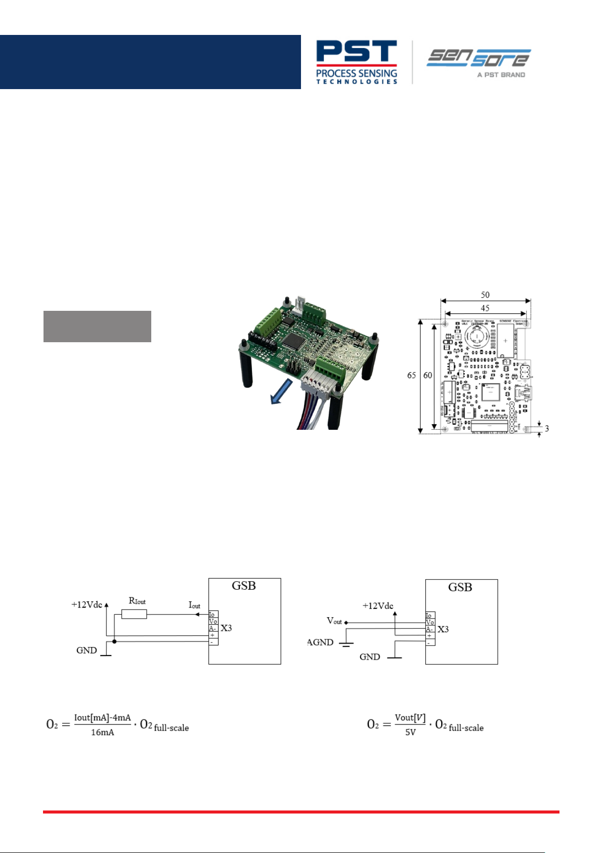
sensor is detected. See Figure 1 for correct cable connector orientaon. In case of an onboard mounted sensor
(TO8 or TO39 housing), no cable sensor must be connected.
Type Label Informaon
EGa0202std-D0010A300
C809912- 0 03
S: 9110225H03 05/25
1. Line: System Type
e.g. EGa0202std-D0010A300
2. Line: Batch + Ser. No.
e.g. C809912 - 003
3. Line le: Sensor engraving
e.g. 9110225H 03
ID of the factory-calibrated sensor.
System will only correctly operate
when this sensor is connected!
3. Line right: calibraon date
e.g. 05/25 => week: 05 year: 25
Figure 1 GSB with c abled sensor, orientaon!
(System delivered without mounng accessories)
GSB dimensions in mm
Electrical interface and O2 signal output
The recommendaon is to use a dedicated power supply with 12Vdc/500mA, which is also applied during
calibraon and oers the opmal performance in regards of accuracy and thermal load of the board. The power
supply must ensure protecon against hazardous voltages, e.g. SELV, NEC Class 2
Analogue current output 4-20mA (nominal)
Figure 2 connecon circuit
Analogue voltage output 0-5V (nominal)
The calculaon of the O2 concetraon is based on the analogue output and the O2 full-scale value
Overrange capability of analogue outputs and the O2 measurement:
The analogue current output displays over-ranges up to 125% full scale, i.e. 24mA
The analogue voltage output displays over-ranges up to 120% full scale, i.e. 6V
Excepon is the 96% O2 sensor range, there the outputs are limited to 100% O2, respecvely 20mA or 5V.
ProcessSensing.com
250217 ega0202std quickstart guide
Page 2
Selecon guide for calibrated systems
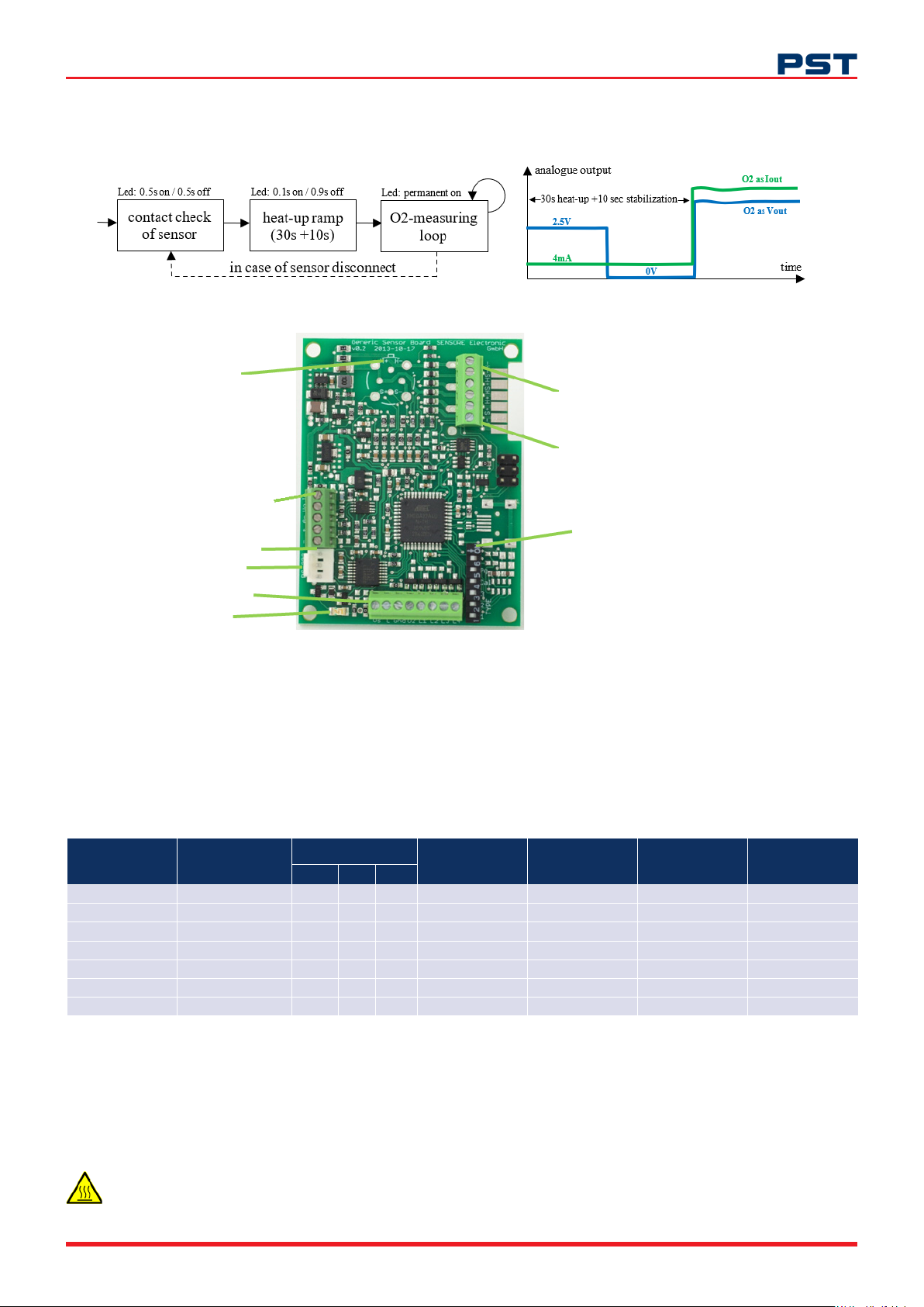
Behaviour aer power-up and indicaon via LED, 4-20mA / 0-5V Output
Figure 3 Power-up states and indicaon via LED and analogue output
Sensor onboard:
Orientaon n ib for TO8
TO8 must b e sold ered wi th 2-3mm air
gap bet ween PCB and base plate
TO39 must be mounted via socket,
which will be preinst alled.
X3 (Power/analogue)
1 … [Io] 4-20m A output
2 … [Uo] 0-5 V output
3 … [A-] analo gue GND
4 … [+] +12Vdc supply
5 … [-] GND suppl y
X4 (RS232)
X1 (oponal Outputs)
LED
Figure 4 GSB main interfaces and DIP-switches
X2a/b Sensor o board:
to conne ct sen sors with cab le, via PCB edge plug (Rast2 .5
see Fig ure 1), or v ia screw t ermin al
6… [H-] heater- white c able
5… [HS-] heater- (sense line) white cabl e
4… [HS+] heat er+ (sense line) violet cab le
3… [H+] heat er+ violet c able
2… [S+] sensor cell+ re d cabl e
1… [S-] sensor cell - black c able
DIP Switches
Preset upon de liver y, do not cha nge the seng
6 … not in use, should alway s be o
5 … progr am mode, should alway s be o
4 … (re)ca libra on switch, should a lways be o
opera ng it, will overwrite the fa ctor y calibrao n!
1-3 GSB para meter p reset s, see Table 1
GSB Parameter Presets / DIP Switch
For factory calibrated systems there is no need to interfere with the DIP-switch seng. The O2 range is dened by
the sensor type, the DIP-switches do not change that, they will just select the matching FW-parameters.
Warning: operang the calibraon DIP-switch will void/overwrite the factory calibraon.
O2 range
(min / max)
GSB
preset
10-100 0ppm 1 OFF ON ON 1000 vol.-ppm 1000 vol.-ppm +/- 20ppm 0.70 Vdc
0.01-1vol.% 2 ON OFF ON 1 vol.-% 1 vol.% +/- 0 .01vo l.% 0.75 Vdc
0. 01-2 vol .% 3 OFF OFF ON 2 vol.-% 2 vol.% +/- 0 . 2vo l .% 0.75 Vdc
0.05-5vol.% 4 ON ON OFF 5 vol .-% 5 vol.% +/- 0.5vol . % 0.8 0 Vd c
0.1-25vo l.% 5 OFF ON OFF 25 vo l.-% 20.9 vol.% +/- 0. 5vo l .% 0.85 Vdc
50-96vol.% 6 ON OFF OFF 10 0 vol.-% 20.9 vol.% +/- 1v ol.% 1.60 Vdc
1-96vo l.% 7 OFF OFF OFF 100 vol.-% 20.9 vol.% +/- 1v o l.% 1.00 Vdc
Table 1 GSB pa rame ter pre sets as d ene by D IP swit ch sen g
DIP switch bit
1 2 3
GSB
full scale (output)
O2-calibration
concentration
Typical Accuracy Sensor Voltage
Thermal consideraon
The GSB, in general, is specied to be operated between 0 and 50°C (ambient). For sensors directly mounted on the
GSB, the thermal load on the board is higher, ensure reasonable heat exchange to avoid heat buildup at the board.
Warning: during operaon sensor casings might reach temperatures, which must be rated as
"hot surface”. Consider the placing of a warning (scker) if the sensor is accessible by the end user.
ProcessSensing.com
250217 ega0202std quickstart guide
 Loading...