

Page 1
ACE
ALL DIMENSIONS IN INCHES (MILLIMETERS)
[98.5]
SERIES SC1
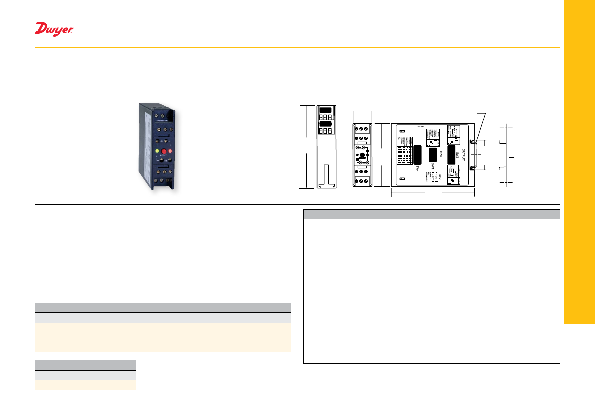
PROCESS/TEMPERATURE ALARM SWITCH MODULE
Two Form C (SPDT) Switches, Small Size, Mounts Easily on 35 mm DIN Rail
PROCESS CONTROL
The Series SC1 Process/Temperature Alarm Switch Module is an on-off or limit
switch with selectable process signal. Each unit has two form C (SPDT relays which
can operate independently, or be logically connected to operate as a DPDT output.
BENEFITS/FEATURES
• Accepts current, voltage, thermocouple, or RTD inputs
• Mounts on standard 35 mm DIN rail
• Two color LED indicator to indicate the status of each output relay
• Programmable input type, scale range, output action, and output type
APPLICATIONS
• Stand alone CO monitoring in parking garage
• Industrial processing equipment
MODEL CHART
Model Description Power Supply
SC1090
SC1290
SCL1090
SCL1290
ACCESSORIES
Model Description
A-360 Aluminum DIN rail 1 m
4-20 mA, 10-50 mA, 0-20 mA, 0-10 V, -10-10 mV
Thermocouple type J, K, R, S, T, E RTD Pt1000 4-20
mA, 10-50 mA, 0-20 mA, 0-10 V, -10 to 10 mV
Thermocouple type J, K, R, S, T, E
85-265 VDC/VAC
85-265 VDC/VAC
12-24 VDC/VAC
12-24 VDC/VAC
0.886˝
[22.5]
3.88˝
[98.5]
SPECIFICATIONS
Input: See table.
Power Supply: SC models: 85-265 VDC/VAC, 50 to 400 Hz; SCL models: 12-24
VDC/VAC, 50 to 400 Hz.
Isolation: 1500V rms between outputs, input, and power.
Set Points: Adjustable 0 to 100% of span.
Deadband: Adjustable 0.25% to 100% of span.
Drift: ±0.02%/°C typical ±0.05%/°C maximum.
Ambient Temperature Range: Operating: 32 to 131°F (0 to 55°C); Storage: -40 to
176°F (-40 to 80°C).
Excitation Current: Cu10 Ω = 5 mA; Plt 100 Ω, Ni 100 Ω, Ni 120 Ω = 500 µA; Plt
500 Ω, NiFe 1000 Ω = 100 µA; Plt 1000 Ω = 50 µA.
Lead Compensation Error: ≈ 0.02%/Ω.
Open Lead Protection: Upscale only.
Input Impedance: SC1090: Voltage input = 1 MΩ, current input = 10 Ω; SC1290: 3
MΩ.
Sensor Burnout Protection: Selectable.
Relay Output: Form C, SPDT, one per set point, 5A @ 250 VAC, resistive.
Latch Circuit Reset: Automatic at power up. Manual with reset switch on front of
module.
Indicators: One dual color LED per set point. Red = relay on, green = relay off.
Wiring Terminals: Screw driven compression type.
2.95˝
[75]
DIN EN 50022-35
[NOT SUPPLIED]
3.88˝
1.40˝
[35.3]
ADAPTOR
BRACKET
FOR SURF
MOUNTING
[OPTIONAL]
 Loading...