

Page 1

SBG54803A, Solid-State Relays
For Intrinsic Safety Use
Instruction Sheet M1775/0515
DESCRIPTION
The OMEGA® SBG54803A Dual Channel Zener Barrier is a solid-state,
energy-limiting device for transmitting direct current signals of less than 20V and
less than 100mA in an intrinsically safe manner. The unit is designed to be used in
conjunction with indicating equipment in hazardous areas defined as Class I,
Division 1, and inclusive of Groups A through D. This zener barrier is used
where circuit common is earth-ground referenced.
THE AMBIENT TEMPERATURE OPERATING RANGE OF
THIS DEVICE IS 0° TO 60° C. (+32° TO +140° F).
UNPACKING
Remove the Packing List and verify that you have received all equipment. If you have any
questions about the shipment, please call the OMEGA Customer Service Department
at 1-800-622-2378 or (203) 359-1660. When you receive the shipment, inspect the
container and equipment for any signs of damage. Note any evidence of rough handling in
transit. Immediately report any damage to the shipping agent.
NOTE
The carrier will not honor any claims unless all shipping material is saved for their examination.
After examining and removing contents, save packaging material and carton in the event
reshipment is necessary.
Important: Read carefully and completely before
installing or connecting the solid-state relays.
CONSIDERATIONS FOR INSTALLATION AND USE
Only one sensor per channel may be connected to a barrier
The barrier and receiving station must be located in a non-hazardous location.
The mounting bracket on the barrier must be connected to an earth ground from both
mounting points and two lines for redundancy. The grounding should be adequate for
conduction of line generated fault currents. The resistance of either line to earth
ground should be maintained at less than one ohm.
To serve multiple tank installations, additional barriers may be placed in an enclosure
using a common earth ground
wiring should be segregated from non-intrinsically safe wiring by independent raceways,
wiring trays or other adequate means to insure the integrity of the installation.
Additionally, when internal terminations are used, intrinsically safe wiring and
non-intrinsically safe wiring should not be adjacent or arranged in such a way as to
create the potential to miswire or bypass the barrier during servicing or testing.
(See typical installation depicted in Figure 2.)
Common, commercially available signal wire may be
used for field wiring and distances of up to 1000 ft. are
acceptable using twisted wire. Characteristics of the
signal line should not be modified by addition of
capacitive or inductive components.
Each sensor must have its own ground return wire to pin 5.
The governing parameters for various groups are as follows:
Hydrogen &
Acetylene
Ethylene C 1.2 µF 5.0mH
(See Figure 2)
Group Capicitance* Inductance*
A & B 0.4 µF 0.9 mH
. In this enclosure, the intrinsically safe
(See Figure 1)
Product must be maintained
and installed in strict
accordance with the National
Electrical Code. Failure to
observe this warning could
result in serious injuries or
damages.
.
WARNING
Methane D 3.2 µF 10.0mH
Note: *Values are for any one loop in the hazardous area.
(i.e., Terminals 7 to 5 or 8 to 5)
Field Testing of Barrier
A. Never conduct tests while circuit is active. The use of
instruments between input and output terminals will bypass the barrier.
Page 2
B. All testing is to be done with circuit inactive using the following instruments:
1. Ohmmeter with resolution down to less than 1 ohm.
2. D. C. power supply with an output of 0 to +25 VDC.
3. D. C. voltmeter.
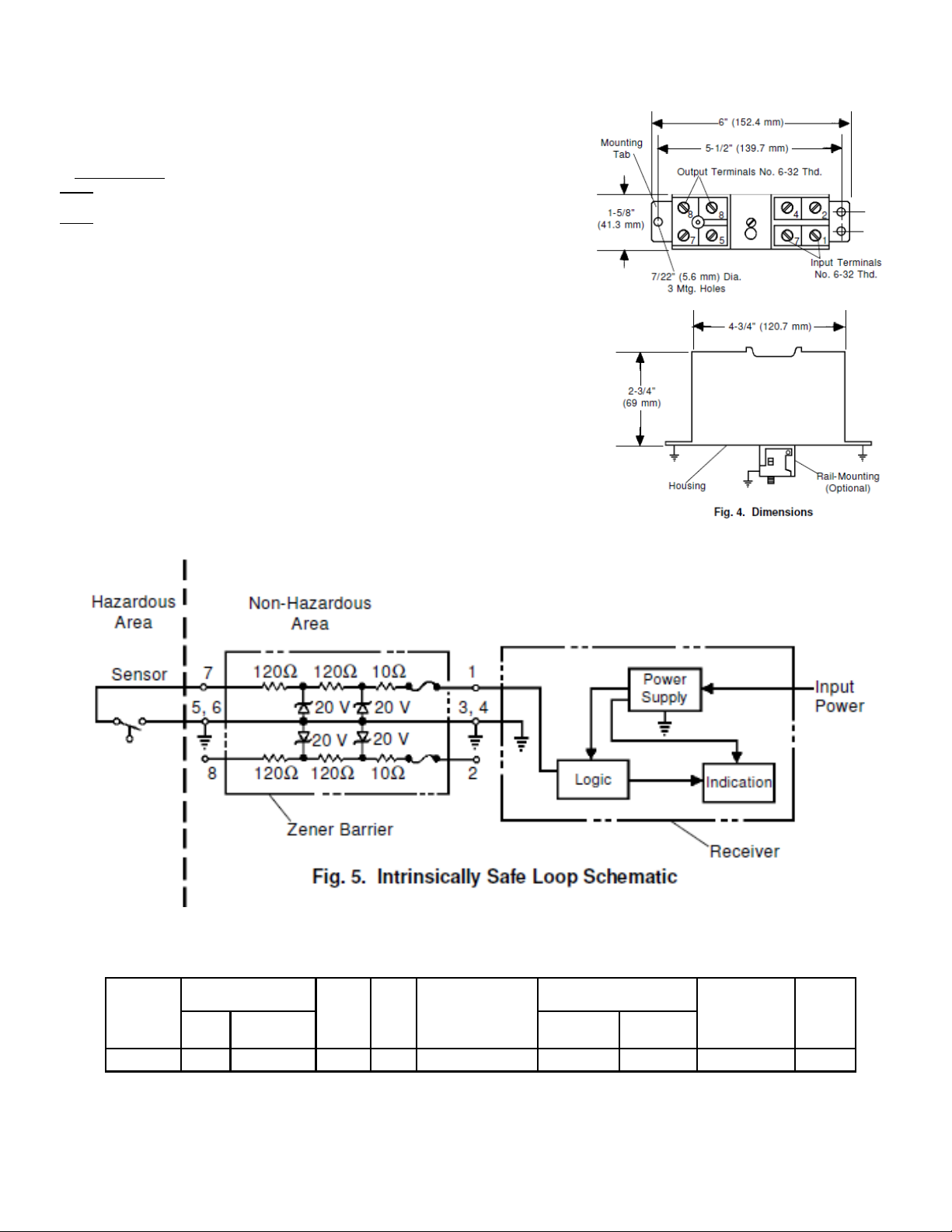
C. Test performance (See Fig. 5)
Step 1:
Disconnect all leads to unit under test except to the earth grounding mounting tabs.
Step 2:
a. Measure the resistance between terminals 1 & 7 and then 2 & 8. This resistance should be
250 ohms ±5% (± instrument tolerance).
b. Measure the resistance between terminals 5 & 3 and then terminal 5 and the mounting tab.
Both readings should be below one ohm.
c. Apply 24 volts to terminals 7(+) and 5 (common). Then read the voltage between the termi-
nals 1 (+) and 3 (common)*. This voltage must be between 18.5 and 21.5 volts. In the same
fashion, conduct this same test with the voltage connected across 8 (+) and 5 (common) and
measure the output across 2 (+) and 3 (common).
d. Connect an ohmmeter between the mounting tab (not the mounting screw) and the earth
ground reference. The reading must be less than one ohm. The barrier must pass all
parts of this test or it is unacceptable.
* The fuses located in the circuits 7-1 and 8-2 are
rated at 100mA. Therefore, care should be exercised
in testing this device so that no accidental current greater than
100mA enters or leaves terminal 1 or 2.
Note: Every effort should be made to keep these barriers clean and free of contaminating atmospheres.
A periodic check should be made to verify that they are in good condition, physically and electrically.
Table 1. Specifications
DC Input to
Model
Number
SBG54803A 20 100 Positive 270 Groups A, B, C, D 0.4 0.9 0° to +60°C 495g
Barrier, Max.
Voltage
Fuse Rating
Current, mA
Signal
Polarity
Series
Resist.
Applications
Groups
Class i & II, Div 1, 2
Reactive Limits
Capacitance
µF
Inductance
mH
Ambient
Oper.
Temp.
Weight
Page 3
P/N 158351 rev A
 Loading...