

Page 1
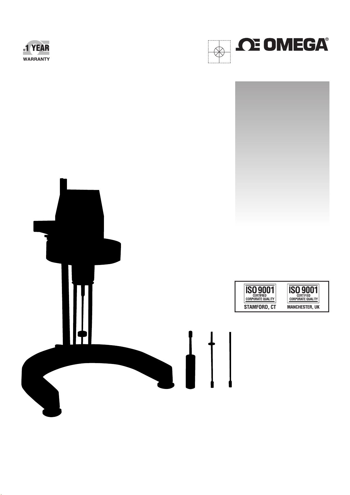
User’s Guide
Shop online at
omega.com
e-mail: [email protected]
®
For latest product manuals:
omegamanual.info
MADE IN CHINA
RVB-1
Rotational Viscometer
Page 2

OMEGAnet®Online Service Internet e-mail
omega.com [email protected]
Servicing North America:
U.S.A.: Omega Engineering, Inc., One Omega Drive, P.O. Box 4047
ISO 9001 Certified Stamford, CT 06907-0047 USA
Canada: 976 Bergar
Laval (Quebec), H7L 5A1 Canada
Toll-Free: 1-800-826-6342 TEL: (514) 856-6928
FAX: (514) 856-6886 e-mail: [email protected]
For immediate technical or application assistance:
U.S.A. and Canada: Sales Service: 1-800-826-6342/1-800-TC-OMEGA
Customer Service: 1-800-622-2378/1-800-622-BEST
Engineering Service: 1-800-872-9436/1-800-USA-WHEN
®
®
®
Servicing Asia:
China: 1698 Yi Shan Road, Unit 102,
Min Hang District, Shanghai, China
Hotline: 800 819 0559/400 619 0559 e-mail: [email protected]
Servicing Europe:
Benelux: Toll-Free: 0800 099 3344 TEL: +31 20 347 21 21
FAX: +31 20 643 46 43 e-mail: [email protected]
Czech Republic: Frystatska 184
733 01 Karviná, Czech Republic
Toll-Free: 0800-1-66342 TEL: +420-59-6311899
FAX: +420-59-6311114 e-mail: [email protected]
France: Toll-Free: 0805 541038 TEL: 01 57 32 48 17
FAX: 01 57 32 48 18 e-mail: [email protected]
Germany/ Austria: Daimlerstrasse 26
D-75392 Deckenpfronn, Germany
Toll-Free: 0800 8266342 TEL: +49 (0) 7056 9398-0
FAX: +49 (0) 7056 9398-29 e-mail: [email protected]
United Kingdom: OMEGA Engineering Ltd.
ISO 9001 Certified One Omega Drive, River Bend Technology Centre, Northbank
Irlam, Manchester M44 5BD United Kingdom
Toll-Free: 0800-488-488 TEL: +44 (0) 161 777-6611
FAX: +44 (0) 161 777-6622 e-mail: [email protected]
It is the policy of OMEGA Engineering, Inc. to comply with all worldwide safety and EMC/EMI
regulations that apply. OMEGA is constantly pursuing certification of its products to the European New
Approach Directives. OMEGA will add the CE mark to every appropriate device upon certification.
The information contained in this document is believed to be correct, but OMEGA accepts no liability for any
errors it contains, and reserves the right to alter specifications without notice.
WARNING: These products are not designed for use in, and should not be used for, human applications.
Page 3

RVB-1
Rotational Viscometer
Operation Manual
Page 4

1
Contents
I. Summary……………………………………………………...……….2
II. Technical specifications and parameters………………………….2
III. Instrument structure and installation…………………………...……..2
IV. Operation methods……………………………………………………6
V. Notes………………………………………………………………8
VI. Package List ........................................................................................ 11
Page 5

2
I. Summary
The RVB-1 is used to determine viscosities of greases, paints, plastics, foods,
pharmaceuticals, adhesives, and various fluids.
II. Technical specifications and parameters
1. Measurement range: 10 cps100000 cps
2. Measurement error: ±5% (F·S)
3. Spindles: No.1, 2, 3 and 4 spindles
4. Rotation speed: 6 RPM, 12 RPM, 30 RPM, and 60 RPM
5. Power supply: AC 120V±10%, 50Hz±10%
6. Size: 300 × 300 × 450 mm (11.81 x 11.81 x 17.71 in)
7. Net weight: 1.5 kg (3.3 lb)(not including the holder)
III. Instrument structure and installation
(I) Instrument structure
1. Principle of the structure
The structure of the instrument is shown as Figure 1.
(1) Motor (2) Dial (3) Indication needle (4) Hair spring
(5) Liquid to be determined (6) Spindle
Figure 1
Page 6

3
(1) Rubber band (2) Speed knob (3) Water level meter
(4) Indication needle (5) Needle control rod (6) Power switch
(7) Coefficient table (8) Dial
Figure 2
(1) The motor rotates at a stable speed, connecting the dial and rotating the spindle
through the hair spring and the rotation shaft. If the spindle is not affected by the liquid
resistance, the hair spring, the indication needle and the dial will rotate at the same speed.
The reading on the dial is 0. If the spindle is affected by liquid resistance, the hair spring
will produce a torque moment to balance with the viscidity resistance producing a reading
on the dial (The torque angle of hair spring).
Multiply the reading by a specific coefficient to get the viscosity of liquid (cps).
(2) The RVB-1 uses a gear system and clutch to change rotation speed using the
speed knob. The instrument has four grades of speed enabling the user to select a suitable
speed per test requirements.
(3) Four different spindles are supplied from No. 1 to 4. The choice of spindle is
based on the estimated viscosity of the liquid to be determined.
(4) In order to accurately read the dial, the RVB-1 is equipped with a fixing device
for indicator needle (Needle control rod). When the rotation speed is high (30 or 60 RPM),
and it is difficult to read the dial, press down the needle control rod to hold the needle for
ease of reading.
(5) The protection shield is designed for measurement stability and spindle
protection. When the protection shield is used during measurement, a more stable
Page 7

4
measurement results.
(6) The RVB-1 is equipped with a holder that can be adjusted up or down. The
instrument should be fixed during measurement.
2. The complete structure
(1) The structure of the instrument head is shown as Figure 2.
(2) The complete structure of the instrument is shown as Figure 3.
(1) Power supply wire (2) Water level meter (3) Instrument head (4) Dial
(5) Protection cap (Please remove it before operation) (6) Pedestal (7) Spindle
(8) Spindle protection shield (9) Inside-hexagonal spanner
(10) Water Level adjustment bolt
Figure 3
5 4 3 2 1 6 7 8 9
10
Page 8

5
(3) Available Spindles:
(1) No. 3 spindle (2) No. 2 spindle (3) No. 1 spindle
(4) No. 4 spindle (In the protection shelve)
Figure 4
(II) Installation
1. Remove pedestal and vertical shaft from the package.
2. Install the vertical shaft on the pedestal through the hole at the back of the pedestal.
The notched side of the vertical shaft should face to the back of the pedestal. Fasten the
hexagonal nut to avoid rotation of the vertical shaft.
3. Install the clamp on the vertical shaft and rotate the clamp knob to check
flexibility and self-lock function. If the clamp is too tight or too loose, adjust the locknut
at the back of the clamp using a screwdriver until it can move up and down. The clamps
should be a little tight to avoid the instrument head falling down after installation.
4. Open the storage case and remove the viscometer. Install the viscometer on the
clamp. Fasten the fixing bolt and remove the rubber band from the needle control rod.
Unscrew the bolt on the protection cap at the bottom of the instrument head and
take off the protection cap.
5. Rotate the level adjustment bolt to level the instrument.
6. Connect the instrument to the power supply.
(1)
(2)
(3)
(4)
Page 9

6
IV. Operation methods
1. Prepare the liquid to be measured in a beaker or cylinder not less than 70 mm in
diameter. Please control the liquid temperature accurately.
2. Install the protection shield on the instrument (Rotate it right to assemble and
rotate it left to disassemble).
3. Screw on the selected spindle on the connection bolt (Rotate it left to assemble
and rotate it right to disassemble). Rotate the clamp knob to lower the instrument into the
liquid to be determined slowly until the liquid surface sign on the spindle is level with the
liquid surface. Level the instrument, turn on the motor switch, and rotate the speed knob
to select a suitable speed. The spindle will begin rotating in the liquid. When the
indication needle is stable after the spindle rotates a number of times, the measurement
can be obtained from the reading on the dial. In general, it takes about 20 to 30 seconds,
or longer. Press down the needle control rod to fix the reading, and then turn off the motor
when the needle appears in the reading window. (Note: 1. Please be gentle during
operation; 2. If the rotation speed is slow, you can read the reading directly without
the help of the needle control rod).
4. If the reading is too high or too low, you can select a different spindle or a
different speed to let the reading stay in the range of 30 to 90.
5. Full scale, coefficient, spindle and speed selection:
(1) Please estimate the viscosity range of the liquid to be determined, and then select
a suitable spindle and speed from the full scale table.
For example, the viscosity of liquid to be determined is about 3000 cps, then you can
select:
No.2 spindle with 6 RPM or No.3 spindle with 30 RPM;
(2) If the viscosity range of the liquid to be determined is unknown, please proceed
based on the highest viscosity. Then select a spindle from small to large volume and a
speed from slow to quick. In general, select the smallest volume spindle and the slowest
speed for high viscosity liquids and select the largest volume spindle and the quickest
speed for low viscosity liquids.
(3) Coefficient: The dynamic viscosity is calculated by multiplying the reading on
Page 10

7
the dial by the specific coefficient on the coefficient table.
η=K·α
Where:
η = Dynamic viscosity;
K= Coefficient;
α =Reading on the dial (Deflection angle)
(4) Frequency error modification: when the power frequency is not same with the
stipulated frequency, please modify it using the following equation.
Real viscosity= indication viscosity × (Rated frequency / Real frequency)
(5) Viscosity unit conversion:
Dynamic viscosity unit conversion
1 cP=1 mPa·s
100 cp= 1 P
1000 mPa·s= 1 Pa·s
Dynamic viscosity and kinematic viscosity conversion
η=ν·ρ
Where:
η= Dynamic viscosity (mPa·s);
ν= Kinematic viscosity (mm2/s);
ρ= Density at the temperature when determining the kinematic viscosity (g/cm3);
Page 11

8
(6) Full scale table
RPM
Full scale
cps
Spindle
60
30
12
6
1
100
200
500
1000
2
500
1000
2500
5000
3
2000
4000
10000
20000
4
10000
20000
50000
100000
(7) Coefficient table
RPM
Coefficient
K
Spindle
60
30
12
6
1
1 2 5
10
2
5
10
25
50
3
20
40
100
200
4
100
200
500
1000
V. Notes:
1. Operate the instrument under the ambient temperature.
2. Operate the instrument with the stipulated frequency and voltage tolerance range;
or, it will affect test accuracy.
3. Use the holder during operation. Keep the instrument stable and level during
operation.
4. Use caution when assembling or disassembling the spindle. Do not apply too great
a force and do not move the spindle in the transverse direction to avoid bending the
Page 12

9
spindle.
5. Do not set the instrument side down or upside down.
6. Change speed only when the motor is running.
7. Keep the connection bolt, connection section and screw thread of spindles clean,
or it will affect connection and rotation stability of spindle.
8. Hold the bottom of the instrument head by hand when adjusting the position of the
instrument head to avoid instrument head falling.
9. Clean the spindle after each test. Remove RVB-1 from the instrument and clean it.
Do not clean spindle when it is still on the instrument. Store in a proper place after
cleaning.
10. Do not disassemble the instrument unnecessarily. Do not add any lubricant oils
to the instrument.
11. Fix the needle control rod and fasten the connection bolt using the protection cap
when moving or transporting the instrument.
12. Suspension, emulsion, high polymer and most other liquids are Non-Newton
liquids. Their apparent viscosities will change together with change of the shear speed and
time, so it is normal when the test results are different using different spindles, speeds and
time. The viscosities of Non-Newton liquids measured using the instrument are only for
reference. (In general, you should make determination for Non-Newton liquids using the
stipulated spindle, speed and time or make comparative measurement at fixed
measurement condition and environment to verify their viscosities).
13. To get more accurate results, pay close attention to the following points:
(1) Control the liquid temperature accurately;
Note: If necessary, please purchase a circulation constant temperature bath and
a double layers sample cup.
(2) Immerse the spindle in the liquid to be measured for a sufficient time to establish
a constant temperature, where both spindle and liquid to be measured are at the same
temperature.
(3) Ensure that the liquid is uniform.
(4) Let the spindle stay in the center of the sample container during determination.
Page 13

10
(5) Ensure no bubbles adhere to the bottom of the spindle when immersing the
spindle into the liquid to be measured.
(6) Select suitable spindle and speed to make sure the reading on the dial is higher.
(7) Use the protection shield during determination.
(8) Keep the spindle clean.
(9) Modify the power frequency affect when it changes.
(10) Make determination as per the operation methods.
14. If the needle does not move during determination, please check the needle
control rod to ensure the rubber band is removed. If it is not removed, please remove it
and press the needle gently for several times. If the needle can move up or down, the
needle is in normal.
15. The hair spring has been preset and the needle will point to zero when the RVB-1
is turned on. If it does not point to zero, check the instrument to make sure it is level.
Caution: The zero position of the instrument is not at the position “1”. It is at
the two black triangles position.
Note: The instrument is composed of gear box, hair spring, and bearing. It is a
precision instrument, and should be handled gently during installation and
operation. Do not disassemble the instrument or change any parts.
Page 14

11
VI. Package List
1. Full set
No.
Name
Unit
Quantity
1
Main unit
Set
1
2
N0.1 to 4 spindles
Piece
1 for each
3
Protection cap (Remove before turning on the instrument)
Piece
1
4
Vertical shaft
Piece
1
5
Pedestal (with two level adjustment bolts)
Pair
1
2. Optional part
(1) RVB-T-TB Circulation Constant Temperature Bath 1 set
(2) RVB-1-DLC Double layers sample cup
3. Technical documents
(1) Operation Manual 1 piece
Page 15

WARRANTY/DISCLAIMER
OMEGA ENGINEERING, INC. warrants this unit to be free of defects in materials and workmanship for a
period of 13 months from date of purchase. OMEGA’s WARRANTY adds an additional one (1) month
grace period to the normal one (1) year product warranty to cover handling and shipping time. This
ensures that OMEGA’s customers receive maximum coverage on each product.
If the unit malfunctions, it must be returned to the factory for evaluation. OMEGA’s Customer Service
Department will issue an Authorized Return (AR) number immediately upon phone or written request.
Upon examination by OMEGA, if the unit is found to be defective, it will be repaired or replaced at no
charge. OMEGA’s WARRANTY does not apply to defects resulting from any action of the purchaser,
including but not limited to mishandling, improper interfacing, operation outside of design limits,
improper repair, or unauthorized modification. This WARRANTY is VOID if the unit shows evidence of
having been tampered with or shows evidence of having been damaged as a result of excessive corrosion;
or current, heat, moisture or vibration; improper specification; misapplication; misuse or other operating
conditions outside of OMEGA’s control. Components in which wear is not warranted, include but are not
limited to contact points, fuses, and triacs.
OMEGA is pleased to offer suggestions on the use of its various products. However,
OMEGA neither assumes responsibility for any omissions or errors nor assumes liability for any
damages that result from the use of its products in accordance with information provided by
OMEGA, either verbal or written. OMEGA warrants only that the parts manufactured by it will be
as specifi ed and free of defects . OMEGA MAKES N O OTHER WARR ANTIES O R
REPRESENTATIONS OF ANY KIND WHATSOEVER, EXPRESS OR IMPLIED, EXCEPT THAT OF TITLE,
AND ALL IMPLIED WARRANTIES INCLUDING ANY WARRANTY OF MERCHANTABILITY AND
FI TNESS FOR A PARTICULAR PURPO SE ARE HEREBY DI SCLAIMED. LIMI TATION OF
LIABILITY: The remedies of purchaser set forth herein are exclusive, and the total liability of
OMEGA with respect to this order, whether based on contract, warranty, negligence,
indemnification, strict liability or otherwise, shall not exceed the purchase price of the
co mponent upon w hich li ability is based. In no event shall OMEGA be lia ble for
consequential, incidental or special damages.
CONDITIONS: Equipment sold by OMEGA is not intended to be used, nor shall it be used: (1) as a “Basic
Component” under 10 CFR 21 (NRC), used in or with any nuclear installation or activity; or (2) in medical
applications or used on humans. Should any Product(s) be used in or with any nuclear installation or
activity, medical application, used on humans, or misused in any way, OMEGA assumes no responsibility
as set forth in our basic WARRANTY/ DISCLAIMER language, and, additionally, purchaser will indemnify
OMEGA and hold OMEGA harmless from any liability or damage whatsoever arising out of the use of the
Product(s) in such a manner.
RETURN REQUESTS/INQUIRIES
Direct all warranty and repair requests/inquiries to the OMEGA Customer Service Department. BEFORE
RETURNING ANY PRODUCT(S) TO OMEGA, PURCHASER MUST OBTAIN AN AUTHORIZED RETURN
(AR) NUMB E R FR O M OME GA’S CU STOM E R SE RV I CE D E PARTME N T (I N ORDE R TO AV OID
PROCESSING DELAYS). The assigned AR number should then be marked on the outside of the return
package and on any correspondence.
The purchaser is responsible for shipping charges, freight, insurance and proper packaging to prevent
breakage in transit.
FOR WARRANTY
following information available BEFORE
contacting OMEGA:
1. Purchase Order number under which the product
was PURCHASED,
2. Model and serial number of the product under
warranty, and
3. Repair instructions and/or specific problems
relative to the product.
OMEGA’s policy is to make running changes, not model changes, whenever an improvement is possible. This affords
our customers the latest in technology and engineering.
OMEGA is a registered trademark of OMEGA ENGINEERING, INC.
© Copyright 2013 OMEGA ENGINEERING, INC. All rights reserved. This document may not be copied, photocopied,
reproduced, translated, or reduced to any electronic medium or machine-readable form, in whole or in part, without the
prior written consent of OMEGA ENGINEERING, INC.
RETURNS, please have the
FOR NON-WARRANTY REPAIRS,
for current repair charges. Have the following
information available BEFORE contacting OMEGA:
1. Purchase Order number to cover the COST
of the repair,
2. Model and serial number of the product, and
3. Repair instructions and/or specific problems
relative to the product.
consult OMEGA
Page 16

Where Do I Find Everything I Need for
Process Measurement and Control?
OMEGA…Of Course!
Shop online at omega.com
sm
TEMPERATURE
䡺⻬
Thermocouple, RTD & Thermistor Probes, Connectors, Panels & Assemblies
䡺⻬
Wire: Thermocouple, RTD & Thermistor
䡺⻬
Calibrators & Ice Point References
䡺⻬
Recorders, Controllers & Process Monitors
䡺⻬
Infrared Pyrometers
PRESSURE, STRAIN AND FORCE
䡺⻬
Transducers & Strain Gages
䡺⻬
Load Cells & Pressure Gages
䡺⻬
Displacement Transducers
䡺⻬
Instrumentation & Accessories
FLOW/LEVEL
䡺⻬
Rotameters, Gas Mass Flowmeters & Flow Computers
䡺⻬
Air Velocity Indicators
䡺⻬
Turbine/Paddlewheel Systems
䡺⻬
Totalizers & Batch Controllers
pH/CONDUCTIVITY
䡺⻬
pH Electrodes, Testers & Accessories
䡺⻬
Benchtop/Laboratory Meters
䡺⻬
Controllers, Calibrators, Simulators & Pumps
䡺⻬
Industrial pH & Conductivity Equipment
DATA ACQUISITION
䡺⻬
Data Acquisition & Engineering Software
䡺⻬
Communications-Based Acquisition Systems
䡺⻬
Plug-in Cards for Apple, IBM & Compatibles
䡺⻬
Data Logging Systems
䡺⻬
Recorders, Printers & Plotters
HEATERS
䡺⻬
Heating Cable
䡺⻬
Cartridge & Strip Heaters
䡺⻬
Immersion & Band Heaters
䡺⻬
Flexible Heaters
䡺⻬
Laboratory Heaters
ENVIRONMENTAL
MONITORING AND CONTROL
䡺⻬
Metering & Control Instrumentation
䡺⻬
Refractometers
䡺⻬
Pumps & Tubing
䡺⻬
Air, Soil & Water Monitors
䡺⻬
Industrial Water & Wastewater Treatment
䡺⻬
pH, Conductivity & Dissolved Oxygen Instruments
M5239/0113
 Loading...