

Page 1
Series RLC & RTQ Force & Torque Sensors
For DFG-RS3 & DFG-RS5 Indicators
Page 2
Force & Torque Sensors For DFG-RS3 / DFG-RS5 Indicators User’s Guide
1
Page 3

Force & Torque Sensors For DFG-RS3 / DFG-RS5 Indicators User’s Guide
Thank you…
Thank you for purchasing an Omega remote sensor, designed for use with models DFG-RS3 and DFGRS5 force/torque indicators.
With proper usage, we are confident that you will get many years of great service with this product.
Omega sensors are ruggedly built for many years of service in laboratory and industrial environments.
This User’s Guide provides setup, safety, and operation instructions for each individual sensor series.
Instructions for using the indicators are available in their respective user’s guides. For additional
information or answers to your questions, please do not hesitate to contact us. Our technical support and
engineering teams are eager to assist you.
Before use, each person who is to use Omega sensors and indicators should be fully trained in
appropriate operation and safety procedures.
TABLE OF CONTENTS
OVERVIEW ..................................................... …2
SAFETY / PROPER USAGE ..............................3
SETUP ................................................................4
SERIES RLC01 FORCE SENSORS ..................5
SERIES RLC02 FORCE SENSORS ..................6
SERIES RLC03 FORCE SENSORS ..................7
SERIES RLC04 FORCE SENSORS ..................8
SERIES RTQ50 TORQUE SENSORS .............10
2
Page 4
Force & Torque Sensors For DFG-RS3 / DFG-RS5 Indicators User’s Guide
y
1 OVERVIEW
1.1 General Overview
Several series sensors are available to accommodate numerous force and torque measurem ent
requirements. These sensors can be handheld or mounted to a fixture or test stand for more
sophisticated testing requirements.
Series RLC and RTQ sensors are used with Models DFG-RS5 and DFG-RS3 indicators. They may be
disconnected from one indicator and connected to another without the need for re-calibration or reconfiguration. All such data is saved within a PCB located inside the smart connector.
The model number, serial number, and capacity of the sensor are identified in the rectangular label
located on the sensor connector. The model and serial numbers are also identified in the Information
screen of the indicator. Refer to the indicator user’s guides for more information.
1.2 Accuracy and Resolution
Indicator accuracy must be combined with sensor accuracy to determine the total accuracy of the system.
Since sensors may be used with the DFG-RS5 or DFG-RS3 indicators, the accuracy of the indicato r
being used must be identified and taken into account, as follows:
Indicator Model Accurac
DFG-RS5 ±0.1% of full scale
DFG-RS3 ±0.2% of full scale
The total system accuracy can be calculated by adding the sensor accuracy and indicator accuracy.
Refer to the following examples:
Example 1
Model RLC01-100 sensor with Model DFG-RS5 Indicator
RLC01-100
±0.15% of full scale
This translates into a fixed error of up to:
0.25% x 100 lbF = 0.25 lbF
Example 2
Model RTQ-50Z sensor with Model DFG-RS3 Indicator
RTQ50-50Z
±0.35% of full scale
This translates into a fixed error of up to:
0.55% x 50 ozFin = 0.275 ozFin
Because accuracy is defined as a percentage of full scale, the fixed error is possible anywhere on the
scale from 0 to the capacity. As such, this value represents an increasingly large error as percentage of
reading towards the low end of the scale. It is, therefore, recommended that a sensor is selected with
capacity as close as possible to the expected load.
The resolution may be different for some sensors depending on which indicator is being u se d. For
example, a Series RLC01 force sensor will display finer resolution when connected to a DFG-RS5
+
+
DFG-RS5
±0.1% of full scale
DFG-RS3
±0.2% of full scale
=
=
Total
±0.25% of full scale
Total
±0.55% of full scale
3
Page 5

Force & Torque Sensors For DFG-RS3 / DFG-RS5 Indicators User’s Guide
indicator than when connected to a DFG-RS3 indicator. Resolution information is shown in the following
sections.
2 SAFETY / PROPER USAGE
Read through the following safety instructions thoroughly before using a sensor:
1. Note the sensor’s capacity before use and ensure that the capacity is not exceeded. Producing a
load greater than the indicated safe overload value can damage the sensor. An overload can
occur whether the sensor’s indicator is powered on or off.
2. In order to extend the life of the sensor, avoid repetitive shock and impact loading.
3. When moving the sensor to another location, never lift from the cable or strain relief. This can
cause damage to the sensor. Always lift the sensor housing itself.
4. Always ensure that load is applied axially with respect to the sensor.
5. Ensure that the sensor is kept away from water or any other electrically conductive liquids at all
times.
6. The sensor and indicator should be serviced by a trained technician only. AC power must be
disconnected and the indicator must be powered off before the housing is opened.
7. Always consider the characteristics of the sample being tested before initiating a test. A risk
assessment should be carried out beforehand to ensure that all safety measures have been
addressed and implemented.
8. Typical materials able to be tested include many manufactured items, such as springs, electronic
components, fasteners, caps, films, mechanical assemblies, and many others. Items that should
not be used with the sensor include potentially flammable substances or products, items that can
shatter in an unsafe manner, and any other components that can present an exceedingly
hazardous situation when acted upon by a force. Always wear eye and face protection whe n
testing, especially in aforementioned hazardous cases. Extra bodily protection should be worn if a
destructive failure of a test sample is possible.
9. In aforementioned hazardous situations, it is strongly recommended that a machine guarding
system be employed to protect the operator and others in the vicinity from shards or debris.
10. Sensors have threaded holes or chucks, designed for the mounting of grips, fixtures, or
attachments. If any such accessories are used, ensure they are mounted firmly to prevent a
potential safety risk to the operator and others in the vicinity. If using an accessory from a supplier
other than Mark-10, ensure that it is constructed of suitably rugged materials and components.
Similar precautions should be taken when mounting the sensor to a test stand, work bench, or
other piece of equipment.
4
Page 6
Force & Torque Sensors For DFG-RS3 / DFG-RS5 Indicators User’s Guide
3 SETUP
Insert the connector into the receptacle in the indicator, as shown in Fig. 3.1 below. When fully inserted,
the connector will lock into place with a “click”.
Fig. 3.1
Appropriate orientation of the connector.
To release the connector, press both buttons on either side of the indicator housing to release the sensor,
as shown in Fig. 3.2 below. Pull the connector completely out of the indicator by holding the curved
aluminum section. DO NOT pull on the cable or strain relief.
Fig. 3.2
Press both buttons on either side of the indicator housing to release the connector.
5
Page 7
Force & Torque Sensors For DFG-RS3 / DFG-RS5 Indicators User’s Guide
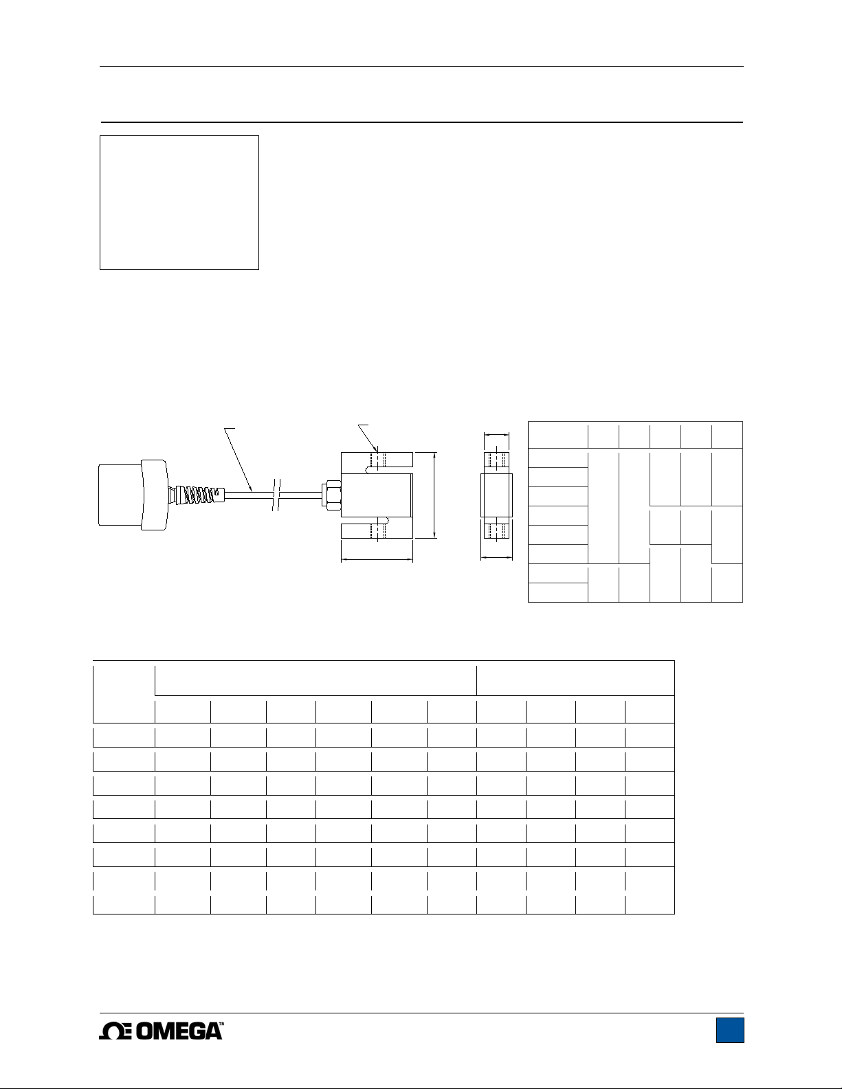
4 SERIES RLC01 FORCE SENSORS
4.1 Unpacking and Assembly
Carefully remove the sensor from the box. No assembly is required.
4.2 Overview
Tension and compression force may be applied to the surfaces with threaded
holes. Attachments may be threaded into these holes. These holes also
allow for mounting as required.
4.3 Specifications
Accuracy: ±0.15% of full scale
Safe overload: 150% of full scale
Operating temperature: 40ºF – 100ºF [5ºC – 38ºC]
Operating humidity: 96% max. (non-condensating)
Weight: 1.9 to 3.0 lb [0.9 to 1.4 kg], depending on model
4.4 Dimensions
4.5 Capacity x Resolution
(in[mm])
20 FT [6M] LONG
E X2
B
C
Model No. A B C D E
RLC01-50
RLC01-100
A
RLC01-200
RLC01-500
RLC01-1K
D
RLC01-2K
RLC01-5K
RLC01-10K
2.40
[61.0]
3.90
[99.1]
2.00
[50.8]
3.00
[76.2]
0.46
[11.7]
0.71
[18.0]
0.96
[24.4]
0.65
[16.5]
0.90
[22.9]
1.15
[29.2]
1/4-28
UNF
1/2-20
UNF
3/4-16
UNF
With Model DFG-RS5 Indicator With Model DFG-RS3 Indicator
Model No.
lbF ozF gF kgF N kN lbF kgF N kN
RLC01-50 50 x 0.02 800 x 0.5 25000 x 10 25 x 0.01 250 x 0.1 - 50 x 0.05 25 x 0.02 250 x 0.2 -
RLC01-100 100 x 0.05 1600 x 1 50000 x 20 50 x 0.02 500 x 0.2 - 100 x 0.1 50 x 0. 05 500 x 0.5 -
RLC01-200 200 x 0.1 3200 x 2 - 100 x 0.05 1000 x 0.5 1 x 0.0005 200 x 0.2 100 x 0. 1 1000 x 1 -
RLC01-500 500 x 0.2 8000 x 5 - 250 x 0.1 2500 x 1 2.5 x 0.001 500 x 0.5 250 x 0.2 2500 x 2 -
RLC01-1K 1000 x 0.5 16000 x 10 - 500 x 0.2 5000 x 2 5 x 0.002 1000 x 1 500 x 0.5 5000 x 5 -
RLC01-2K 2000 x 1 32000 x 20 - 1000 x 0.5 10000 x 5 10 x 0.005 2000 x 2 1000 x 1 10000 x 10 -
RLC01-5K 5000 x 2 - - 2500 x 1 25000 x 10 25 x 0.01 5000 x 5 2500 x 2 - 25 x 0.02
RLC01-10K 10000 x 5 - - 5000 x 2 50000 x 25 50 x 0.02 10000 x 10 5000 x 5 - 50 x 0.05
6
Page 8
Force & Torque Sensors For DFG-RS3 / DFG-RS5 Indicators User’s Guide
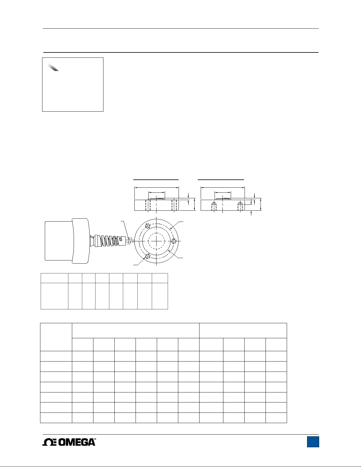
5 SERIES RLC02 FORCE SENSORS
5.1 Unpacking and Assembly
Carefully remove the sensor from the box. No assembly is required.
5.2 Overview
Compression force may be applied to the button in the center of the top surface
of the sensor (visible in the picture above). DO NOT apply load to the cover on
the underside of the sensor. Threaded holes are supplied to permit mounting to
various surfaces.
5.3 Specifications
Accuracy: ±0.5% of full scale
Safe overload: 150% of full scale
Operating temperature: 40ºF – 100ºF [5ºC – 38ºC]
Operating humidity: 96% max. (non- condensating)
Weight: RLC02-100 - RLC02-2K: 0.3 lb [0.1 kg]
RLC02-5K - RLC02-10K: 0.5 lb [0.2 kg]
5.4 Dimensions
(in[mm])
RLC02-100 – RLC02-2K RLC02-5K – RLC02-10K
ØA
ØB
C
ØA
ØB
C
10 FT [3 M] LONG
#6-32 X3
D
ØE
ØG
DO NOT APPLY LOAD
INSIDE THIS AREA
D
F
Model ØA ØB C D ØE F ØG
RLC02-100 –
RLC02-2K
RLC02-5K –
RLC02-10K
1.23
[31.3]
1.48
[37.6]
0.32
[8.1]
0.43
[10.9]
0.05
[1.3]
0.07
[1.8]
0.39
[9.9]
0.62
[15.8]
1.0
[25.4]
1.25
[31.8]
-
0.25
[6.4]
0.83
[21.1]
1.08
[27.4]
5.5 Capacity x Resolution
With Model DFG-RS5 Indicator With Model DFG-RS3 Indicator
Model No.
lbF ozF gF kgF N kN lbF kgF N kN
RLC02-100 100 x 0.05 1600 x 1 50000 x 20 50 x 0.02 500 x 0. 2 - 100 x 0.1 50 x 0.05 500 x 0.5 -
RLC02-200 200 x 0.1 3200 x 2 - 100 x 0.05 1000 x 0.5 1 x 0.0005 200 x 0.2 100 x 0.1 1000 x 1 -
RLC02-500 500 x 0.2 8000 x 5 - 250 x 0.1 2500 x 1 2.5 x 0.001 500 x 0.5 250 x 0.2 2500 x 2 -
RLC02-1K 1000 x 0.5 16000 x 10 - 500 x 0.2 5000 x 2 5 x 0.002 1000 x 1 500 x 0.5 5000 x 5 -
RLC02-2K 2000 x 1 32000 x 20 - 1000 x 0.5 10000 x 5 10 x 0.005 2000 x 2 1000 x 1 10000 x 10 -
RLC02-5K 5000 x 2 - - 2500 x 1 25000 x 10 25 x 0.01 5000 x 5 2500 x 2 - 25 x 0.02
RLC02-10K 10000 x 5 - - 5000 x 2 50000 x 25 50 x 0.02 10000 x 10 5000 x 5 - 50 x 0.05
7
Page 9
Force & Torque Sensors For DFG-RS3 / DFG-RS5 Indicators User’s Guide
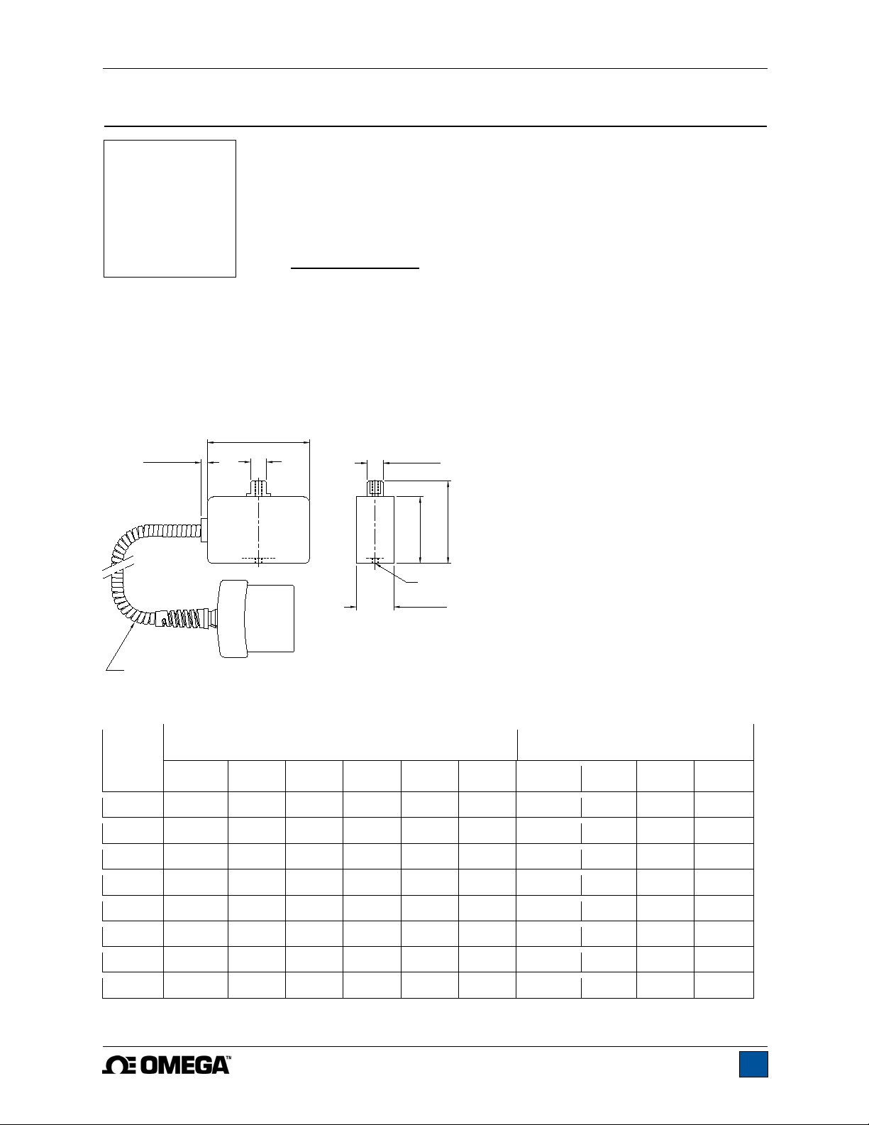
6 SERIES RLC03 FORCE SENSORS
6.1 Unpacking and Assembly
Carefully remove the sensor from the box. Extra care should be taken for very low
capacity models. No assembly is required.
6.2 Overview
Tension and compression force may be applied to the threaded holes in the load
cell shaft and opposite flat surface. Attachments may be threaded into these
holes. Finger-tighten only. These holes also allow for mounting as required.
6.3 Specifications
Accuracy: ±0.15% of full scale
Safe overload: RLC03-0.25 – RLC03-2: 200% of full scale
RLC03-5 – RLC03-100: 150% of full scale
Operating temperature: 40ºF – 100ºF [5ºC – 38ºC]
Operating humidity: 96% max. (non-condensating)
Weight: 0.4 lb [0.2 kg]
6.4 Dimensions
0.16 [4.1]
(in[mm])
2.50 [63.5]
0.31 [7.9]
Ø 0.44 [11.2]
2.06 [52.3]
1.83 [46.5]
#10-32 X2
0.81 [20.6]
24.0 [610] RETRACTED LENGTH
6.5 Capacity x Resolution
Model
No.
RLC03-0.25 0.25 x 0.0001 4 x 0.002 100 x 0.05 - 1 x 0.0005 1000 x 0.5 0.25 x 0.0002 100 x 0.1 - 1 x 0.001
RLC03-0.5 0.5 x 0.0002 8 x 0.005 250 x 0.1 - 2.5 x 0.001 2500 x 1 0.5 x 0.0005 250 x 0.2 - 2.5 x 0.002
RLC03-2 2 x 0.001 32 x 0.02 1000 x 0.5 1 x 0.0005 10 x 0.005 - 2 x 0.002 - 1 x 0.001 10 x 0.01
RLC03-5 5 x 0.002 80 x 0.05 2500 x 1 2.5 x 0.001 25 x 0.01 - 5 x 0.005 - 2.5 x 0.002 25 x 0.02
RLC03-10 10 x 0.005 160 x 0.1 5000 x 2 5 x 0.002 50 x 0.02 - 10 x 0.01 - 5 x 0.005 50 x 0.05
RLC03-20 20 x 0.01 320 x 0.2 10000 x 5 10 x 0.005 100 x 0.05 - 20 x 0.02 - 10 x 0.01 100 x 0.1
lbF ozF gF kgF N mN lbF gF kgF N
With Model DFG-RS5 Indicator With Model DFG-RS3 Indicator
RLC03-50 50 x 0.02 800 x 0.5 25000 x 10 25 x 0. 01 250 x 0.1 - 50 x 0.05 - 25 x 0.02 250 x 0.2
RLC03-100 100 x 0.05 1600 x 1 50000 x 20 50 x 0.02 500 x 0.2 - 100 x 0.1 - 50 x 0.05 500 x 0.5
8
Page 10
Force & Torque Sensors For DFG-RS3 / DFG-RS5 Indicators User’s Guide
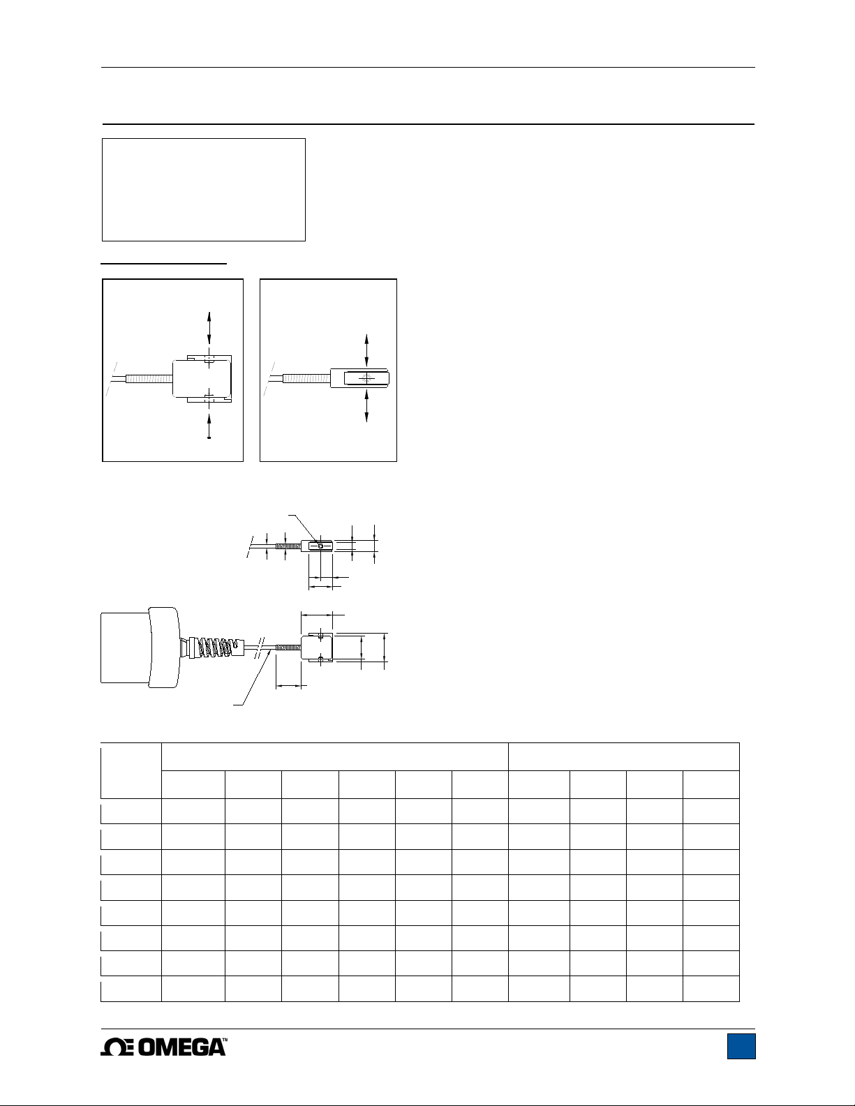
7 SERIES R04 FORCE SENSORS
7.1 Unpacking and Assembly
Carefully remove the sensor from the box. Extra care should be taken
for very low capacity models. No assembly is required.
7.2 Overview
Tension and compression force may be applied to the surfaces with
threaded holes. Attachments may be threaded into these holes.
Finger-tighten only. These holes also allow for mounting as required.
7.3 Specifications
Accuracy: ±0.2% of full scale
Safe overload: 200% of full scale
Operating temperature: 40ºF – 100ºF [5ºC – 38ºC]
Operating humidity: 96% max. (non-condensating)
Weight: 0.015 lb [0.007 kg]
7.4 Dimensions
(in[mm])
0.110 [2.8] DEEP
#4-40 UNC
X2
0.20 [4.7]
0.30 [7.6]
0.32 [8.1]
0.65 [16.5]
0.63 [16.0]
0.85 [21.2]
0.60 [15.2]
0.75 [19.1]
5 FT [1.5m] LONG
Ø0.08 [2.1]
Ø0.13 [3.2]
7.5 Capacity x Resolution
Model
No.
RLC04-0.25 0.25 x 0.0001 4 x 0.002 100 x 0.05 - 1 x 0.0005 1000 x 0.5 0.25 x 0.0002 100 x 0.1 - 1 x 0.001
RLC04-0.5 0.5 x 0.0002 8 x 0.005 250 x 0.1 - 2.5 x 0.001 2500 x 1 0.5 x 0.0005 250 x 0.2 - 2.5 x 0.002
RLC04-2 2 x 0.001 32 x 0.02 1000 x 0.5 1 x 0.0005 10 x 0.005 - 2 x 0.002 - 1 x 0.001 10 x 0.01
RLC04-5 5 x 0.002 80 x 0.05 1000 x 0.5 2.5 x 0.001 25 x 0.01 - 5 x 0.005 - 2.5 x 0.002 25 x 0.02
RLC04-10 10 x 0.005 160 x 0.1 5000 x 2 5 x 0.002 50 x 0.02 - 10 x 0.01 - 5 x 0.005 50 x 0.05
RLC04-20 20 x 0.01 320 x 0.2 10000 x 5 10 x 0.005 100 x 0.05 - 20 x 0.02 - 10 x 0.01 100 x 0.1
RLC04-50 50 x 0.02 800 x 0.5 25000 x 10 25 x 0.01 250 x 0.1 - 50 x 0.05 - 25 x 0.02 250 x 0.2
lbF ozF gF kgF N mN lbF gF kgF N
With Model DFG-RS5 Indicator With Model DFG-RS3 Indicator
RLC04 -100 100 x 0.05 1600 x 1 50000 x 20 50 x 0.02 500 x 0.2 - 100 x 0.1 - 50 x 0.05 500 x 0.5
9
Page 11
Force & Torque Sensors For DFG-RS3 / DFG-RS5 Indicators User’s Guide
8 SERIES R50 TORQUE SENSORS
8.1 Unpacking and Assembly
Carefully remove the sensor from the box. For models RTQ50-10Z,
RTQ50-20Z, and RTQ50-50Z, remove the protective tubing inserted
around the chuck. Save it for future transportation needs. No assembly is
required.
8.2 Overview
Designed for clockwise and counter-clockwise torque testing. The sensor
may be handheld or mounted to a test stand, fixture, or other equipment. Bits or fixtures may be placed in
the chuck, although extra care should be taken when handling low capacity models.
8.3 Specifications
Accuracy: ±0.35% of full scale
Safe overload: RTQ50-10Z - RTQ50-50Z: 300% of full scale
RTQ50-12 - RTQ50-100: 150% of full scale
Chuck opening range: RTQ50-10Z - RTQ50-50Z: 0.062 - 0.375 in [1.6 - 9.5 mm]
RTQ50-12 - RTQ50-100: 0.078 - 0.5 in [2.0 - 12.7 mm]
Operating temperature: 40ºF – 100ºF [5ºC – 38ºC]
Operating humidity: 96% max. (non-condensating)
Weight: From 1.4 lb [0.6 kg]
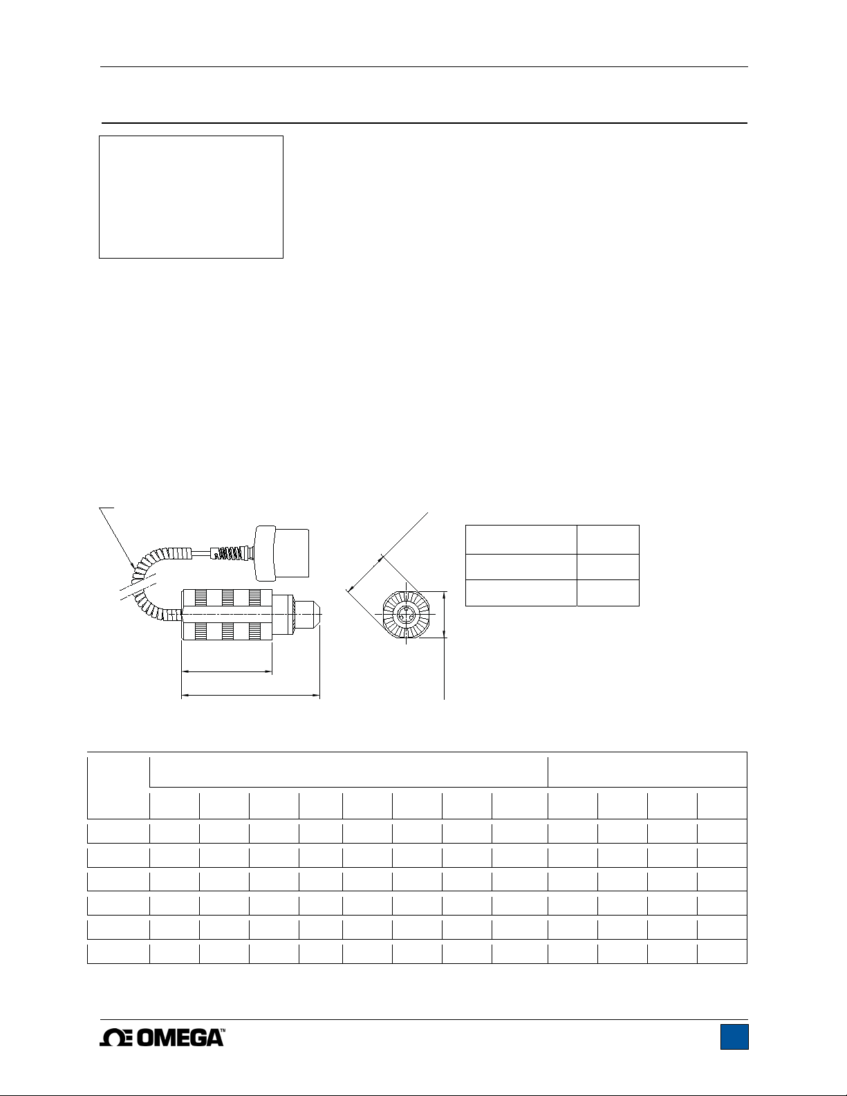
8.4 Dimensions
24.0 [610.0] RETRACTED LENGTH
8.5 Capacity x Resolution
(in[mm])
3.50 [88.9]
Ø 1.75 [44.4]
Model No. A
RTQ50-10Z - RTQ50-50Z 4.82 [122.4]
RTQ50-12 - RTQ50-100 5.19 [131.8]
A
1.69 [42.4] X2
Model No.
ozFin lbFin lbFft gFcm kgFmm Nmm Ncm Nm ozFin lbFin kgFmm Ncm
RTQ50-10Z 10 x 0.005
RTQ50-20Z 20 x 0.01
RTQ50-50Z 50 x 0.02
RTQ50-12
RTQ50-50
RTQ50-100
-
-
-
With Model DFG-RS5 Indicator With Model DFG-RS3 Indicator
-
-
-
12 x 0.005 1 x 0.0005 -
50 x 0.02 4 x 0.002
100 x 0.05 8 x 0.005
-
700 x 0.5 7 x 0.005 70 x 0.05 7 x 0.005
-
1400 x 1 14 x 0.01 140 x 0.1 14 x 0.01
-
3600 x 2 36 x 0.02 350 x 0.2 35 x 0.02
140 x 0.1
-
- 1150 x 0.5
580 x 0.5
-
135 x 0.1 1.35 x 0.001
-
570 x 0.5 5.7 x 0.005
-
1150 x 0.5 11.5 x 0.005
-
10 x 0.01
-
20 x 0.02
-
50 x 0.05
-
-
-
-
12 x 0.01 140 x 0.1 135 x 0.1
50 x 0.05 580 x 0.5 570 x 0.5
100 x 0.1 1150 x 1 1150 x 1
7 x 0.005 7 x 0.005
-
14 x 0.01 14 x 0.01
-
36 x 0.05 35 x 0.05
10
Page 12
Force & Torque Sensors For DFG-RS3 / DFG-RS5 Indicators User’s Guide
11
Page 13
Force & Torque Sensors For DFG-RS3 / DFG-RS5 Indicators User’s Guide
M-5253/1017
12
 Loading...