

Page 1
REMOTE PROBE HUMIDITY/
TEMPERATURE TRANSMITTER
SERIES
Installation & Operation Instructions
Phone: 1-888-967-5224
Website: workaci.com
GENERAL INFORMATION
The A/TT Remote Probe Series sensors and
transmitters are single point sensors that
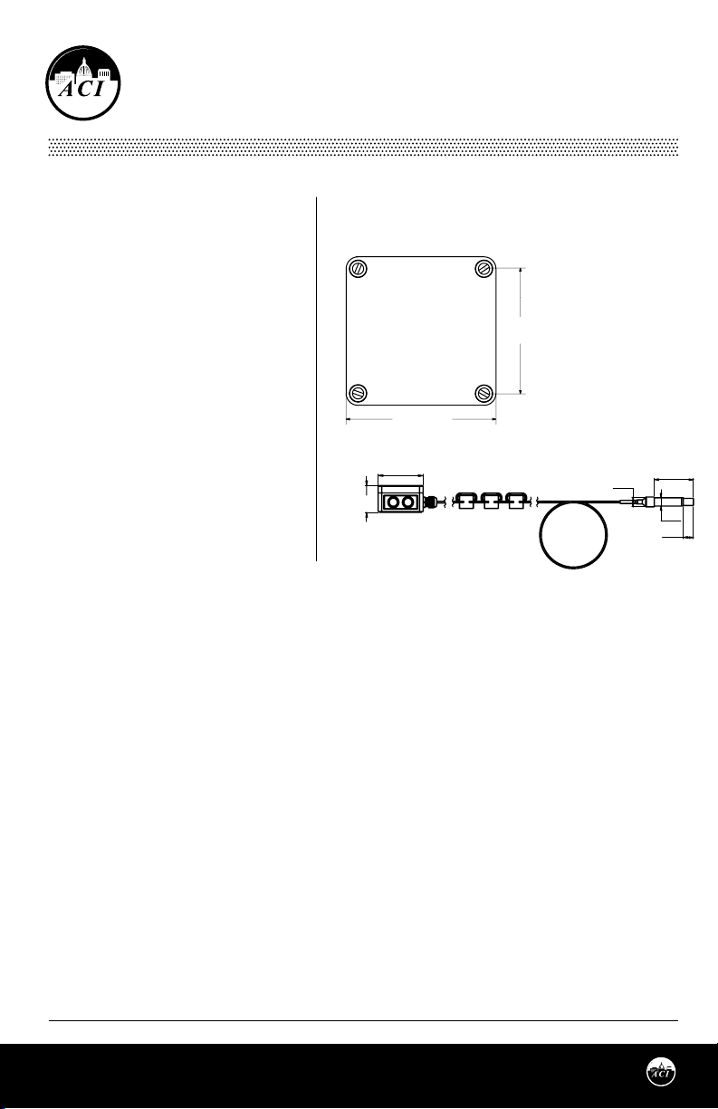
FIGURE 1: ENCLOSURE
DIMENSIONS
NEMA 4X (-4X)
output 4-20 mA with an optional voltage
signal output of 1-5VDC or 2-10VDC signal.
The sensor is designed for use with electronic
controllers in commercial heating and
cooling building management systems. All
A/TT temperature transmitters can be
3.11"
(78.99 mm)
powered from either an unregulated or
regulated 8.5-32 VDC power supply.
The A/RH Remote Probe Series sensor is a
3.70"
(93.98 mm)
relative humidity transmitter that can be
powered with either an AC or DC supply
voltage. The RH Remote Probe transmitter is
eld selectable with a 4-20 mA, 0-5 VDC, or
0-10 VDC output signal that is equivalent to 0
to 100% RH. All RH units are shipped from the
factory set to 4-20 mA output.
2.21”
(56.07mm)
3.70”
(93.98mm)
0.90”
(22.78mm)
(19.05mm)
(90.42mm)
0.75”
(23.11mm)
3.56”
0.91”
For optimal readings, follow these tips:
• Do not install on external walls.
• Avoid air registers, diusers, vents, and windows.
• Eliminate and seal all wall and conduit penetrations. Air migration from wall cavities may alter temperature readings.
• Do not install near heat sources. eg: lamps, radiators, direct sunlight, copiers, chimney walls, walls concealing
hot-water pipes.
MOUNTING INSTRUCTIONS
Remote Probe sensors may be mounted using a 3/4” mounting clip(not included) on walls or with cable
ties. The sensor should be mounted in an area where air circulation is well mixed and not blocked by
obstructions.
The RH Remote Probe includes a Black Rubber Cap that ts over the sensor lter. This cap should be placed
on the sensor lter during wet/wash down processes. The cap must be removed for normal operation.
TRANSMITTER MOUNTING
Attach the base directly to the wall by rst drilling pilot holes for the mounting screws. Alternatively, you
may refer to the dimensions listed in FIGURE 1 (top) to measure out.
SENSOR MOUNTING
To x the probe on a wall, ACI recommends a height of 48-60” (1.2-1.5 m) o the ground and at least 1.5’ (0.5
m) from the adjacent wall. Slide the sensor probe through the mounting clip(not included) - see FIGURE 2
(p. 2). Drill a screw through the socket and tighten to the wall. Refer to Wiring Instructions (p. 2-4) to make
necessary connections.
Page 1
Automation Components, Inc.
2305 Pleasant View Road | Middleton, WI 53562
Phone: 1-888-967-5224 | Website: workaci.com
Version: 7.0
I0000829
Page 2
WIRING INSTRUCTIONS
PRECAUTIONS
VAC
• RH Transmitter can be powered by VAC or VDC.
• Temperature transmitter is powered by 24 VDC
only.
• Remove power before wiring. Never connect or
disconnect wiring with power applied.
• Shielding - When using a shielded cable, ground
the shield at the Transmitter ONLY. Do NOT
ground the shield at the controller. Grounding
both ends can cause a ground loop. The shield
needs to be terminated into the Com terminal.
• It is recommended you use an isolated UL-listed
class 2 transformer when powering the unit with
24 VAC. Failure to wire the devices with the correct
polarity when sharing transformers may result in
damage to any device powered by the shared
transformer.
• If the 24 VDC or 24VAC power is shared with devices
that have coils such as relays, solenoids, or other
inductors, each coil must have an MOV, DC/AC
Transorb, Transient Voltage Suppressor (ACI Part:
142583), or diode placed across the coil or inductor.
The cathode, or banded side of the DC Transorb or
diode, connects to the positive side of the power
supply. Without these snubbers, coils produce very
large voltage spikes when de-energizing that can
cause malfunction or destruction of electronic
circuits.
TEMPERATURE
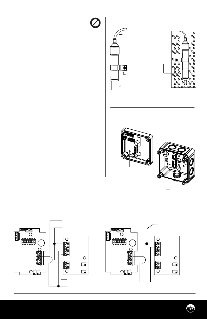
The PG11 cord grip cap is shipped loosely tightened.
Make sure that is loose when you open the cover. This is
the cord grip that the remote sensor goes to.
FIGURE 2: MOUNTED ASSEMBLY
Minimum Wire Bend Radius
1.92” (48.77 mm)
Plastic cover MUST be used
for washdown applications.
REMOVE for normal operation.
3/4” MOUNTING CLIP
NOT INCLUDED
SINTERED FILTER
FIGURE 3: PRINTED CIRCUIT
BOARDS
RH PCB
Open the cover of the enclosure. The temperature
transmitter is located on the bottom of the enclosure.
ACI recommends 16 to 26 AWG twisted pair wires or
TEMPERATURE TRANSMITTER BOARD
shielded cable for all transmitters.
FIGURE 4: SHARED POWER CONNECTIONS and ANALOG OUTPUTS
VOLTAGE OUTPUTS
VOUT
COM
VIN
4-20mA
Automation Components, Inc.
2305 Pleasant View Road | Middleton, WI 53562
Phone: 1-888-967-5224 | Website: workaci.com
RH VOUT OUTPUT
+24V DC
+
-
GND
VOUT
TEMPERATURE TRANSMITTER
VOUT OUTPUT
24V DC (-) COMMON &
SHIELD CONNECTION
CURRENT OUTPUTS
VOUT
COM
VIN
4-20mA
RH 4-20mA
OUTPUT
Page 2
CAN SHARE 24V DC
+
-
TEMPERATURE TRANSMITTER
4-20mA OUTPUT
SHIELD CONNECTION
Version: 7.0
I0000829
Page 3
P
+ -
+ -
+ -
Temp.Transmitter #1
Temp.Transmitter #N
Temp.Transmitter #2
-
VDC
+
Controller
= Connections
In1 = Controller Input #1
In2 = Controller Input #2
In3 = Controller Input #3
WIRING INSTRUCTIONS (Continued)
TEMPERATURE (Continued)
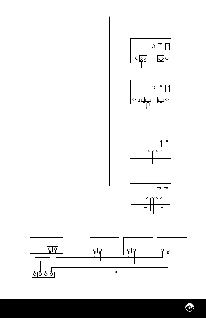
Twisted pair may be used for 2-wire current output
transmitters or 3-wire for voltage output. Refer to
FIGURE 5 (top) for wiring diagrams. All wiring must
comply with local and National Electric Codes. All ACI
TT and TTM temperature transmitters can be powered
from either an unregulated or regulated 8.5 to 32VDC
power supply. The TT and TTM DO NOT support an AC
input. All TT and TTM temperature transmitters are
reverse polarity protected. After wiring, attach the
cover to the enclosure.
FIGURE 5: TEMPERATURE WIRING
STANDARD UNITS
CURRENT OUTPUT (4 to 20 mA)
ZERO
SPAN
RTD
-
+
4 to 20mA Output
+VDC
VOLTAGE OUTPUT (1-5 or 2-10 VDC)
SPANZERO
The minimum voltage at the transmitter power
terminal is 8.5V after load resistor voltage drop.
• 249 Ω load resistor (1-5 VDC output) =
13.5 V min supply voltage
• 499 Ω load resistor (2-10 VDC output) =
18.5 V min supply voltage
Note: All RTD’s are supplied with (2) or (3) ying lead
POTTED UNITS
CURRENT OUTPUT (4 to 20 mA)
wires. ACI’s transmitters are supplied with a 2 pole
terminal block for RTD sensor connections. When wiring a
3 wire RTD, connect the (2) common wires (same color)
together into the same terminal block - see FIGURE 4
(p.2).
+VDC (Red Wire)
4 to 20mA Output
TEMPERATURE - MULTIPLE CONNECTIONS
Several transmitters may be powered from the same
VOLTAGE OUTPUT (1-5 or 2-10 VDC)
supply as shown in FIGURE 6 (bottom). Each
transmitter draws 25mA; refer to the following
equation to obtain the number of permissible
transmitters: [# Transmitters] = [Current] / (25 mA).
+VDC (Red Wire)
GND (White Wire)
Voltage Output
FIGURE 6: MULTIPLE TRANSMITTER CONNECTIONS
ower Supply
+
(White Wire)
(Yellow Wire)
-
GND
VOUT
Voltage Output (1-5, 2-10 VDC)
GND
+VDC
RTD
SPANZERO
RTD Wires
(100 Ohm RTD Brown Wires)
(1K Ohm RTD Black Wires)
SPAN
ZERO
RTD Wires
(100 Ohm RTD Brown Wires)
(1K Ohm RTD Black Wires)
Gnd In1 In2 In3
Automation Components, Inc.
2305 Pleasant View Road | Middleton, WI 53562
Phone: 1-888-967-5224 | Website: workaci.com
Page 3
Version: 7.0
I0000829
Page 4
WIRING INSTRUCTIONS
(Continued)
RELATIVE HUMIDITY WIRING INSTRUCTIONS
Open the cover of the enclosure. The RH
transmitter is located on the inside of the cover.
ACI recommends 16 to 26 AWG twisted pair wires
or shielded cable for all transmitters. Twisted pair
may be used for 2-wire current output
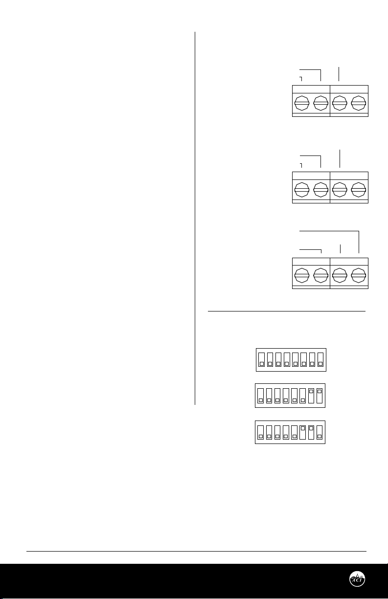
transmitters or 3-wire for voltage output. Refer to
FIGURE 7 (top) for wiring diagrams.
RH OUTPUT SIGNALS
Switches 6, 7, and 8 are used to set the RH output
signal. Refer to FIGURE 8 (bottom) for switch
settings.
HUMIDITY REVERSE ACTING OUTPUT
The output is direct acting and can be changed
to reverse acting mode. The output range stays
the same but the corresponding RH value is
opposite.
Example:
Direct Acting (DA)
0-10 V output mode,
0 V = 0% RH and 10 V =
100% RH
Reverse Acting (RA)
0-10 V output mode,
0 V = 100% and 10 V = 0%
To change the transmitter to reverse acting or
back to direct acting, set switch 4 to ON to put
the unit in setup mode. After switch 4 is on,
turning switch 2 to ON will put the unit in
direct/reverse acting mode. When switch 2 is set
to ON, the output can be used to show if the unit
is in direct or reverse acting mode. For direct
acting, the output will be 1 V for 0-5 V, 2 V for 0-10
V, and 7.2 mA for 4-20 mA. For reverse acting the
output will be 4 V for 0-5 V, 8 V for 0-10 V, and 16.8
mA for 4-20 mA.
FIGURE 7: RH OUTPUT SIGNALS
2 WIRE CURRENT OUTPUT SIGNAL
DC SUPPLY VOLTAGE
4-20 mA OUTPUT
4-20mA
3 WIRE CURRENT OUTPUT SIGNAL
SUPPLY GROUND / SIGNAL COMMON / SHIELD CONNECTION
AC or DC SUPPLY VOLTAGE
4-20 mA OUTPUT
4-20mA
VOLTAGE OUTPUT SIGNAL
0-10 or 0-5 VDC OUTPUT SIGNAL
SUPPLY GROUND / SIGNAL COMMON / SHIELD CONNECTION
AC or DC SUPPLY VOLTAGE
4-20mA
FIGURE 8: RH OUTPUT SWITCHES
4-20 mA Output
ON
ON
2 3
OFF
ON
OFF
ON
OFF
1
ON
1
ON
1 4 5 6
5 6 7
4 8
0-10 VDC Output
3
2
4
5
0-5 VDC Output
2 3
7
6
7 8
SHIELD CONNECTION
TB1
COMVIN VOUT
TB1
COMVIN VOUT
TB1
COMVIN VOUT
8
With switches 2 and 4 ON, each time switch 5 is set
to ON the output will change to reverse acting or
direct acting. To reset the unit to the default setting, toggle both switches 5 and 6 ON then OFF while both
switches 2 and 4 are ON. When all calibration is completed, remember to place the switches back into the
positions that correspond to the output needed as shown in FIGURE 8 (bottom).
RH CALIBRATION INSTRUCTIONS
Note: This is only a single point calibration. All transmitters are factory calibrated to meet/exceed
published specications. Field adjustment should not be necessary.
Page 4
Automation Components, Inc.
2305 Pleasant View Road | Middleton, WI 53562
Phone: 1-888-967-5224 | Website: workaci.com
Version: 7.0
I0000829
Page 5
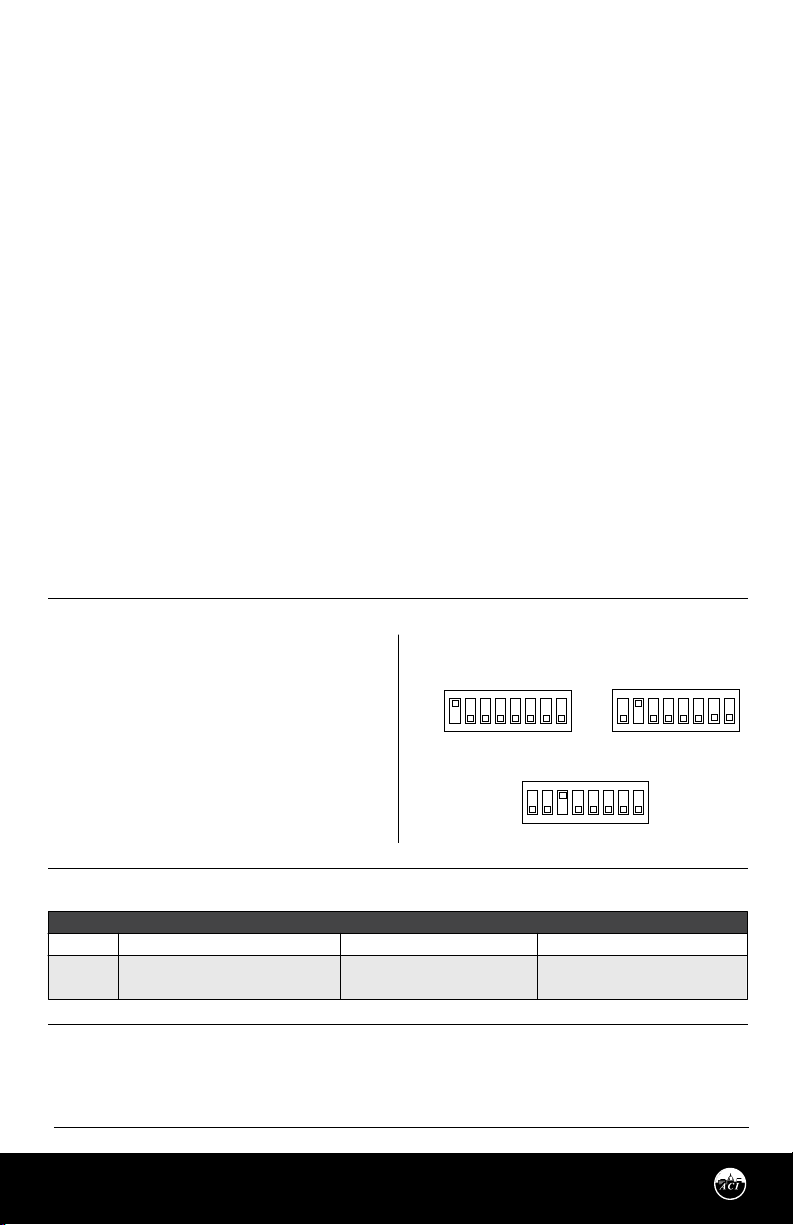
RH CALIBRATION INSTRUCTIONS (Continued)
The dipswitch allows the user to calibrate the sensor through the software. Setting switch 4 ON will put the
transmitter into setup mode allowing the increment and decrement to work. Once in setup mode, the
output will change to 50% (2.5 V for 0-5 V, 5 V for 0-10 V, 12 mA for 4-20 mA). Each increment or decrement
step will cause the output to change by 0.1 V for 0-5 V, 0.2 V for 0-10 V, and 0.32 mA for 4-20 mA in setup
mode. This can be used to show the user how far oset the transmitter is. To see the starting point again set
switch 1 ON. This will show the 50% output again. When the unit is out of setup mode the output will go
back to RH output. The maximum oset is 10%. There can be a total of 20 increments.
Increment RH Output
This will shift the RH output linearly up in 0.5% steps. Switch 4 must be set to ON rst. After switch 4 is on,
each time switch 5 is set ON the RH output will increase by 0.5%. The increase goes into eect each time
switch 5 is set to ON.
Decrement RH Output
This will shift the RH output linearly down in 0.5% steps. Switch 4 must be set to ON rst. After switch 4 is
on, each time switch 6 is set ON the RH output will decrease by 0.5%. The decrease goes into eect each
time switch 6 is set to ON.
Reset RH Output
This will reset the RH output back to the original calibration. Switch 4 must be set to ON rst. After switch 4
is on, toggle switches 5 and 6 ON then OFF. After 5 and 6 are OFF, slide switch 4 OFF. When all calibration is
completed, remember to place the switches back into the positions that correspond to the output needed
as shown in FIGURE 8 (p. 4).
RH TEST INSTRUCTIONS
Test mode will make the transmitter output a
FIGURE 9: RH SELECTION SWITCHES
xed 0%, 50%, or 100% value. The sensor will not
aect the transmitter output. This is used for
troubleshooting or testing only.
ON
OFF
0% RH Output
ON
2 3
5 6
1
4
7
8
ON
OFF
ON
1
50% RH Output
3
2
4
5
6
7
8
Switches 1, 2, and 3 are used for test mode. The
output will be a xed 0%, 50%, or 100% signal
that corresponds to the output selected with
switches 6, 7, and 8. Refer to FIGURE 9 (right) for
100% RH Output
ON
ON
1 4 5 6
OFF
2 3
7 8
switch settings.
RH CONVERSION FORMULAS
Formula:
Example:
4-20 mA
([mA signal] -4) / 0.16 = percent RH
12 mA output signal
(12 - 4) / 0.16 = 50% RH
[VDC signal] / 0.05 = percent RH
1.25 vdc output signal
1.25 / 0.05 = 25% RH
0-5 VDC
0-10 VDC
[VDC signal] / 0.10 = percent RH
7.50 vdc output signal
7.50 / 0.10 = 75% RH
WARRANTY
The ACI Remote Probe Series RH sensors are covered by ACI’s Five (5) Year Limited Warranty, which is
located in the front of ACI’S SENSORS & TRANSMITTERS CATALOG or can be found on ACI’s website:
www.workaci.com.
Page 5
Automation Components, Inc.
2305 Pleasant View Road | Middleton, WI 53562
Phone: 1-888-967-5224 | Website: workaci.com
Version: 7.0
I0000829
Page 6
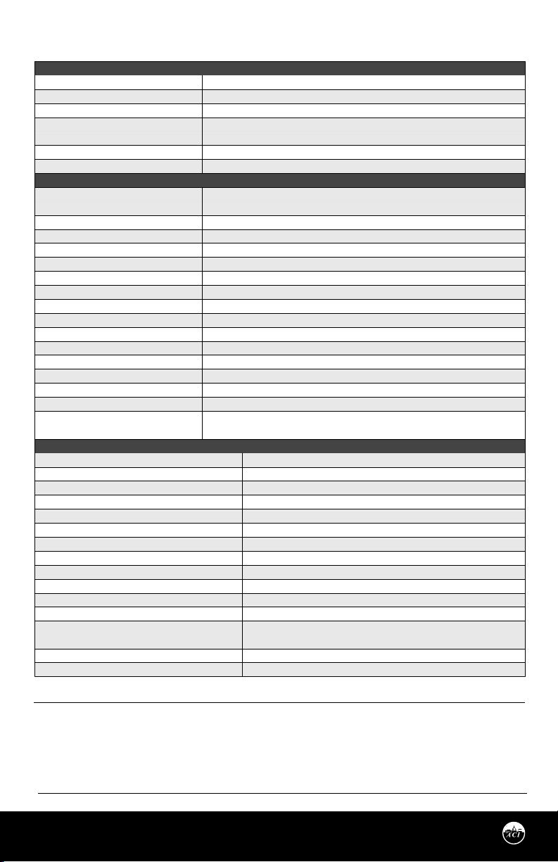
PRODUCT SPECIFICATIONS
CABLE & ENCLOSURE
Minimum Cable Bend Radius:
Cable Ratings | Cable Jacket Material:
Cable Operating Temperature Range:
Enclosure Specications: (Material,
Flammability, Temp., NEMA/IP Ratings):
Sensing Tube Material:
Filter Material:
RH TRANSMITTER
RH Supply Voltage
(Reverse Polarity Protected):
RH Supply Current (VA):
RH Output Load Resistance:
RH Output Signal:
RH Accuracy @ 77°F (25°C):
RH Measurement Range:
Operating RH Range:
Operating Temperature Range:
Storage Temperature Range:
RH Stability | Repeatability | Sensitivity:
RH Response Time (T63):
RH Sensor Type:
RH Transmitter Stabilization Time:
RH Connections | Wire Size:
RH Terminal Block Torque Rating:
RH NIST Test Points:
TEMPERATURE TRANSMITTER
TT Supply Voltage:
Supply Current:
TT Maximum Load Resistance:
TT Output Signals:
TT Calibrated Accuracy | Linearity ¹:
TT Temperature Drift ²:
TTM100/TTM1K Certication Points:
TT Warm Up Time:
Warm Up Drift:
Transmitter Operating Temperature/RH Range:
Platinum RTD (PTC) Number Wires | Wire Colors:
Platinum RTD Sensor Output @ 32°F (0°C):
Platinum RTD Tolerance Class | Accuracy:
Platinum RTD Sensor Stability:
Platinum RTD Response Time (63% Step Change):
Note : A Transmitter is calibrated at 71ºF (22ºC) Nominal | Note : Temperature Drift is referenced to 71ºF nominal calibration temperature
1.92” (48.77 mm) or 10x the Cable Diameter
UL (CMP, CL3P, FPLP); CSA(CMP, FT6), Plenum Rated | Polyvinyl Chloride (PVC)
32 to 167 °F (0 to 75 °C)
“-4X” Enclosure: ABS Plastic; UL94-V0; -40 to 140 °F (-40 to 60 °C)
304 Series Stainless Steel
304 Series Stainless Steel
4-20 mA: 250 Ω Load: 15 - 40 VDC / 18 - 28 VAC | 500 Load: 18 - 40 VDC / 18 - 28 VAC
0-5 VDC: 12 - 40 VDC / 18 - 28 VAC | 0-10 VDC: 18 - 40 VDC / 18 - 28 VAC
Voltage Output: 8 mA maximum (0.32 VA) | Current Output: 24 mA maximum (0.83 VA)
4-20 mA: 700 Ω maximum | 0-5 VDC or 0-10 VDC: 4 KΩ Minimum
2-wire: 4 - 20 mA (Default) | 3-wire: 0-5 or 0-10 VDC & 4 - 20 mA (Field Selectable)
+/- 1% over 20% RH Range between 20 to 90% | +/- 2%, 3%, or 5% from 10 to 95%
0-100%
0 to 95% RH, non-condensing (Conformally Coated PCB’s)
-40 to 140 °F (-40 to 60 °C)
-40 to 149 °F (-40 to 65 °C)
Less than 2% drift / 5 years | 0.5% RH | 0.1% RH
20 Seconds Typical
Capacitive with Hydrophobic Filter
30 Minutes (Recommended time before doing accuracy verication)
Screw Terminal Blocks (Polarity Sensitive) | 16 (1.31 mm²) to 26 AWG (0.129 mm²)
4.43 to 5.31 lb-in (0.5 to 0.6 Nm)
Default Test Points: 3 Points (20%, 50% & 80%) or 5 Points (20%, 35%, 50%, 65% & 80%)
1% NIST Test Points: 5 Points within selected 20% Range (ie. 30%-50% are 30, 35, 40, 45 & 50)
+8.5 to 32 VDC (Reverse Polarity Protected); 25 mA minimum
Load: +13.5 to 32 VDC | 500 Load: +18.5 to 32 VDC
250
(Terminal Voltage – 8.5 V ) | 0.020 A
2-Wire: 4-20 mA Current Output | 3-Wire: 1-5 VDC/2-10 VDC Voltage Output
T. Spans < 500 °F (260 °C): +/- 0.2% | T. Spans > 500 °F (260 °C): +/- 0.5%
T. Spans < 100 °F (38 °C): +/- 0.04%/°F | T. Spans > 100 °F (38 °C): +/- 0.02%/°F
3 Point NIST: 20, 50, 80% of span | 5 Point NIST: 20, 35, 50, 65, & 80% of span
10 Minutes | +/- 0.1%
-40 to 185 °F (-40 to 85 °C)
0 to 90% RH, non-condensing
Two | TT100 & TTM100: Brown/Brown | TT1K & TTM1K: Black/Black
A/TT100/TTM100 Series: 100
+/- 0.06% Class A | Tolerance Formula: +/- °C = (0.15 °C + (0.002 * |t|),
where |t| is the absolute value of Temperature above or below 0°C in °C)
+/-0.03% after 1000 Hours @ 572 °F (300 °C)
8 Seconds nominal
Ω
| A/TT1K/TTM1K Series: 1000
Ω
W.E.E.E. DIRECTIVE
At the end of their useful life the packaging and product should be disposed of via a suitable recycling
centre. Do not dispose of with household waste. Do not burn.
Page 6
Automation Components, Inc.
2305 Pleasant View Road | Middleton, WI 53562
Phone: 1-888-967-5224 | Website: workaci.com
Version: 7.0
I0000829
Page 7
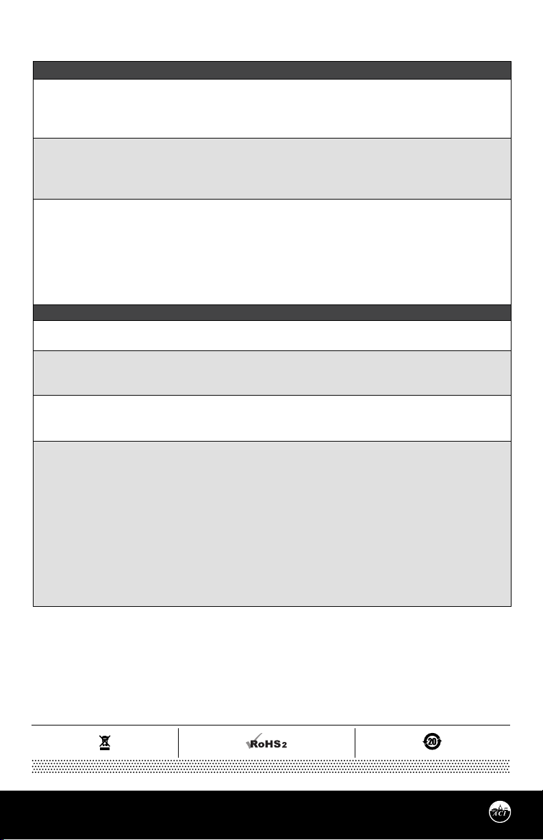
TROUBLESHOOTING
HUMIDITY READING PROBLEM
No Reading
• Check that you have the correct supply voltage at the power terminal blocks.
• Check that wiring configurations and all DIP switch settings are as in FIGURE 7 and 8.
• Verify that the terminal screws are all connected tightly and that all of the wires are firmly in place.
Erratic readings
• Verify that all of the wires are terminated properly.
• Make sure that there is no condensation on the board.
• Check that the input power is clean. In areas of high RF interference or noise, shielded cable may be necessary to stabilize signal.
Inaccurate readings
• Verify proper mounting location to conrm no external factors (see mounting locations above).
• Check the output (voltage or current) against a highly accurate recently calibrated secondary reference. Measue RH at
the location of the sensor using the secondary reference, then calculate the RH percentage using the RH CONVERSION
FORMULAS (p. 5). Compare the calculated output to reference.
• If the sensor is brand new, leave the sensor powered for at least 30 minutes to stabilize.
• If you suspect that the transmitter is not reading within the specied tolerance, please contact ACI for further assistance.
TEMPERATURE PROBLEM
No Reading
• No power to board - check voltage at power terminal - should be between +8.5 and 32 VDC.
Reading too Low
• RTD wires shorted. Disconnect wies from terminal block and check with ohmmeter. Reading should be close to 100 Ω or 1 KΩ.
• RTD Improper range of transmitter (too low). Check current or voltage - should be between 4-20 mA, 1-5 V, or 2-10 V.
Reading too High
• RTD opened. Disconnect sensor wires from terminal block and check with ohmmeter. Reading should be close to 100 Ω or 1 KΩ.
• Improper range of transmitter (too high). Check current or voltage - should be between 4-20 mA, 1-5 V, or 2-10 V.
Reading is Inaccurate
• Sensor check: Disconnect sensor wires from terminal block and check with ohmmeter. Compare the resistance reading
to the Temperature vs Resistance curves located on ACI’s website.
• Transmitter check: Make sure sensor wires are connected to terminal block. Determine that the proper output is being
transmitted based on predetermined span:
1. Go to ACI Website, Span to Output Page: http://www.workaci.com/content/span-output
2. Enter the low end of the span
3. Enter the high end of the span
4. Click on the output of the transmitter. This will generate a span to output chart.
5. Measure output of transmitter.
6. Compare measured output to calculated output
Automation Components, Inc.
2305 Pleasant View Road | Middleton, WI 53562
Phone: 1-888-967-5224 | Website: workaci.com
Page 7
Version: 7.0
I0000829
Page 8
Automation Components, Inc.
2305 Pleasant View Road
Middleton, WI 53562
Phone: 1-888-967-5224
Website: workaci.com
Page 8
Automation Components, Inc.
2305 Pleasant View Road | Middleton, WI 53562
Phone: 1-888-967-5224 | Website: workaci.com
Version: 7.0
I0000829
 Loading...