

Page 1
MADE IN
User’s Guide
Shop online at
omega.com
e-mail: [email protected]
®
For latest product manuals:
omegamanual.info
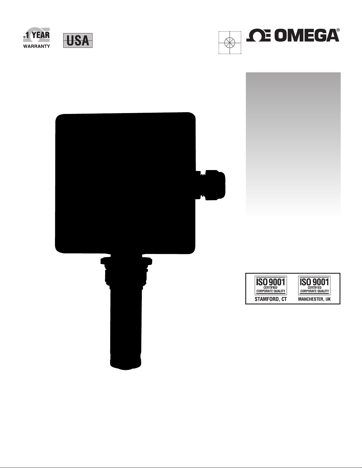
RHCM-40 SERIES
Dew Point Transmitter with a
Humidity Option Configuration
Page 2

OMEGAnet®Online Service Internet e-mail
omega.com [email protected]
Servicing North America:
U.S.A.: Omega Engineering, Inc., One Omega Drive, P.O. Box 4047
ISO 9001 Certified Stamford, CT 06907-0047 USA
Canada: 976 Bergar
Laval (Quebec), H7L 5A1, Canada
Toll-Free: 1-800-826-6342 TEL: (514) 856-6928
FAX: (514) 856-6886 e-mail: [email protected]
For immediate technical or application assistance:
U.S.A. and Canada: Sales Service: 1-800-826-6342/1-800-TC-OMEGA
Customer Service: 1-800-622-2378/1-800-622-BEST
Engineering Service: 1-800-872-9436/1-800-USA-WHEN
®
®
®
Servicing Asia:
China:: 1698 Yi Shan Road, Unit 102
Min Hang District
Shanghai, China 201103 P.R.C.
Hotline: 800 819 0559/400 619 0559
e-mail: [email protected]
Servicing Europe:
Benelux: Toll-Free: 0800 099 3344 TEL: +31 20 347 21 21
FAX: +31 20 643 46 43 e-mail: [email protected]
Czech Republic: Frystatska 184
733 01 Karviná, Czech Republic
TEL: +420-59-6311899 FAX: +420-59-6311114
e-mail: [email protected]
France: Toll-Free: 0805 541 038 TEL: 01 57 32 48 17
FAX: 01 57 32 48 18 e-mail: [email protected]
Germany/ Austria: Daimlerstrasse 26
D-75392 Deckenpfronn, Germany
Toll-Free: 0800 8266342 TEL: +49 (0) 7056 9398-0
FAX: +49 (0) 7056 9398-29 e-mail: [email protected]
United Kingdom: OMEGA Engineering Ltd.
ISO 9001 Certified One Omega Drive, River Bend Technology Centre, Northbank
Irlam, Manchester M44 5BD United Kingdom
Toll-Free: 0800-488-488 TEL: +44 (0) 161 777-6611
FAX: +44 (0) 161 777-6622 e-mail: [email protected]
It is the policy of OMEGA Engineering, Inc. to comply with all worldwide safety and EMC/EMI
regulations that apply. OMEGA is constantly pursuing certification of its products to the European New
Approach Directives. OMEGA will add the CE mark to every appropriate device upon certification.
The information contained in this document is believed to be correct, but OMEGA accepts no liability for any
errors it contains, and reserves the right to alter specifications without notice.
WARNING: These products are not designed for use in, and should not be used for, human applications.
Page 3

RHCM-40 Series
Dew Point Transmitter with a Humidity
Option Configuration
OPERATORS MANUAL
1
Page 4

RHCM-40
TERMINAL
ITEM
1,2
SERVOLOCK SIGNAL
OR ALARM 2
3,4
CLEAN MIRROR
SIGNAL OR ALARM 1
5
CHASSIS GROUND
6
ANALOG OUTPUT 2
7
ANALOG OUTPUT 1
8
ANALOG OUTPUT RET.
9
FOR FACTORY USE
10
FOR FACTORY USE
11
RS232 RETURN
12
DC POWER IN (+)
13
DC POWER IN (-)
14
RS232 TX
15
RS232 RX
QUICK STARTUP GUIDE
STARTUP
1. Mount the RHCM-40 in position to measure the desired gas.
2. Connect wiring to the main terminal strip as shown below:
Note: Connect DC POWER IN and only the Outputs desired.
See the Manual for details.
3. Turn on the DC power supply. Specifications are: 24VDC ± 20%,
1A maximum.
4. After the self-test procedure, start recording valid data.
2
Page 5

TABLE OF CONTENTS Page
1.0 Quick Startup Guide 2
2.0 Introduction 6
2.1 General Description 6
2.2 Standard Factory Configurations 7
2.2.1 Factory Default Output Ranges 9
2.3 Options and Accessories 9
3.0 Installation 10
3.1 Placement of Instrument 10
3.2 Mounting 10
3.2.1 Wall Mount 10
3.2.2 Duct Mount 10
3.2.3 Remote Mount 10
3.2.4 Pipe Mount 11
3.3 Electrical Wiring 11
3.3.1 Power Supply 11
3.3.2 Input/Output Wiring 13
3.4 Selection of Analog Outputs 14
4.0 Operation 15
4.1 Placement of Instrument 15
4.2 Flow Control 15
4.3 Clean Mirror Signal 15
4.4 Using the RS-232 Serial Port 16
4.4.1 Serial Port Setup 16
4.4.2 Programming via the Serial Port 17
4.4.3 Changing the Digital Display 17
4.4.4 Relay Outputs 19
4.4.4.1 Configuring Relays as Alarms 20
4.4.5 Calibrating the Analog Outputs 21
4.4.6 Programming the Serial Output 22
4.4.7 Auto Validation Cycle 23
5.0 Maintenance 24
5.1 Routine Maintenance 24
5.1.1 Mirror Cleaning Schedule 24
5.1.2 Cleaning the Mirror 24
3
Page 6

6.0 Specifications 26
7.0 Appendix 27
7.1 NIST Traceability 28
7.2 Mounting Dimensions 29
7.2.1 Wall Mount (plastic housing) 29
7.2.2 Duct Mount (metal housing) 30
4
Page 7

LIST OF ILLUSTRATIONS Page
2-1 Standard Configurations 6
3-1 Terminal Strip Wiring 13
3-2 Output Selector Switches 14
5-1 Cleaning the Mirror 25
LIST OF TABLES
3-1 Terminal Strip Wiring 12
3-2 Analog Output Switch Settings 14
4-1 Serial Cable Wiring 16
5
Page 8
2.0 INTRODUCTION
2.1 GENERAL DESCRIPTION
The RHCM-40 Dew Point/Humidity Transmitter is an optical chilled mirror
hygrometer, designed to continuously measure the moisture content in gases.
With an option to acquire an air temperature probe, this transmitter can than
display dew point, humidity and temperature and have a signal out for two of the
following three parameters, dew point, humidity or temperature The instrument is
powered by 24VDC. It uses the chilled mirror dew point temperature
condensation principle to determine the water vapor concentration in gas
mixtures, and a platinum resistance thermometer to accurately measure that
temperature. This principle is fully explained in the Appendix to this manual.
Outputs include 4 to 20 mA (Factory default unless specified otherwise when
ordering), 0 to 5VDC, or 0 to 10VDC, field-selectable. Two sets of analog
outputs are supplied, unless Dew Point only is ordered. Additional outputs
include an RS-232C serial port, as well as electrically isolated relay contacts.
Various housings are available for the RHCM-40. These include a plastic (IP65)
dust-tight and water resistant package, as well as an aluminum housing with
conduit fittings. Many options and accessories are available, and these are
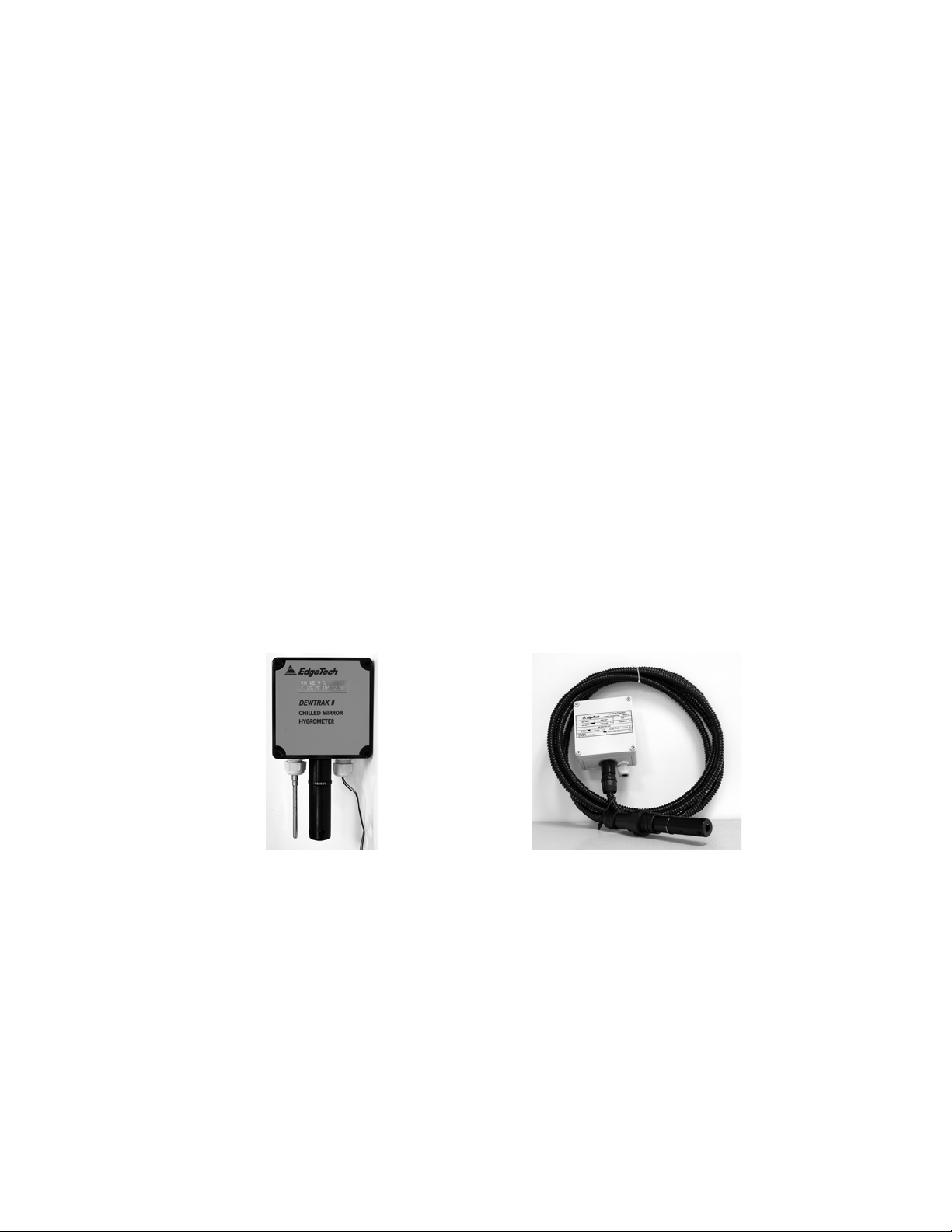
described below. Figure 2-1 shows a few of the available models.
Figure 2-1 Standard RHCM-40 Configurations
Wall Mount Remote Mount
6
Page 9
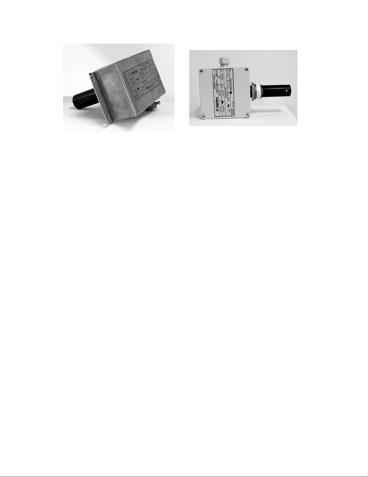
Duct Mount Pipe Mount
2.2 STANDARD FACTORY CONFIGURATIONS
The RHCM-40 is designed with a large number of standard configurations for
user convenience, as shown here. In addition, you can consult the Factory for
special configurations if needed.
RHCM-40-PL- W A wall-mount configured Dew Point/Humidity transmitter***
with a plastic enclosure, a two-stage chilled mirror sensor, two programmable
analog outputs, an RS-232 bi-directional serial port, and alarm relays.
RHCM-40-A L- W A wall-mount configured Dew Point/Humidity transmitter***
with an aluminum enclosure, a two-stage chilled mirror sensor, two
programmable analog outputs, an RS-232 bi-directional serial port, and alarm
relays.
RHCM-40-PL- D A duct-mount configured Dew Point/Humidity transmitter***
with a plastic enclosure, a two-stage chilled mirror sensor, two programmable
analog outputs, an RS-232 bi-directional serial port, duct mount flange kit, and
alarm relays.
RHCM-40-AL- D A duct-mount configured Dew Point/Humidity transmitter***
with an aluminum enclosure, a two-stage chilled mirror sensor, two
programmable analog outputs, an RS-232 bi-directional serial port, duct mount
flange kit, and alarm relays.
RHCM-40-P L- R A remote-mount configured Dew Point/Humidity
transmitter*** with a plastic enclosure, a two-stage chilled mirror sensor, two
programmable analog outputs, an RS-232 bi-directional serial port, duct mount
flange kit, 6 foot cable between sensor and electronics, and alarm relays.
RHCM-40-A L- R A remote-mount configured Dew Point/Humidity
transmitter*** with an aluminum enclosure, a two-stage chilled mirror sensor, two
programmable analog outputs, an RS-232 bi-directional serial port, duct mount
flange kit, 6 foot cable between sensor and electronics, and alarm relays.
7
Page 10

RHCM-40-P L- P A pipe-mount configured Dew Point/Humidity transmitter***
with an plastic enclosure, a two-stage chilled mirror sensor, two programmable
analog outputs, an RS-232 bi-directional serial port, 1-1/4 inch NPT brass pipe
mount fitting, and alarm relays.
RHCM-40-A L- P A pipe-mount configured Dew Point/Humidity transmitter***
with an aluminum enclosure, a two-stage chilled mirror sensor, two
programmable analog outputs, an RS-232 bi-directional serial port, 1-1/4 inch
NPT brass pipe mount fitting, and alarm relays.
**** this transmitter is typically a dew point transmitter and can only be
configured as a humidity transmitter when the air temperature probe option is
purchased
8
Page 11

2.2.1 FACTORY DEFAULT OUTPUT RANGES
These standard output measurement ranges apply to all instruments unless
specified otherwise when ordering. They correspond to 4 to 20 mA. See 2.1
above for other field-selectable electrical ranges.
• Dew Point Only Dew Point: -40°C to 60°C
• Dew Point/Air Temp. Dew Point: -40°C to 60°C
Air Temp: -40°C to 60°C
% RH 0 to 100%
2.3 OPTIONS AND ACCESSORIES
The RHCM-40 is designed to accept a number of options and accessories to
expand its capabilities.
ATDT-W Add a platinum RTD Air Temperature probe to the wall-mount
package. (Used with either the plastic or aluminum housing.)
ATDT-R Add a remote-mount platinum RTD Air Temperature probe. A 10
foot cable is standard. (Used with either the plastic or aluminum
housing.)
ATDT-I Add an integrated air temperature platinum RTD sensor embedded
in the dew point sensor.
RTD Resistive (100 ohm platinum RTD) Dew Point output
ACDT A universal power supply for the RHCM-40, for AC sources of 85 to
230 VAC, 50/60 Hz.
ECDT Add additional sensor cable length for either the dew point or the air
temperature sensor, up to 50 feet in length.
AR Aspirator kit
RD Add a digital LCD display to the plastic-housed RHCM-40.
SC1 A sample chamber for flow-through humidity measurements
SC A low pressure sample chamber with fittings
9
Page 12

3.0 INSTALLATION
3.1 PLACEMENT OF INSTRUMENT
If possible, locate the RHCM-40 dewpoint/humidity Transmitter in a clean area
where the air to be measured is allowed to freely move around the enclosure.
Optimal performance of the instrument is experienced when air is gently moving
over the chilled mirror sensor, providing a representative sample for
measurement. If you have purchased an instrument with the optional digital
display, choose a location where the display may be conveniently observed.
Depending on the location selected, it may be convenient to wire the instrument
prior to mounting.
3.2 MOUNTING
3.2.1 WALL MOUNT
Instruments with the plastic wall mount housing are mounted to a flat surface as
follows:
1. Remove the front cover. Using a flat screwdriver, carefully unscrew the
four slotted plastic screws.
2. Mounting screws (not provided) are inserted in the same holes as the
cover screws. They must have a head diameter that is small enough
to fit inside the clearance holes, but large enough to press against the
collar located at the bottom of the holes. No. 8 pan head or round
head screws are recommended.
3. Reinstall the front cover. Do not over-tighten the cover mounting
screws.
3.2.2 DUCT MOUNT
The duct mount unit is available with a metal housing and metal conduit fittings,
and has a built-in mounting flange. Use No. 6 screws to mount the flange
securely to the duct.
It is also available with a plastic (IP65) housing. In this case, a separate duct
mount flange kit is provided.
3.2.3 REMOTE MOUNT
A 6 foot (1.8 meter) remote sensor cable is provided between the sensor and the
instrument housing. Consult the factory for other lengths. A remote mount unit is
available with either a plastic or metal housing. Mount the housing as described
above. If a duct mount flange kit is provided, mount it to the duct in a location
close to the electronics housing.
10
Page 13

3.2.4 PIPE MOUNT
The pipe mount configurations are available with either a plastic or metal
electronics housing. They include a 1-¼ inch NPT brass pipe mount fitting. A
corresponding female mating fitting, user-supplied, should be mounted in a gastight manner to a flat surface of a duct, pipe, or chamber wall containing the gas
to be measured. Clean all surfaces of the pipe mount of oil, grease, and
contaminants.
To install the mount and sensor:
Screw the front portion of the mounting sleeve (the tapered NPT fitting)
into the pre-mounted user-supplied mating fitting. Teflon™ tape or pipe
thread sealant may be used for a good seal. Do not over-tighten.
If the Type SC1 sample chamber is to be used, simply screw it down to any flat
surface, and connect ¼ inch OD tubing to the inlet and outlet compression
fittings. Tubing should be reasonably non-hygroscopic, such as copper,
Teflon™, or Tygon™. Do not use PVC tubing. See the above instructions for
probe mounting.
3.3 ELECTRICAL WIRING
3.3.1 POWER SUPPLY
You will need a power supply voltage of 24VDV +/- 20% at 1A for each DewTrak
ll that you are installing. Stranded wire, 18 gauge minimum, color coded, should
be used. Route the wires through the feed-through bushing on the body of the
unit, and connect them to Terminal Strip TB1 as shown in Table 3-1 and Figure
3-1 below.
11
Page 14

TERMINAL
ITEM
1,2
SERVOLOCK SIGNAL
OR ALARM 2
3,4
CLEAN MIRROR
SIGNAL OR ALARM 1
5
CHASSIS GROUND
6
ANALOG OUTPUT 2
7
ANALOG OUTPUT 1
8
ANALOG OUTPUT RET.
9
FOR FACTORY USE
10
FOR FACTORY USE
11
RS232 RETURN
12
DC POWER IN (+)
13
DC POWER IN (-)
14
RS232 TX
15
RS232 RX
CAUTION: BE SURE TO OBSERVE CORRECT WIRING POLARITY.
DO NOT APPLY POWER TO THE UNIT UNTIL THE
INSTALLATION HAS BEEN COMPLETED.
Table 3-1 Terminal Strip Wiring
12
Page 15
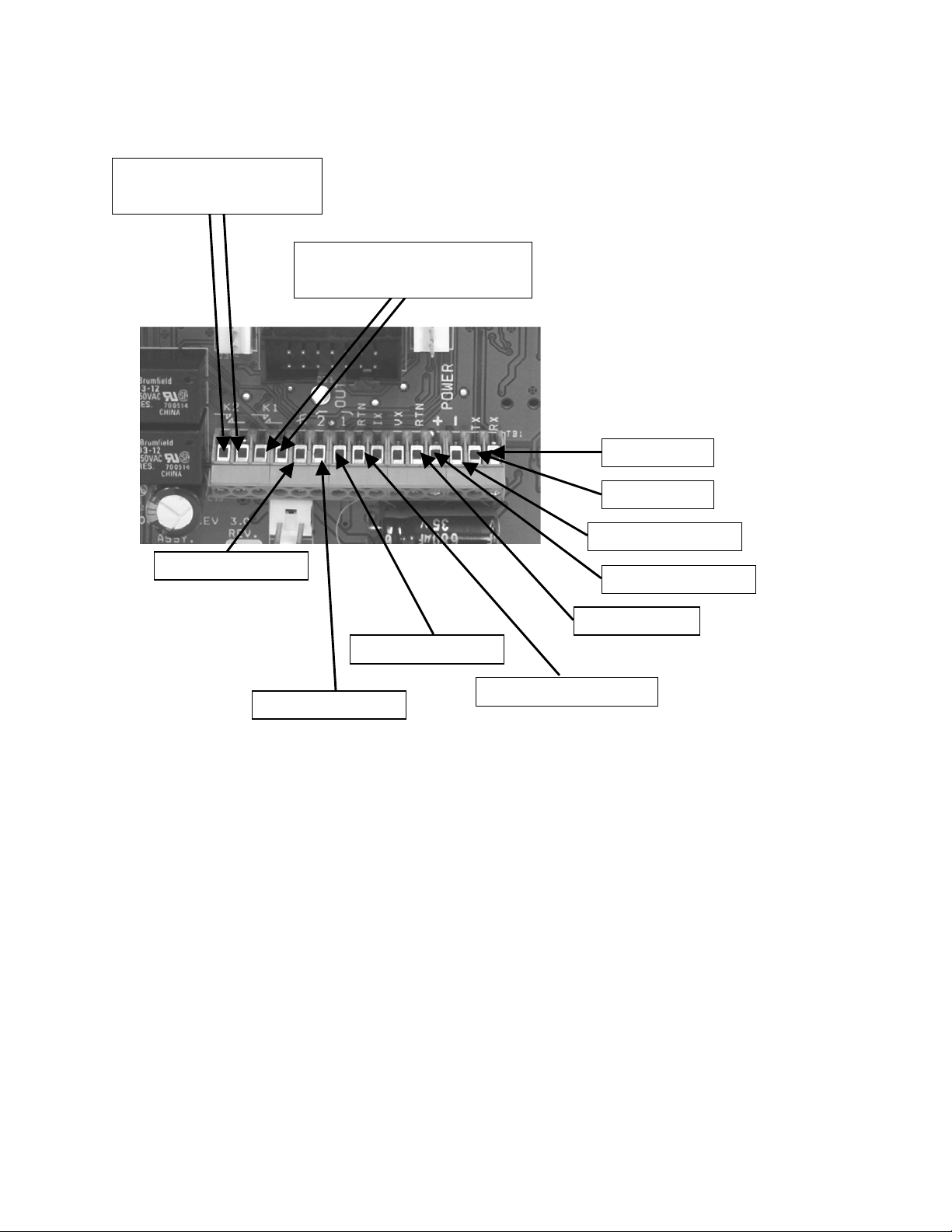
Figure 3-1 Terminal Strip Wiring
DC PWR IN
ANALOG OUT
ANALOG OUT
RS232
CLEAN MIRROR
SIGNAL
SERVOLOCK
SIGNAL
CHASSIS
3.3.2 INPUT/OUTPUT WIRING
Wire the Analog Outputs as required. See 3.4 below for information on output
selection.
Connect the RS-232 Serial Output if desired. Only 2 wires are required if the
output is needed for transmitting information only. A third wire is added for bidirectional communications with the serial port.
Connect the relays as needed. Note that they may be programmed to provide
either a Clean Mirror signal and a ServoLock signal, or they may be used as
upper or lower setpoint Alarm Relays. See Section 4.4.4 for further information.
13
Page 16
3.4 S ELECTION OF ANALOG OUTPUTS
OUTPUTS
SWITCH 1
SWITCH 2
4 to 20 mA
DOWN
----
0 to 5VDC
UP
UP
0 to 10VDC
UP
DOWN
SWITCH 1
SWITCH 2
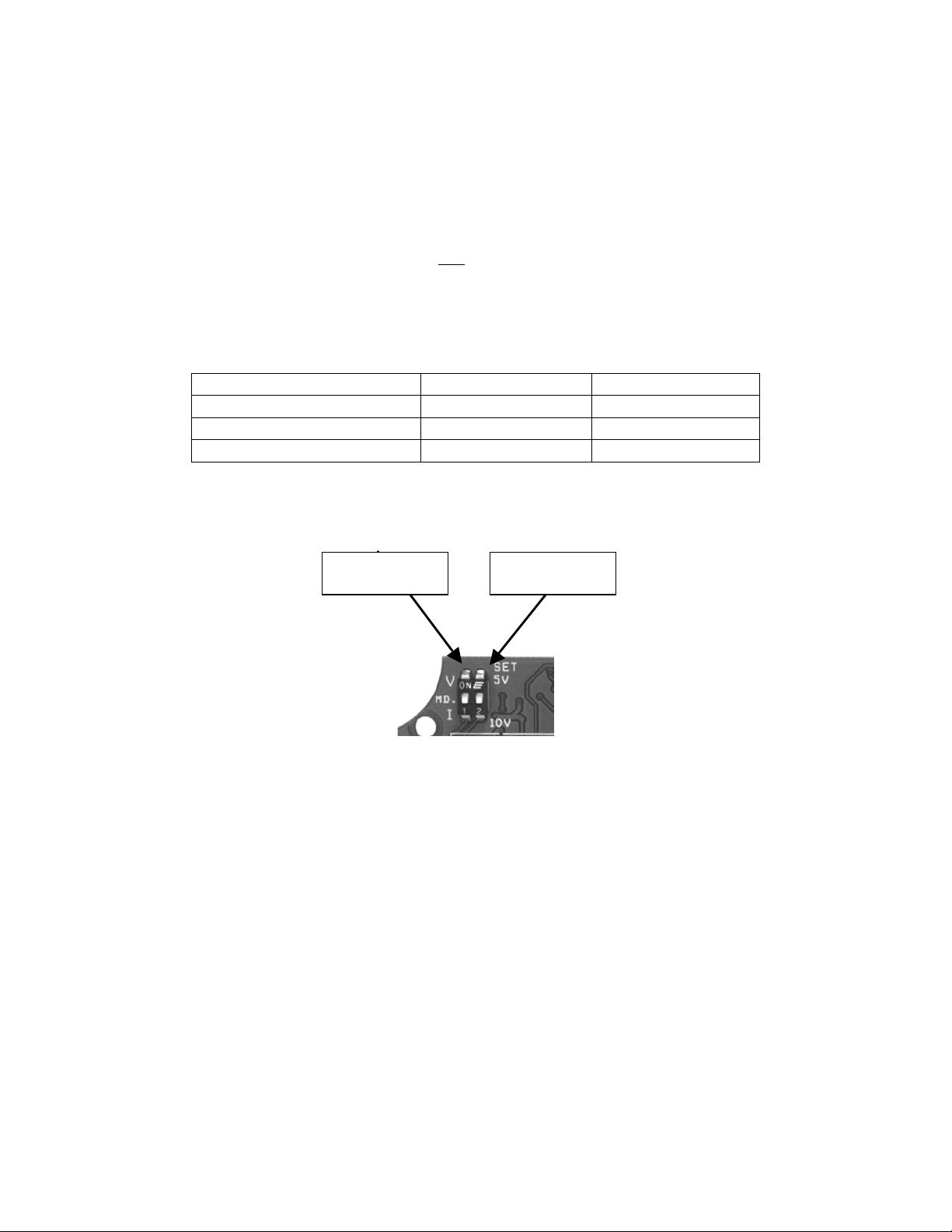
Two small electrical switches allow the selection of analog output scaling. These
switches are located in the top left corner of the circuit board as shown in Figure
3-2 below. You can select the outputs to be either 4 to 20 mA, o to 5VDC, or 0 to
10VDC. To modify the output scaling, proceed as follows:
1. Be sure that DC Power is not applied to the unit.
2. Remove the outer cover.
3. Using a small screwdriver, set the switches as shown in Table 3-2.
4. Replace the cover.
5. Reapply DC power.
Table 3-2. Analog Output Switch Settings
Figure 3-2 Output Selector Switches
14
Page 17

4.0 OPERATION
4.1 PLACEMENT OF INSTRUMENT
If possible, locate the RHCM-40 Humidity Transmitter in a clean area where the air to
be measured is allowed to freely move around the enclosure. Optimal performance
of the instrument is experienced when air is gently moving over the chilled mirror
sensor, providing a representative sample for measurement.
4.2 FLOW CONTROL
The sensor probe is designed so that the flow rate can be changed. This is achieved
by means of rotating the sensor cover around the sensor probe base. By aligning
and misaligning the holes on the sensor cover with those of the sensor base, the air
flow can be controlled across the surface of the chilled mirror sensor. The proper
alignment of the holes (and thus gas flow control) depends on the application. The
RHCM-40 sensor is designed to accommodate various application conditions.
Optimal performance of the sensor may require several trial and error adjustments.
“Optimal” performance is defined by the response time of the sensor, (lower flow
results in a slower response). Accuracy is unaffected by the flow.
Flow control can also be achieved by constructing a simple external sampling system.
You can use an Omega Engineering Sample Chamber, Model SC1, along with a
flowmeter which can adjust the flow between 0 to 5 SCFH. Contact the factory for
more details.
4.3 CLEAN MIRROR SIGNAL
The RHCM-40 Humidity Transmitter features an electro-optical technique to detect
and maintain the dew layer on the mirror surface. By use of the Auto Validation
Cycle, the system will indicate when the mirror needs attention. In the factory default
configuration, the Clean Mirror alarm relay actuates when the mirror requires periodic
cleaning. An indication also appears on the RS-232 serial output. When the Clean
Mirror alarm actuates, the instrument is still operational and the accuracy of the
measurement is not affected by the presence of contaminants on the mirror surface.
Note: This alarm requires that the mirror be cleaned within a reasonable period of
time, or the specified accuracy can no longer be guaranteed.
There are many variables determining the frequency that your transmitters require
maintenance. These include flow rate and the amount of particulate matter in the gas
being measured. Once you determine the typical contamination rate in your unique
application, it is recommended that you initiate a periodic maintenance schedule.
This minimizes the chance of obtaining incorrect data due to mirror contamination.
15
Page 18

4.4 USING THE RS-232C SERIAL PORT TO
DB-9 SERIAL
CONNECTOR
TB1 TERMINAL STRIP
Pin 2
TX – Term. 14
Pin 3
RX – Term 15
Pin 5
RTN – Term. 11
REPROGRAM YOUR SETTINGS
Note: If the Factory Default settings are satisfactory, there is no reason to
perform any programming.
The RHCM-40 is very versatile. Through the Serial Port, the user has complete
control over the display units, the electrical outputs, and other features as well.
Here are some of the parameters you can select and change:
• Displayed Values (if the optional display has been supplied)
• Output Units
• Output Ranges
• Alarm Scaling (if alarms have been selected)
• RS-232 Settings (Elapsed Time Stamp, Update Rate)
• Auto Validation (On or Off)
4.4.1 SERIAL PORT SETUP
You will need a serial cable with a standard DB-9 connector on one end, which
will plug into the standard serial port connector on the back of your computer.
The other end will have three stripped wires, which will connect to Terminal Strip
TB1 on the RHCM-40 circuit board as shown below:
Table 4-1 Serial Cable Wiring
Using a terminal emulation program, such as HyperTerminal, set your PC Com
Port to:
BAUD: 19200
BITS 8
STOP BITS 1
PARITY NONE
FLOW CONTROL NONE
HyperTerminal has a setting called Control for Terminal Emulation. Set it to
AUTODETECT.
16
Page 19
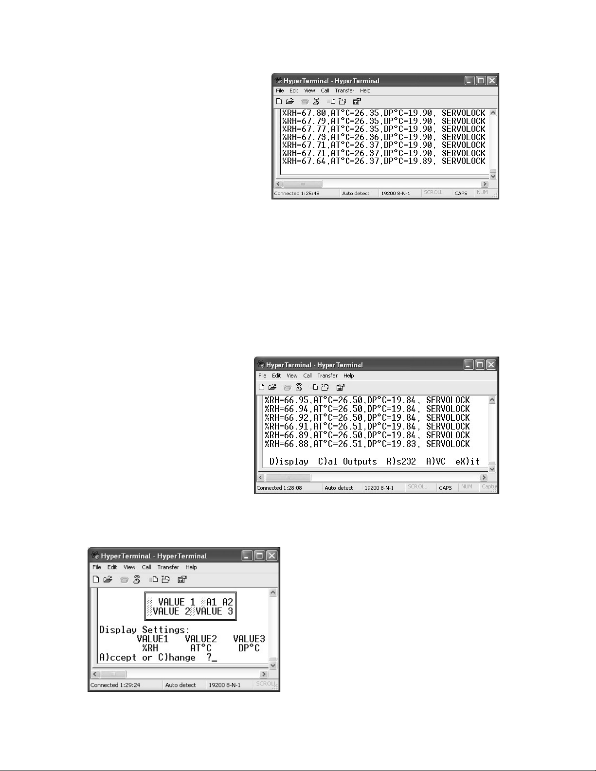
After connecting both ends of the
serial cable, apply power to the
RHCM-40. A window should be
seen, which will show some
warm-up and self test data. After
the self checking and warm-up
period, the window will display
information similar to the photo
shown here. This is the default
condition.
4.4.2 PROGRAMMING THE RHCM-40 VIA THE SERIAL
PORT
If you do not see a window similar to the one shown above, you will not be able
to program this instrument. Check your terminal emulation program, the power
supply, and check the interconnecting cable wiring as shown in Table 5 -1 above.
NOTE: WHEN PROGRAMMING ALPHABETIC CHARACTERS, USE
UPPER CASE ONLY.
To begin reprogramming,
press the ESCape key on
your computer keyboard. The
window will change to that
shown here. To select the
desired parameter, simply
select the first letter as
shown. You will find it quite
intuitive once you try it.
Several programming
examples will be shown here.
4.4.3 CHANGING THE DIGITAL DISPLAY (if you have the
Display option)
Press the D key to change the displayed
values. The window at the left will
appear. Press the A key to keep the
present values, or the C key to change
them. In this case, you will change them.
So, you will press C to change the values.
17
Page 20
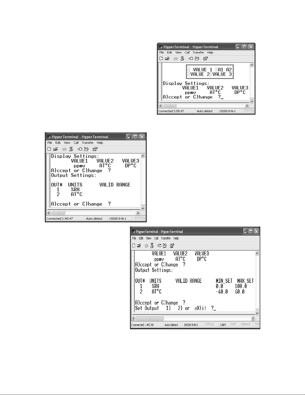
Using the Space Bar on the keyboard,
you can toggle through all the available
units to display. You will change the
first displayed parameter from %RH to
ppmv, as shown here. For VALUE1,
cycle all the available parameters using
the Space Bar until ppmv is shown.
Press Enter. Press Enter again to keep
VALUE2, and press Enter again to keep
VALUE3. Press A for A)ccept. You
have now selected your desired
displayed parameters.
The outputs shown are %RH
with a range of 0 to 100%RH,
and Air Temperature (AT)
with a range of -40 to 60°C.
These are the Factory
defaults.
The screen at the left will now be seen,
and you will have an opportunity to
select the electrical outputs and make
them represent any parameter you wish.
To do so, press C for C)hange, and the
screen shown below will appear.
18
Page 21
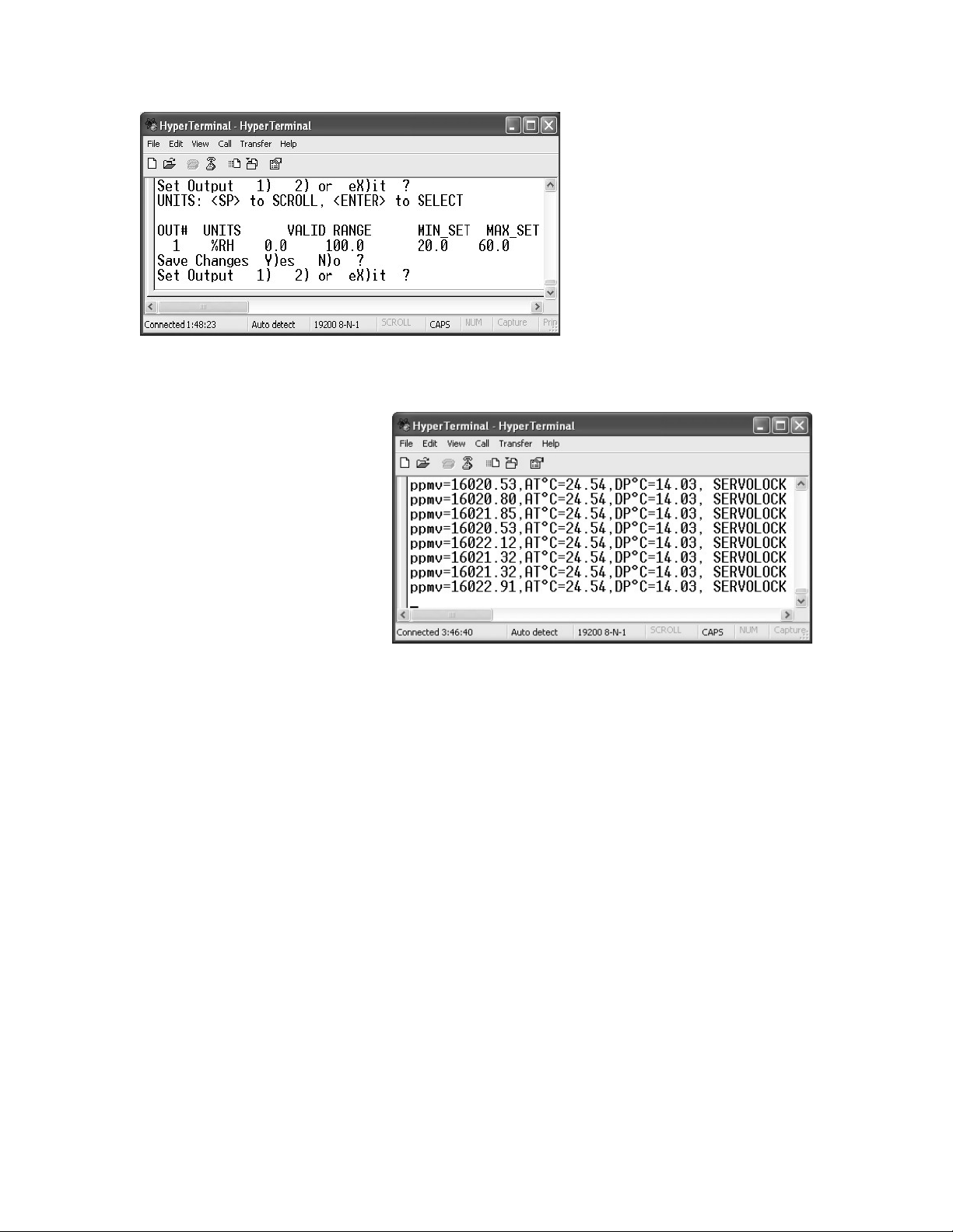
Perhaps you would like
additional resolution on the
Relative Humidity analog
output. So, for this example,
you will change the output
scaling from 0 to 100 %RH
to 20 to 60%RH. Press 1 on
the keyboard in order to
change Parameter 1. Set
the MIN SET to 20. Press
Enter. Set the MAX SET to
60. Press Enter. Press Y for Y)es to save the changes. You can then enter X
for eX)it if desired.
You will see that the default
window will reappear, and
will be constantly updated.
Comparing it with the
window shown at the
beginning of this chapter,
the first parameter has been
changed from %RH to
ppmv. A meter on the
analog output would show
that the first output is on
%RH, with scaling of 0 to 100% corresponding to 20 to 60%RH.
4.4.4 RELAY OUTPUTS
Two relays, K1 and K2, are built into the RHCM-40. The relay contacts are
brought out to the main terminal strip, TB1. The contacts are Normally Open
(NO), or Form A. As supplied from the Factory, they are configured as follows:
K1 is used as the Clean Mirror signal. When energized, it advises the user that
contamination has accumulated on the dew point sensor mirror, and the system
should be shut down for a routine cleaning. When this signal occurs, the system
still provides dew point measurements that are in specification, but the closure
indicates that readings may become unreliable if the mirror is not cleaned before
long.
K2 is the ServoLock signal. ServoLock is an Omega Engineering term indicating
that the mirror servo loop is operating properly, and there is a correct dew layer
on the mirror surface. You can use this relay signal as an indication that good
dew point data is being supplied by the RHCM-40. Or conversely, the lack of this
signal may be used as a “busy” signal, telling the user to disregard the data being
received at this time.
19
Page 22
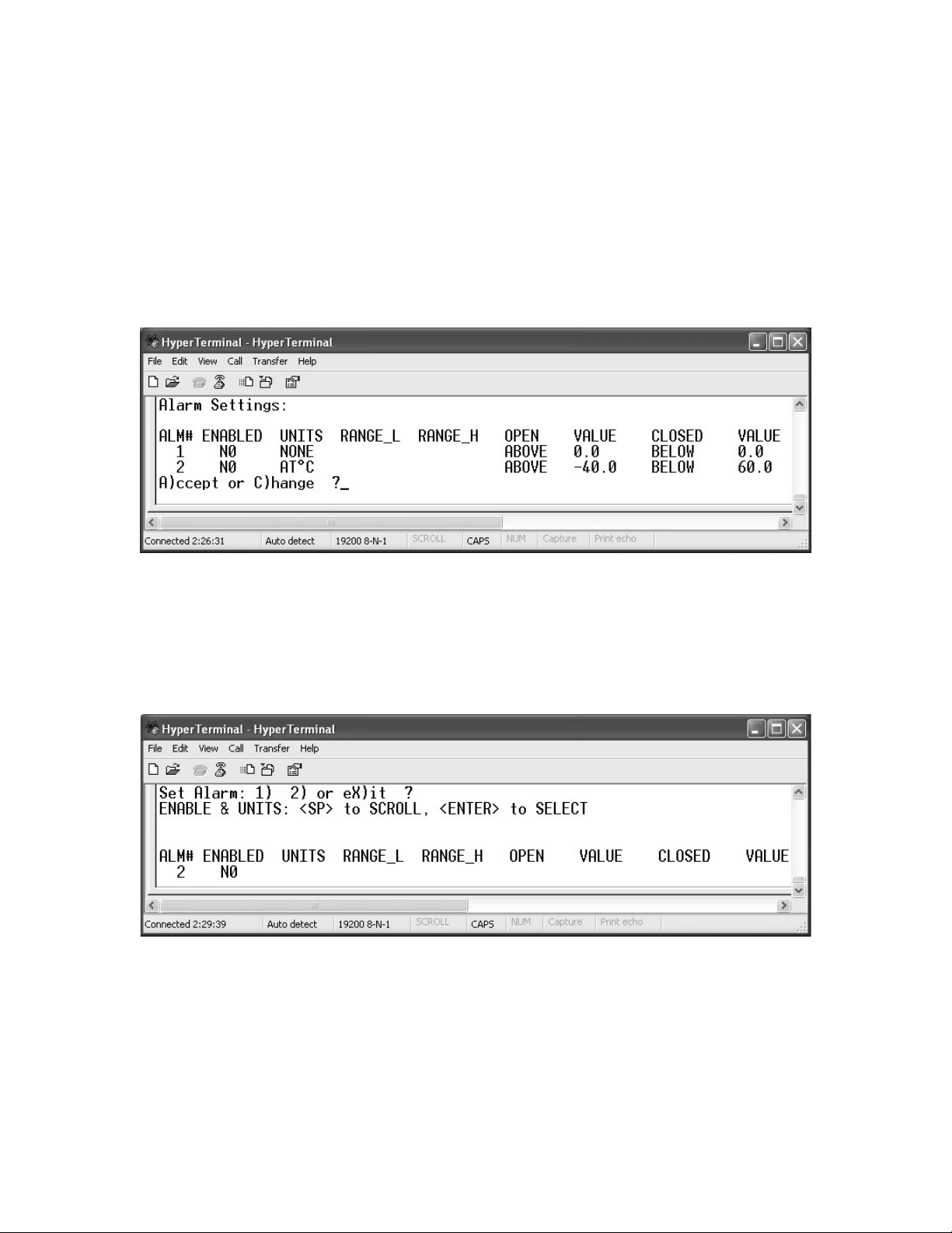
4.4.4.1 CONFIGURING THE RELAYS AS ALARMS
Using the RS-232 Port, relays K1 and K2 may be set as Alarm Relays. You can
program them to actuate on any increasing or decreasing measured or
calculated humidity parameter.
NOTE: IT IS ADVISABLE TO PROGRAM IN A SMALL OVERLAP OF
THE “ON” VALUE AND THE “OFF” VALUE, SO THAT THE RELAY
DOES NOT CHATTER WHEN THE MEASURED VALUE IS EXACTLY
AT THE SETPOINT. THIS OVERLAP IS CALLED “HYSTERESIS.”
You can press D for D)isplay until the above picture appears. If you do not wish
to use the Alarm Relays, A for A)ccept, then X to eX)it.
To program the relays as Alarms, proceed as follows: Press C for C)hange when
the above picture appears. You will then be able to program Alarm1 and Alarm2
as shown in the picture below.
In this case, enable Alarm2 by scrolling with the space bar and selecting YES.
See the picture shown below.
20
Page 23
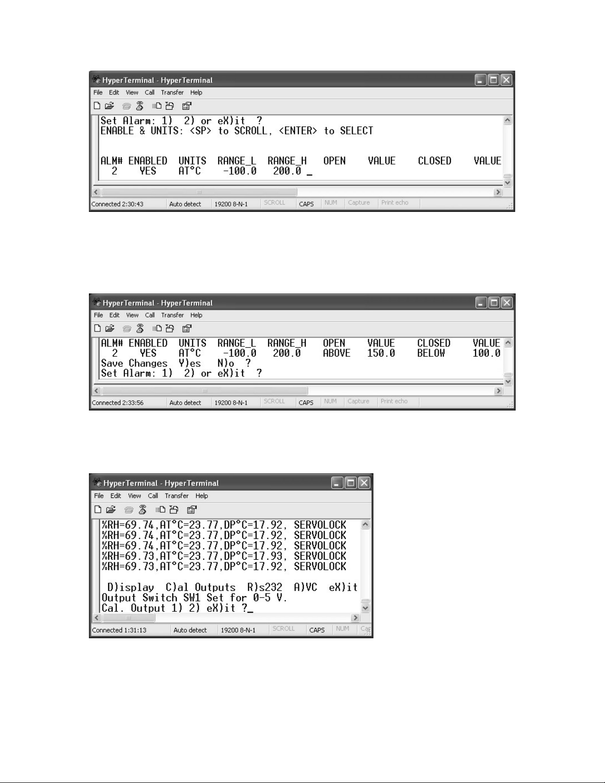
You will then be able to select the values for the OPEN and CLOSED conditions.
In this case, you would like Alarm2 to OPEN at an Air Temperature reading of
150, and to remain open above that value. You would like the relay to CLOSE at
a reading of 100, and to remain closed below that value. You can then save the
changes, and then proceed to program Alarm1 or press X for eX)it.
4.4.5 C ALIBRATING THE ANALOG OUTPUTS
If you have a precise milliammeter or voltmeter, you can check the accuracy and
scaling of the analog
outputs. Connect your
meter to terminal strip
TB1 on the circuit board.
If you have selected 4 to
20 mA current output,
you can connect it in
series with the load. If
you have selected 5 or
10 VDC, connect it
between the voltage
output and RTN.
Press C for C)al Outputs. This window shows that the output switches on the
circuit board are set for analog outputs of 0 to 5VDC, and you can now select
Output 1 or 2 to test. Selecting Output 1, a new window will be seen, as shown
below. A new output voltage will be measured on the terminal strip,
21
Page 24
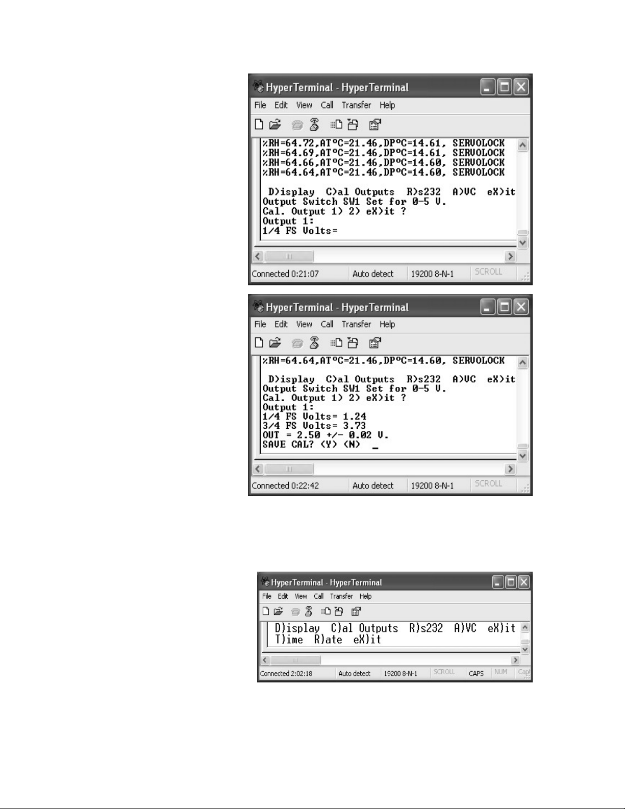
corresponding to ¼ of Full
Scale. Type in this
voltage reading as
requested by the program.
Press the Enter key. You
will then see a second
screen, giving you the
value of ¾ of Full Scale.
Also, type in this value as
requested by the program.
Press Enter. Now, the
voltage corresponding
exactly to midscale
measured at the output.
Your meter should read
2.50VDC +/- 0.02 volts, +/the meter error. You can
save the calibration, and
then eX)it from the
program.
will be
4.4.6 PROGRAMMING THE SERIAL OUTPUT
From the main (default) window, press the ESCape key. Then press R for
R)s232. You will then have
two options. You can add
an Elapsed T)ime Stamp to
the serial output, and you
can select an Update Rate.
If you select T for the output
T)ime Stamp, you will see
the window shown here.
You can now select Y for YES, or N for NO. If you select R for Update R)ate,
you will see the window shown here. It allows you to select the Serial Port
update rate in seconds, from 3 to 3600 seconds, or 1 hour maximum.
22
Page 25
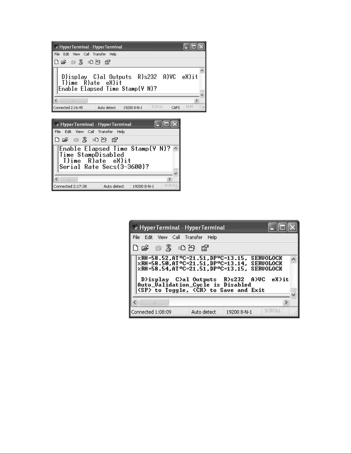
4.4.7 AUTO VALIDATION CYCLE
If desired, you can also
enable or disable the
Auto Validation cycle.
This automatic built-in
cycle is a self-test
feature. Every 6 hours,
it heats the mirror,
evaporating the dew
layer, and checks for
excessive
contamination on the
surface. If conditions
are acceptable, it
proceeds to grow a new dew layer and continues to take measurements. If
contaminants are excessive, it initiates the Clean Mirror alarm. During the
periodic cycle, the analog outputs are held for 30 seconds at the value that
existed
the Auto Validation cycle, and then Save and Exit.
just before
the cycle started. Press the Space Bar to Enable or Disable
23
Page 26

5.0 MAINTENENACE
5.1 ROUTINE MAINTENANCE
The only maintenance required by the RHCM-40 is periodic mirror cleaning. The
rate of contamination, and therefore the frequency of mirror cleaning, varies from
user to user. It depends upon flow rate of the gas being measured, the quantity
of contaminants in the gas, and how wide the sensor aperture is opened.
5.1.1 MIRROR CLEANING SCHEDULE
To maintain the optimum in accurate and reliable operation of any optical chilled
mirror system, a periodic maintenance program should be established.
Depending on the application, you may want to “schedule” mirror cleaning on a
routine basis. It is recommended that the time internal between cleaning be
determined by the performance experience of the system. In other words,
operation experience with the instrument will dictate that mirror cleaning will be
scheduled just prior to when it is necessary. Cleaning the mirror excessively is no
more useful than not cleaning the mirror when it is needed.
The buildup of contamination on the mirror surface normally occurs very slowly.
Over time, particulates and other matter present in the sample gas and not
captured by filters, build up on the mirror. The result of the buildup of
contaminants on the mirror surface is reduced dry mirror reflectivity and a change
in the optical reference point. When the contamination becomes too severe to
allow specified dew point accuracy to be maintained, a CLEAN MIRROR warning
will be generated. Normally, intervals of at least 90 days between routine mirror
cleanings can be achieved. However, if the sample contaminants are particularly
high, more frequent mirror cleanings may be required. When cleaning is required,
clean the mirror surface and optical parts, as follows:
5.1.2 CLEANING THE MIRROR
To gain access to the mirror, slide the black sensor cover up approximately an inch
to allow access to the mirror surface.
1. Shut off the 24VDC power supply, allowing the mirror to equilibrate to
room temperature, evaporating the dew layer.
2. Moisten a clean cotton swab with isopropyl alcohol. Cotton swabs and
cleaning bottle are provided in the Cleaning Kit supplied.
3. Wipe the mirror surface and the optics surface in a circular motion.
4. Dry the surface with a clean cotton swab.
24
Page 27
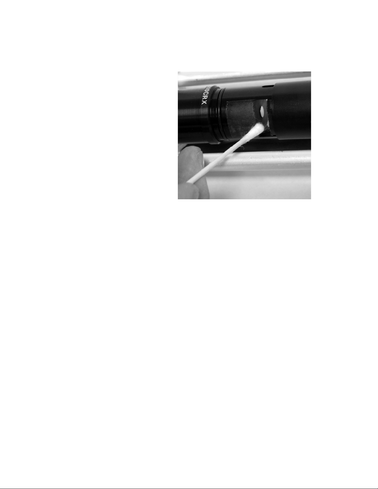
5. Next, moisten a clean swab with clean, preferably distilled water and
lightly wipe the mirror and optics areas.
6. Dry these areas thoroughly
with a clean, dry swab.
7. Slide the sensor cover
back into position. Be
sure you push it down all
the way down, past the Oring, as far as it can go.
8. Turn the power supply
back on, and wait for the
RHCM-40 to come back
into control.
Figure 5-1 Cleaning the Mirror
25
Page 28

6.0 SPECIFICATIONS
Measurement Range:
Dew Point: -40°C to 60°C (-40°F to 140°F)
Ambient Temperature: -40°C to 60°C (-40°F to 140°F)
Equivalent %RH: 1% to 95%
Depression Range: 60°C (108°F)
Accuracy: ±0.2°C (±0.36°F)
Operating Temperature:
Sensor: -40°C to 65°C (-40°F to 149°F)
Control Unit: 0°C to 50°C (32°F to 122°F)
Pressure: 100 psig maximum (Higher pressures available
on special order)
Flow Rate: Static to 3,000 linear ft/min.
Analog Outputs: 4 to 20 mA/0 to 5VDC/0 to 10VDC (selectable)
Load: 4 to 20 mA : 400 ohms or lower
0 to 5/10VDC: 1K ohm or higher
Standard Output Ranges: Dew Point: -40°F to 140°F (-40°C to 60°C)
(Programmable) Temperature: -40°F to 140°F (-40°C to 60°C)
Percent RH: 0 to 100%
Serial Outputs: RS-232C, bidirectional
Relay Outputs:
K1: Clean Mirror/Alarm 1
K2: ServoLock/Alarm 2
Contact Rating: Normally Open (Form A)
3A at 250VAC, or 30VDC
Remote Cables:
Dew Point: 6 ft. standard, 50 ft. maximum
Air Temperature: 10 ft. standard, 50 ft. maximum
Power Supply: 24VDC ±20%, 1A maximum
26
Page 29

7.0 APPENDIX
7.1 NIST Traceability
7.2 Overall and Mounting Dimensions
7.2.1 Wall Mounting Dimensions
7.2.2 Duct Mounting Dimensions
27
Page 30

7.1 N.I.S.T. TRACEABILITY – WHAT DOES IT
MEAN?
This precision measuring instrument is certified by Omega Engineering to be
traceable to N.I.S.T., the National Institute of Standards and Technology
(formerly known as the National Bureau of Standards, or NBS), in Gaithersburg,
Maryland, U.S.A. You have received a Certificate of Calibration with this
instrument. What does N.I.S.T. Traceability mean in terms of this instrument?
The instrument measures Dew Point using the Optical Chilled Mirror (OCM)
technique, which provides a primary rather then a secondary measurement of
Dew Point temperature. In addition, Dew Point is a fundamental measurement of
humidity. It is not affected by temperature.
The Dew Point temperature is measured using a Platinum Resistance
Thermometer (PRT). This device is a coil of nearly pure platinum, where the rate
of change of resistance with temperature is precisely known. Resistance is
accurately measured and is automatically converted to temperature information
within the instrument.
TRACEABILITY:
• 1. The precise platinum resistance thermometer is N.I.S.T. traceable
by the traceable resistance standards maintained by the PRT
manufacturer.
• 2. A multi-point Dew Point calibration is performed on every chilled
mirror sensor, using Omega’s traceable secondary dew point standard.
This instrument, a precise chilled mirror hygrometer, is periodically
sent directly to N.I.S.T. for certification against the USA’s Dew Point
transfer standard, a Two-Pressure Generator.
28
Page 31
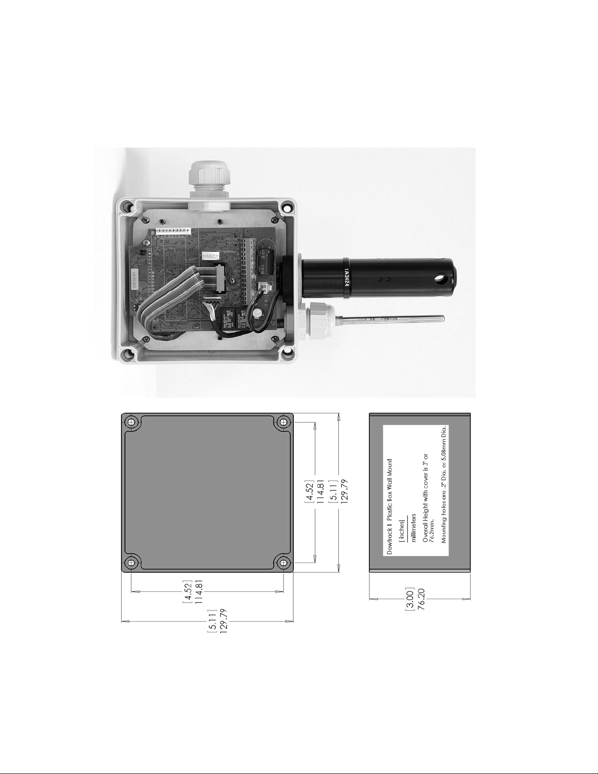
7.2 OVERALL AND MOUNTING DIMENSIONS
7.2.1 WALL MOUNT DIMENSIONS
29
Page 32
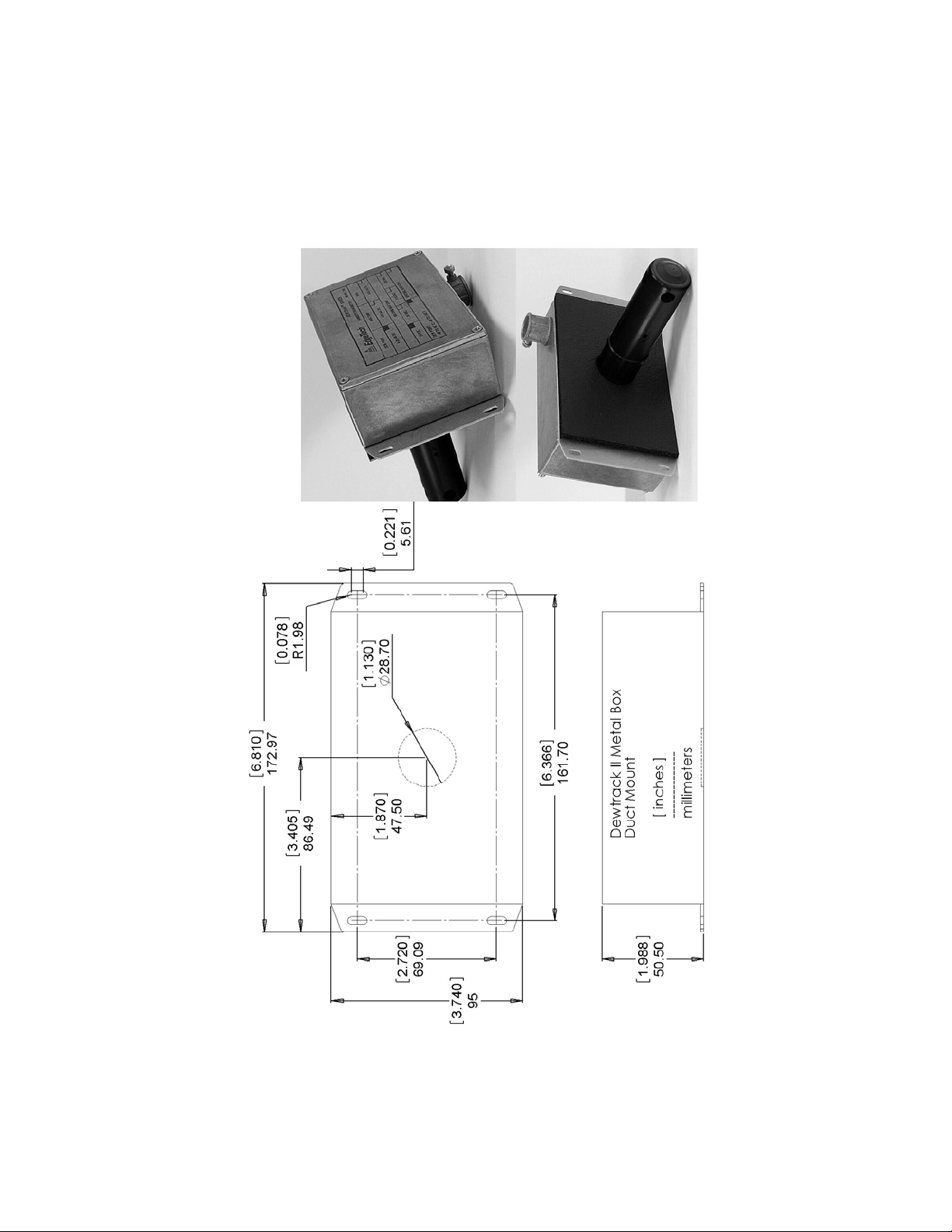
7.2.2 DUCT MOUNT DIMENSIONS
30
Page 33

Notes
31
Page 34

N o tes
32
Page 35

WARRANTY/DISCLAIMER
OMEGA ENGINEERING, INC. warrants this unit to be free of defects in materials and workmanship for a
period of 13 months from date of purchase. OMEGA’s WARRANTY adds an additional one (1) month
grace period to the normal one (1) year product warranty to cover handling and shipping time. This
ensures that OMEGA’s customers receive maximum coverage on each product.
If the unit malfunctions, it must be returned to the factory for evaluation. OMEGA’s Customer Service
Department will issue an Authorized Return (AR) number immediately upon phone or written request.
Upon examination by OMEGA, if the unit is found to be defective, it will be repaired or replaced at no
charge. OMEGA’s WARRANTY does not apply to defects resulting from any action of the purchaser,
including but not limited to mishandling, improper interfacing, operation outside of design limits,
improper repair, or unauthorized modification. This WARRANTY is VOID if the unit shows evidence of
having been tampered with or shows evidence of having been damaged as a result of excessive corrosion;
or current, heat, moisture or vibration; improper specification; misapplication; misuse or other operating
conditions outside of OMEGA’s control. Components in which wear is not warranted, include but are not
limited to contact points, fuses, and triacs.
OMEGA is pleased to offer suggestions on the use of its various products. However,
OMEGA neither assumes responsibility for any omissions or errors nor assumes liability for any
damages that result from the use of its products in accordance with information provided by
OMEGA, either verbal or written. OMEGA warrants only that the parts manufactured by the
company will be as specified and free of defects. OMEGA MAKES NO OTHER WARRANTIES OR
REPRESENTATIONS OF ANY KIND WHATSOEVER, EXPRESSED OR IMPLIED, EXCEPT THAT OF
TITLE, AND ALL IMPLIED WARRANTIES INCLUDING ANY WARRANTY OF MERCHANTABILITY
AND FITNESS FOR A PARTICULAR PURPOSE ARE HEREBY DISCLAIMED. LIMITATION OF
LIABILITY: The remedies of purchaser set forth herein are exclusive, and the total liability of
OMEGA with respect to this order, whether based on contract, warranty, negligence,
indemnification, strict liability or otherwise, shall not exceed the purchase price of the
co mponent upon which liability is based. In no even t shall OMEGA be liable for
consequential, incidental or special damages.
CONDITIONS: Equipment sold by OMEGA is not intended to be used, nor shall it be used: (1) as a “Basic
Component” under 10 CFR 21 (NRC), used in or with any nuclear installation or activity; or (2) in medical
applications or used on humans. Should any Product(s) be used in or with any nuclear installation or
activity, medical application, used on humans, or misused in any way, OMEGA assumes no responsibility
as set forth in our basic WARRANTY/DISCLAIMER language, and, additionally, purchaser will indemnify
OMEGA and hold OMEGA harmless from any liability or damage whatsoever arising out of the use of the
Product(s) in such a manner.
RETURN REQUESTS/INQUIRIES
Direct all warranty and repair requests/inquiries to the OMEGA Customer Service Department. BEFORE
RETURNING ANY PRODUCT(S) TO OMEGA, PURCHASER MUST OBTAIN AN AUTHORIZED RETURN
(AR) N UMBE R FRO M OMEG A’ S CUS T OMER SERVIC E DEPA RT M ENT ( I N OR D ER TO AVOID
PROCESSING DELAYS). The assigned AR number should then be marked on the outside of the return
package and on any correspondence.
The purchaser is responsible for shipping charges, freight, insurance and proper packaging to prevent
breakage in transit.
FOR WARRANTY
following information available BEFORE
contacting OMEGA:
1. Purchase Order number under which the product
was PURCHASED,
2. Model and serial number of the product under
warranty, and
3. Repair instructions and/or specific problems
relative to the product.
OMEGA’s policy is to make running changes, not model changes, whenever an improvement is possible. This affords
our customers the latest in technology and engineering.
OMEGA is a registered trademark of OMEGA ENGINEERING, INC.
© Copyright 2013 OMEGA ENGINEERING, INC. All rights reserved. This document may not be copied, photocopied,
reproduced, translated, or reduced to any electronic medium or machine-readable form, in whole or in part, without the
prior written consent of OMEGA ENGINEERING, INC.
RETURNS, please have the
FOR NON-WARRANTY REPAIRS,
for current repair charges. Have the following
information available BEFORE contacting OMEGA:
1. Purchase Order number to cover the COST
of the repair,
2. Model and serial number of the product, and
3. Repair instructions and/or specific problems
relative to the product.
consult OMEGA
Page 36

Where Do I Find Everything I Need for
Process Measurement and Control?
OMEGA…Of Course!
Shop online at omega.com
SM
TEMPERATURE
䡺⻬
Thermocouple, RTD & Thermistor Probes, Connectors, Panels & Assemblies
䡺⻬
Wire: Thermocouple, RTD & Thermistor
䡺⻬
Calibrators & Ice Point References
䡺⻬
Recorders, Controllers & Process Monitors
䡺⻬
Infrared Pyrometers
PRESSURE, STRAIN AND FORCE
䡺⻬
Transducers & Strain Gages
䡺⻬
Load Cells & Pressure Gages
䡺⻬
Displacement Transducers
䡺⻬
Instrumentation & Accessories
FLOW/LEVEL
䡺⻬
Rotameters, Gas Mass Flowmeters & Flow Computers
䡺⻬
Air Velocity Indicators
䡺⻬
Turbine/Paddlewheel Systems
䡺⻬
Totalizers & Batch Controllers
pH/CONDUCTIVITY
䡺⻬
pH Electrodes, Testers & Accessories
䡺⻬
Benchtop/Laboratory Meters
䡺⻬
Controllers, Calibrators, Simulators & Pumps
䡺⻬
Industrial pH & Conductivity Equipment
DATA ACQUISITION
䡺⻬
Data Acquisition & Engineering Software
䡺⻬
Communications-Based Acquisition Systems
䡺⻬
Plug-in Cards for Apple, IBM & Compatibles
䡺⻬
Data Logging Systems
䡺⻬
Recorders, Printers & Plotters
HEATERS
䡺⻬
Heating Cable
䡺⻬
Cartridge & Strip Heaters
䡺⻬
Immersion & Band Heaters
䡺⻬
Flexible Heaters
䡺⻬
Laboratory Heaters
ENVIRONMENTAL
MONITORING AND CONTROL
䡺⻬
Metering & Control Instrumentation
䡺⻬
Refractometers
䡺⻬
Pumps & Tubing
䡺⻬
Air, Soil & Water Monitors
䡺⻬
Industrial Water & Wastewater Treatment
䡺⻬
pH, Conductivity & Dissolved Oxygen Instruments
M5270/0313
 Loading...