

Page 1

User’s Guide
Shop online at
omega.com
e-mail: [email protected]
For latest product manuals:
omegamanual.info
SM
RH650
9-In-1 Thermo-Hygrometer/
Moisture Meter
Page 2

omega.com [email protected]
Servicing North America:
U.S.A.: Omega Engineering, Inc., One Omega Drive, P.O. Box 4047
Stamford, CT 06907-0047 USA
Toll-Free: 1-800-826-6342 (USA & Canada only)
Customer Service: 1-800-622-2378 (USA & Canada only)
Engineering Service: 1-800-872-9436 (USA & Canada only)
Tel: (203) 359-1660 Fax: (203) 359-7700
e-mail: [email protected]
For Other Locations Visit omega.com/worldwide
The information contained in this document is believed to be correct, but OMEGA accepts no
liability for any errors it contains, and reserves the right to alter specifications without notice.
Page 3

9-IN-1 THERMO-HYGROMETER/
MOISTURE METER
USER’S MANUAL
RH650
Please read this manual carefully and thoroughly before using this product.
Page 4

TABLE OF CONTENTS
Introduction . . . . . . . . . . . . . . . . . . . . . . . . . . . . . . . . . . . . . . . . . . . . . . . . . . . . 2 – 4
Key Features . . . . . . . . . . . . . . . . . . . . . . . . . . . . . . . . . . . . . . . . . . . . . . . . . . . . . . 4
Safety Instructions. . . . . . . . . . . . . . . . . . . . . . . . . . . . . . . . . . . . . . . . . . . . . . . . . . 4
What’s in the Box. . . . . . . . . . . . . . . . . . . . . . . . . . . . . . . . . . . . . . . . . . . . . . . . . . . 4
Product Overview. . . . . . . . . . . . . . . . . . . . . . . . . . . . . . . . . . . . . . . . . . . . . . . . 4 – 6
Setup Instructions . . . . . . . . . . . . . . . . . . . . . . . . . . . . . . . . . . . . . . . . . . . . . . . . . . 7
Install Battery . . . . . . . . . . . . . . . . . . . . . . . . . . . . . . . . . . . . . . . . . . . . . . . . . . 7
Operating Instructions . . . . . . . . . . . . . . . . . . . . . . . . . . . . . . . . . . . . . . . . . . . 7 – 12
Powering On and Off . . . . . . . . . . . . . . . . . . . . . . . . . . . . . . . . . . . . . . . . . . . . . 7
Selecting a Parameter. . . . . . . . . . . . . . . . . . . . . . . . . . . . . . . . . . . . . . . . . 7 – 8
General Controls . . . . . . . . . . . . . . . . . . . . . . . . . . . . . . . . . . . . . . . . . . . . . 8 – 9
Recalling Stored Readings . . . . . . . . . . . . . . . . . . . . . . . . . . . . . . . . . . . . . . . . 9
Setting Alarms. . . . . . . . . . . . . . . . . . . . . . . . . . . . . . . . . . . . . . . . . . . . . . 9 – 11
Measuring Moisture Levels. . . . . . . . . . . . . . . . . . . . . . . . . . . . . . . . . . . 11 – 12
Checking Calibration . . . . . . . . . . . . . . . . . . . . . . . . . . . . . . . . . . . . . . . . . . . . 12
Specifications . . . . . . . . . . . . . . . . . . . . . . . . . . . . . . . . . . . . . . . . . . . . . . . . . . . . 13
Operating & Maintenance Tips. . . . . . . . . . . . . . . . . . . . . . . . . . . . . . . . . . . . . . . . 14
INTRODUCTION
Thank you for purchasing OMEGA’s RH650 9-in-1 Thermo-Hygrometer/Moisture Meter. Please
read this user’s manual carefully and thoroughly before using
The RH650 is a handheld instrument that will prove useful to four groups of users: water
damage restoration contractors, HVAC/R system installers and technicians, facility maintenance
professionals and electronics manufacturers.
The first three groups will exploit the meter’s ability to measure, display and store/recall six
condensation-related parameters: temperature,
point, atmospheric pressure and vapor pressure. The meter’s large, primary readouts of each of
the last five parameters are accompanied by a smaller, secondary readout of the first parameter:
ambient temperature. The six parameters measured, monitored and displayed by the RH650 are
most valuable in water damage remediation and the following two applications:
•
Environmental monitoring
facilities, wineries, freezers, shipping containers, HVAC/R installations, computer rooms, labs,
libraries, museums and saunas.
of office buildings, greenhouses, food and equipment storage
relative humidity (RH), absolute humidity, dew
the instrument.
2
Page 5

•
Electronics manufacturing
. Alerts provided by the low RH alarm of the RH650 can mitigate
the risk of damaging high-voltage static discharges.
Water damage remediators will also make use of the RH650’s ability to calculate an
environment’s mixing ratio (often represented by the unit GPP, or grains per pound). GPP is a
more useful moisture metric than RH to water damage remediators. Using RH alone, a remediator
might unknowingly introduce moist air—with a low RH but a high GPP—during a job’s drying
phase. The RH650’s atmospheric pressure sensor makes its calculations of GPP—as well as
dew point and vapor pressure—more accurate than those of competitive units which use
standard atmospheric pressure at sea level.
Another parameter of interest to water damage remediators is the moisture level of a substance
(typically, wood or building materials). The RH650 can measure this parameter using either a
pinless (non-marring) or pin-type (penetrating) probe; the meter includes both kinds of probe.
Operating in internal moisture mode, the meter uses a non-invasive (pinless) sensor on the back
of the unit to detect moisture up to 3/4 in. (20mm) below the surface of wallboard, masonry,
hardwood and softwood. It infers the level of moisture from the material’s capacitance, which the
meter measures by gauging its effect on an electric field that the meter generates each time it is
operated in internal moisture mode.
In internal moisture mode
, the meter exploits two physical phenomena to make its
measurements:
1. The linear relationship between a solid material’s moisture level and its dielectric
constant—and therefore its capacitance.
2. The so-called fringing-field effect—the slight spreading of the electric field produced by
current flowing between two electrodes when both electrodes are on the same side of a
material.
Behind the back cover of the RH650 are two metal plates. When the meter is powered on, the
plates are given small and opposite charges. The potential difference causes current to flow,
creating a three-dimensional electric field.
When the back of the meter is placed against one side of a material with moisture on or slightly
below its surface, the increased capacitance of the material distorts the electric field to an extent
that can be sensed (as a change in flux over the sensing area) and measured. Displayed readings
reflect the average moisture level of the material between its surface and the electric field’s
maximum penetration of 3/4 in. Moisture closer to the surface has a greater effect on readings
than moisture at the maximum penetration depth.
In external moisture mode
, the meter bases its measurements on the relationship between the
moisture content of a material and its electrical conductivity. The wetter a material, the higher its
conductivity. The two replaceable steel pins of the included external probe serve as the
electrodes of a conductance meter optimized for measuring moisture content. The meter displays
measurements in the unit %WME (Wood Moisture Equivalent).
For hard materials like wood or concrete, the meter’s readings largely reflect surface moisture
content because: 1) Moisture close to a surface has a greater effect on a reading than moisture
deep below it; and 2) The pins of the external probe are only 3/8 in. (10mm) long and cannot be
3
Page 6

driven deep into a hard material. For softer materials like soil, paper or powders, readings are
more likely to reflect the average moisture level of the material between its surface and the
penetration depth of the pins (normally far less than 3/8 in.).
The RH650 can store and recall 20 pairs of measurements in its nonvolatile memory. The
instrument also can be set up to sound an alarm if a measured RH or moisture level is above or
below a user-defined setpoint. Finally, the unit can track the maximum or minimum reading of
any parameter over the duration of a measurement session. The unit is powered by an included
“9V” battery.
KEY FEATURES
• Measures 1) ambient temperature, 2) relative humidity (RH), 3) absolute humidity (in
mg/L or g/m
level using pinless sensor, 6) absolute moisture level using included pin-type probe,
7) dew point, 8) atmospheric pressure and 9) vapor pressure
• Stores/recalls 20 pairs of readings
• Settable high and low alarms for RH, relative moisture level and absolute moisture
level
• Backlit LCD with 3-digit primary readout + 4-digit secondary readout
• Zero reset in pinless moisture level mode
• Min/Max, Data Hold, and 30-minute Auto Power Off functions
• 1 year limited warranty
3
), 4) GPP (mixing ratio—in grains per pound or g/kg), 5) relative moisture
SAFETY INSTRUCTIONS
Do not operate the RH650 in the presence of flammable or explosive gases.
The steel pins of the external moisture probe are very sharp. When using the probe, be careful
not to stab yourself or anyone else. Remember to replace the protective cap over the pins when
finished using the probe.
WHAT’S IN THE BOX
The RH650 comes in a soft pouch inside an illustrated box. Also inside the pouch are a
pin-type moisture probe, a sensor protection cap, a “9V” battery and this user’s manual.
PRODUCT OVERVIEW
Fig. 1 shows the names and locations of all of the controls, connectors and physical structures of
the RH650. Fig. 2 shows all possible indications on the unit’s LCD. Familiarize yourself with the
labels, positions and functions of all buttons and connectors before moving on to the Setup
Instructions and Operating Instructions.
4
Page 7

Fig. 1. The controls and physical structures
of the RH650
A. Humidity/temperature sensor
B
B. Removable hanger tab
C. LCD
ON/OFF HOLD
D.
button powers it on.
button.
With meter on
With meter off
, pressing
, briefly pressing
button freezes primary and secondary readouts;
pressing and holding button powers meter off.
E. M
AX/MIN
level,
since entering that measurement mode.
button twice displays lowest reading
button. For all parameters except moisture
pressing button once displays highest reading
Pressing
since entering
E
H
that measurement mode. Pressing button a third
time resumes measurement and display of same
parameter.
ZERO
F.
Also used to enter alarm set mode
button.
With meter off
, used to disable Auto
.
K
Power Off (APO) function. In measurement mode, used to reset baseline of pinless moisture
MOIST INT
(
UNIT
G.
) measurements.
button.
In measurement mode, each press toggles between Imperial and metric
In memory mode
, used to clear stored readings.
measurement units for the following parameters: Ambient Temperature & Dew Point (°F or
3
°C); Absolute Humidity (mg/L or g/m
Vapor Pressure (mBAR or KPa).
to enter alarm set mode
<DN
H.
button.
In measurement mode, each press shifts mode selector one position to the
.
left. In memory mode, each press decrements record counter
mode, each press decreases alarm setpoint
UP>
button.
I.
In measurement mode, each press shifts mode selector one position to the
right. In memory mode, each press increments record counter
mode, each press increases alarm setpoint
J.
STORE/ENTER
button.
In measurement mode, stores both displayed readings
when pressed and held for >2 seconds.
setpoint
and advances to Lo alarm setting, or saves displayed Lo alarm setpoint and
resumes measurement mode.
); Mixing Ratio (GPP or g/kg); Barometric Pressure and
In memory mode, used to clear
stored readings.
by one digit.
In alarm set
by 0.1%.
by one digit.
by 0.1%.
In alarm set mode, saves displayed Hi alarm
In memory mode, exits memory
mode and resumes
In alarm set
in memory
measurement and display of last selected parameter.
K. Jack for included pin-type moisture probe
L. Pinless moisture sensor (on back)
M. Battery compartment (on back)
A
L
C
D
F
G
I
J
M
Also used
5
Page 8

Fig. 2. All possible display indications
: Mode selector
: Maximum & minimum value
indicators
: Relative humidity mode indicator
: Absolute humidity mode indicator
[Upper] : Dew point mode indicator
: Vapor pressure mode indicator
: GPP mode indicator
: Ambient pressure mode indicator
: Pin-type moisture measurement mode
indicator
: Pinless moisture measurement mode
indicator
: Alarm limit indicators
,
: Zero reset indicator
: Pin/pinless moisture level indicator
6
: Data hold indicator
: Primary readout
: Secondary readout
: Recall mode indicator
: Record number indicator
: Low battery icon
[Lower] : Dew point temperature indicator
: Auto power off enabled indicator
: Mixing ratio units
: Absolute humidity units
: Relative humidity unit
: Temperature units
: Pressure units
Page 9

SETUP INSTRUCTIONS
°F
INSTALL BATTERY
To open the battery compartment:
1. Turn the meter over and loosen the single screw securing the battery compartment cover.
Remove the screw and set it aside.
2. Lift the tab at the bottom of the cover in order to remove it and set it aside.
3. Plug the included “9V” battery into the wired socket inside the compartment. The terminals
of the battery and the socket mate in only one way, with the smaller male terminal plugging
into the larger female terminal.
4. Replace the battery compartment cover and reinstall the screw to secure it.
OPERATING INSTRUCTIONS
POWERING ON & OFF
To power on the meter
immediately begin making and displaying RH (relative humidity) measurements.
Before using the meter to make measurements, remove the dust cap protecting the
humidity/temperature sensor.
To power off the meter
shutdown will be announced by two short beeps.
After powering off the meter, replace the sensor protection cap if you do not expect to use the
instrument within the next few hours.
By default, the meter will automatically power itself off if no front-panel button is pressed within
any 30-minute period. The upcoming shutdown will be announced by three beeps of the beeper.
When this Auto Power Off function is active, the term
LCD (see Fig. 2).
To disable the APO functio
holding the
ZERO
been disabled, the term
SELECTING A PARAMETER
, press the
ON/OFF HOLD
, press and hold the
n, you must power on the meter in a special way, by pressing and
button while pressing the
will not appear on the LCD.
APO
The RH650 can measure and display the value of eight different
moisture-related parameters. When the meter is in measurement
mode, you select a parameter by pressing either the
buttons to move the pointer on the top line of the LCD directly
above it. For example, the following is the display for RH
measurement mode—the operating mode that the meter enters by
default when it is powered on.
button. By default, the instrument will
ON/OFF HOLD
ON/OFF HOLD
button for at least 2 seconds. The
APO
will appear at the bottom left of the
button. When the
APO
function has
UP>
and
<DN
7
Page 10

As the figure on the left shows, moving the pointer four
UP>
positions to the right (by pressing the
button four times)
switches the meter to operate in Ambient pressure mode.
In Dew point measurement mode, will appear at the left of
the secondary readout to remind you that the value shown reflects
the dew point temperature, rather than the ambient temperature.
GENERAL CONTROLS
Changing measurement units
readouts.
To switch to metric units
will then be displayed as °C rather than °F; absolute humidity values will be stated in g/m
. By default, the RH650 uses Imperial units for all parametric
, press the
button. Ambient temperatures and dew points
UNIT
3
rather
than in mg/L; mixing ratios will be displayed in units of g/kg rather than GPP; and barometric
pressures and vapor pressures will be stated in KPa rather than mBAR.
Backlight
. The RH650 has a green backlight that automatically illuminates whenever any button
is pressed. It will remain on for 30 seconds and then extinguish to extend battery life.
Holding readings. Briefly
pressing the
ON/OFF HOLD
button freezes
both the primary and secondary readouts. will appear on
the display to remind you that the readouts are frozen.
To release the hold, briefly press the
ON/OFF HOLD
button again.
Note: When the RH650 is in Hold mode, it takes two separate
presses of the
ON/OFF HOLD
button to power off the meter. The first
(brief) press (which is accompanied by a short beep) releases the
hold. The second press (and hold) initiates shutdown (which is announced by two short beeps).
Storing readings
. Pressing and holding the
STORE/ENTER
button for at least 2 seconds saves the
values shown on the primary and secondary readouts as a pair in the meter’s nonvolatile
memory. Each “save” automatically increases by one the Record number indicator—the number
above
MEM
at the lower left of the LCD. The readings remain in memory, available for recall, after
the meter powers off.
The next section of this manual contains instructions for recalling saved readings.
8
Page 11

MIN/MAX tracking
• Pressing the MAX/MIN button once displays the highest reading
. For all parameters except moisture level:
since entering that
measurement mode. will appear at the left of the primary readout.
Pressing the button twice displays the lowest reading
•
since entering that measurement
mode. will appear at the left of the primary readout.
Pressing the button a third time resumes real-time measurement
•
and display of the same
parameter.
RECALLING STORED READINGS
To enter Recall mode
, press the
<DN
and
UP>
buttons at the same time. will appear
above the Record number indicator at the lower left of the LCD. The Record number indicator will
correspond to the last pair of readings stored.
<DN
and
UP>
You can now use the
buttons to navigate to and display a specific pair of readings.
For example, the screen shot below shows that a pair of readings of 63.8% for RH and 28.8°C for
temperature were stored in Record location 08.
UP>
Alternatively, you can repeatedly press the
readings in the order in which they were stored, or the
recall them in reverse order. Pressing the
button to recall all
<DN
UP>
button when the last
button to
stored pair of readings is displayed returns the Record number
indicator to 01, corresponding to the first pair of readings stored.
Pressing the
<DN
button when the first stored pair of readings is
displayed returns the indicator to the record number of the last pair
of readings stored.
To exit Recall mode
and resume making real-time measurements, press the
STORE/ENTER
button.
To erase all stored readings
, press and hold the
ZERO
and
UNIT
buttons at the same time for at least 2 seconds. The meter will
respond by sounding three short beeps and resetting the Record
number to 01. You can clear all stored readings while operating in
Recall mode or Measurement mode. Clearing the memory in Recall
mode produces the display at left.
SETTING ALARMS
The RH650 allows you to set alarms that will repeatedly sound the beeper if the measured RH
level or the moisture level of a material (measured by either the pinless or pin-type sensor) is
above or below a certain value. The upper and lower limits are called alarm setpoints. For
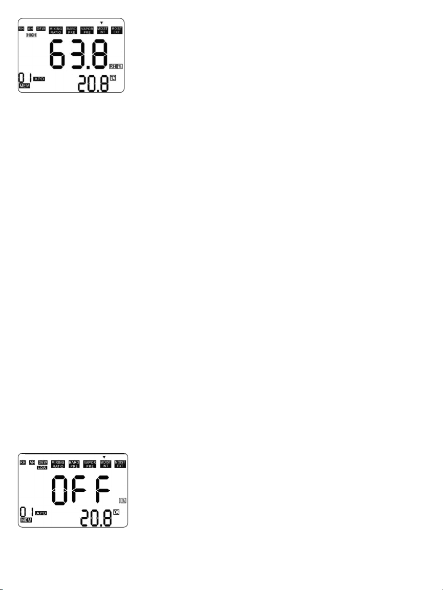
example, the screen shot at the top of the next page shows that the upper limit for RH—the
setpoint of the RH alarm—has been set to 63.8%.
HIGH
9
Page 12
T
o enter Alarm set mode
the same time while in
, press the
RH, MOIST INT
MAX/MIN
or
MOIST EXT
and
UNIT
mode. Doing so
buttons at
will display the current value of the selected parameter’s high
HIGH
setpoint and cause the word
to appear near the upper left of
the display, as shown on the left.
All three parameters require you to use the same three-step
sequence of button presses for changing their setpoint(s). After
entering Alarm set mode (with
setpoint by using the
LOW
setpoint). Each press of the
<DN
button decreases the setpoint by 0.1%. To change the value of the setpoint by a large
UP>
or
amount, you can press and hold the
Whether or not you change the
proceed to the next step in the sequence: changing the
Pressing the
STORE/ENTER
button with
readout as the selected parameter’s new
switches the primary readout to show the current value of the parameter’s
LOW
Once
parameter’s
you can leave the
must be to press the
appears on-screen, you can use the
setpoint, as explained earlier in the paragraph on
LOW
LOW
setpoint unchanged. Whether or not you make a change, your next step
STORE/ENTER
readout as the selected parameter’s new
appearing on screen), you can either raise or lower the
HIGH
<DN
button, or leave it unchanged (if you wish to change only the
UP>
button increases the setpoint by 0.1%. Each press of the
UP>
or
<DN
button for at least 3 seconds.
setpoint, you must press the
HIGH
HIGH
on-screen saves the value shown on the primary
HIGH
setpoint. It also changes
UP>
or
STORE/ENTER
LOW
setpoint or leaving it unchanged.
HIGH
<DN
button to change the value of the
setpoints. Alternatively,
HIGH
to
LOW
button to
LOW
setpoint.
button. Doing so saves the value shown on the primary
LOW
setpoint. It also causes
LOW
to disappear and
HIGH
and
returns the RH650 to operation in real-time RH measurement mode.
To disarm any of the six alarms(HIGH
reset its setpoint to 100.0% or 0.0% by pressing the
alarm, it is faster to use the
UP>
and
LOW
for
RH, MOIST INT
UP>
or
and
MOIST EXT
<DN
button. When disarming a
), you must
button to increase its setpoint to 100% than to use the
HIGH
<DN
button to decrease its setpoint to 0.0%. In practice, what you would do is: 1) press and hold the
UP>
button until the display shows a value greater than 99%, 2) release the button, and 3) use
brief presses to reach 99.9%. When the primary readout shows 99.9%, the next press of the
button will change the readout to
HIGH
the
alarm for that parameter.
Similarly, you would disarm a
OFF
. Pressing the
LOW
alarm by 1) pressing and holding the
STORE/ENTER
button at this point will disarm
<DN
button until the
UP>
display shows a value less than 1%, 2) releasing the button, and 3) using brief presses to reach
0.1%. When the primary readout shows 0.1%, the next press of the
button will change the readout to
<DN
STORE/ENTER
button at this point will disarm the
. Pressing the
OFF
alarm for that
LOW
parameter. The screen at left shows the next-to-last step (prior to
pressing the
MOIST INT
.
STORE/ENTER
button) of disarming the
LOW
alarm for
10
Page 13

Two notes related to alarms:
•
HIGH
alarm setpoints must be higher than
LOW
in Alarm set mode, pressing the
LOW
alarm setpoints. When the display is showing
STORE/ENTER
button to save a change that violates
this rule will not succeed in returning the RH650 to real-time measurement. Instead, the
beeper will sound four times and the Alarm set sequence will return to the first step.
Consider this a prompt to reset the
HIGH
alarm setpoint to a value greater than the
LOW
alarm setpoint.
HIGH
and
LOW
• The original factory settings of the
alarm setpoints are 85% and 25%,
respectively. So if your first use of the meter is in a exceptionally humid or dry environment,
an alarm may sound immediately. To disarm the alarm, follow the instructions in the
preceding two paragraphs.
MEASURING MOISTURE LEVELS
In addition to the modes for measuring five condensation-related parameters, the RH650 has two
separate moisture level measurement modes:
MOIST INT
and
MOIST EXT
. In
MOIST INT
mode,
the meter uses a non-invasive (pinless) sensor on the back of the unit to detect moisture on or
within 0.75 in. (19mm) of the surface of a material. In
MOIST EXT
mode, the meter uses the
included pin-type probe to measure the conductivity of a material as a proxy for its moisture
content.
In both moisture level measurement modes, the RH650’s display adds a vertical bar graph to the
digital readout of a material’s moisture level. The bar graphs (see below) have no scale; they
exist only to provide an analog way to quickly track changes in relative moisture levels.
To use the included pin-type probe to measure the moisture level of a material:
1. Use the
UP>
or
<DN
button to move the pointer above
MOIST EXT
.
2. Insert the plug of the probe into the jack on the bottom of the RH650.
3. Remove the protective cap from the business end of the probe and set it aside.
4. Insert the pins of the probe into the material whose moisture level you wish to measure.
The measured moisture level will appear on the primary readout as a percentage, with the
ambient temperature below it on the secondary readout.
To use the pinless sensor to measure the moisture level of a material
button to move the pointer above
MOIST INT
. Hold the meter in either hand by wrapping your
, use the
UP>
or
<DN
fingers around the rubber grip at the bottom of the unit. Make sure that no part of your hand or
fingers is touching—or even near—the pinless sensor on the back of the meter.
11
Page 14

If the primary readout shows
0.0%
with the meter in your hand (and not touching anything), the
meter is ready to make measurements. To measure the moisture level of a material, press the
pinless sensor on the back of the meter (Fig. 1, Callout L) against it. The moisture level, as
percentage, will appear on the primary readout.
If the primary readout shows a value other than 0.0%, you should reset the baseline of
measurements in
MOIST INT
nothing) and press the
bar graph at the left of the display, the primary readout will show
will again be accurate in
mode. To do so, continue to hold the meter in your hand (touching
ZERO
button. Immediately after the term
MOIST INT
mode.
ZERO
appears briefly below the
and the measurements
0.0%
To obtain accurate readings in
MOIST INT
mode, you should reset
the readout to 0.0% each time you re-enter that mode from
another mode.
CHECKING CALIBRATION
check
Although you cannot calibrate the RH650 yourself, you can
the meter’s calibration
periodically to assure yourself of the accuracy of humidity-related readings (RH, absolute
humidity, dew point and mixing ratio). Factory calibration should minimize the humidity sensor’s
drift for several years—well beyond the warranty period.
At a minimum, a calibration check should entail immersing the slotted structure protecting the
humidity sensor in two bottles containing saturated salts. One reference salt should produce a
reading of a 33%; the other should produce a reading of 75%.
Depending on the size and shape of the calibration salt bottle that you use, you may have to
remove the hanger tab (Fig. 1, Callout B) from the meter to provide sufficient clearance for the
bottle to fit snugly over the slotted structure protecting the humidity/temperature sensor (after
removing the dust cap). The hanger tab is removable for that reason.
12
Page 15

SPECIFICATIONS
Ambient Temperature Measurement Range -20° to 167°F (-29° to 75°C)/±3.6°F (2°C)
Ambient Temperature Measurement Accuracy±3.6°F (2°C)
RH Measurement Range 0 to 100%
RH Measurement Accuracy±2.5% from 11 to 90%RH; ±3%RH elsewhere
Absolute Humidity Range 0.5 to 240mg/m3(mg/L)
GPP Range 0 to 999 GPP (0 to 160g/kg)
Relative/Absolute Moisture Level Range 0 to 99.9%
Pinless Moisture Measurement Depth0.75 in. (19mm)
Dew Point Range -76° to 140°F (-60° to 60°C)
Atmospheric Pressure Range 30 to 120 kPA
Vapor Pressure Range 0 to 20.0 kPA
Sampling Rate 2X/sec
Memory Capacity 20 pairs of readings
Auto Power Off Trigger 30 minutes of inactivity
Backlight Duration 30 seconds
Battery Life 6 to 8 weeks (4 hrs/day use)
Operating Temperature 32° to 110°F (0° to 43°C)
Storage Temperature -22° to 140°F (-30° to 60°C)
Dimensions 7.3 x 2.8 x 1.4 in. (185 × 72 × 36mm)
Weight 6.2 oz. (175g), without battery
Power Source (1) “9V” battery (included)
13
Page 16

OPERATING & MAINTENANCE TIPS
• When the icon appears on the bottom row of the LCD, it’s time to install a fresh “9V”
battery using the procedure on p.7.
• Do not immerse the RH650 in water or get water on it.
• Do not disassemble the unit. Opening the case voids the warranty.
• To avoid fouling the humidity/temperature sensor, do not operate the unit in very dusty
environments. Replace the dust cap protecting the sensor after each measurement session.
• Remove the battery if you do not expect to use the unit for several months or longer. This will
avoid potential leaks of battery acid that might damage or destroy the unit.
14
Page 17

WARRANTY/ DISCLAIMER
OMEGA ENGINEERING, INC. warrants this unit to be free of defects in materials and workmanship
for a period of 13 months from date of purchase. OMEGA’s Warranty adds an additional one (1)
month grace period to the normal one (1) year product warranty to cover handling and shipping
time. This ensures that OMEGA’s customers receive maximum coverage on each product.
If the unit malfunctions, it must be returned to the factory for evaluation. OMEGA’s Customer
Service Department will issue an Authorized Return (AR) number immediately upon phone or
written request. Upon examination by OMEGA, if the unit is found to be defective, it will be repaired
or replaced at no charge. OMEGA’s WARRANTY does not apply to defects resulting from any action
of the purchaser, including but not limited to mishandling, improper interfacing, operation outside
of design limits, improper repair, or unauthorized modification. This WARRANTY is VOID if the
unit shows evidence of having been tampered with or shows evidence of having been damaged
as a result of excessive corrosion; or current, heat, moisture or vibration; improper specification;
misapplication; misuse or other operating conditions outside of OMEGA’s control. Components in
which wear is not warranted, include but are not limited to contact points, fuses, and triacs.
OMEGA is pleased to offer suggestions on the use of its various products. However,
OMEGA neither assumes responsibility for any omissions or errors nor assumes
liability for any damages that result from the use of its products in accordance with
information provided by OMEGA, either verbal or written. OMEGA warrants only that
the parts manufactured by the company will be as specified and free of defects. OMEGA
MAKES NO OTHER WARRANTIES OR REPRESENTATIONS OF ANY KIND WHATSOEVER,
EXPRESSED OR IMPLIED, EXCEPT THAT OF TITLE, AND ALL IMPLIED WARRANTIES
INCLUDING ANY WARRANTY OF MERCHANTABILITY AND FITNESS FOR A PARTICULAR
PURPOSE ARE HEREBY DISCLAIMED. LIMITATION OF LIABILITY: The remedies of
purchaser set forth herein are exclusive, and the total liability of OMEGA with respect
to this order, whether based on contract, warranty, negligence, indemnification, strict
liability or otherwise, shall not exceed the purchase price of the component upon which
liability is based. In no event shall OMEGA be liable for consequential, incidental or
special damages.
CONDITIONS: Equipment sold by OMEGA is not intended to be used, nor shall it be used: (1) as
a “Basic Component” under 10 CFR 21 (NRC), used in or with any nuclear installation or activity;
or (2) in medical applications or used on humans. Should any Product(s) be used in or with any
nuclear installation or activity, medical application, used on humans, or misused in any way,
OMEGA assumes no responsibility as set forth in our basic WARRANTY/ DISCLAIMER language,
and, additionally, purchaser will indemnify OMEGA and hold OMEGA harmless from any liability or
damage whatsoever arising out of the use of the Product(s) in such a manner.
RETURN REQUESTS/ INQUIRIES
Direct all warranty and repair requests/inquiries to the OMEGA Customer Service Department.
BEFORE RETURNING ANY PRODUCT(S) TO OMEGA, PURCHASER MUST OBTAIN AN AUTHORIZED
RETURN (AR) NUMBER FROM OMEGA’S CUSTOMER SERVICE DEPARTMENT (IN ORDER TO
AVOID PROCESSING DELAYS). The assigned AR number should then be marked on the outside
of the return package and on any correspondence. The purchaser is responsible for shipping charges,
freight, insurance and proper packaging to prevent breakage in transit.
FOR WARRANTY RETURNS, please have
the following information available BEFORE
contacting OMEGA:
1. Purchase Order number under which the
product was PURCHASED,
2. Model and serial number of the product under
warranty, and
3. Repair instructions and/or specific problems
relative to the product.
OMEGA’s policy is to make running changes, not model changes, whenever an improvement is possible. This
affords our customers the latest in technology and engineering.
OMEGA is a registered trademark of OMEGA ENGINEERING, INC.
© Copyright 2015 OMEGA ENGINEERING, INC. All rights reserved. This document may not be copied, photo-
copied, reproduced, translated, or reduced to any electronic medium or machine-readable form, in whole or in
part, without the prior written consent of OMEGA ENGINEERING, INC.
FOR NON-WARRANTY REPAIRS,
for current repair charges. Have the following
information available BEFORE contacting
OMEGA:
1. Purchase Order number to cover the COST
of the repair,
2. Model and serial number of the product, and
3. Repair instructions and/or specific problems
relative to the product.
consult OMEGA
Page 18

Where Do I Find Everything I Need for
Process Measurement and Control?
OMEGA…Of Course!
Shop online at omega.com
SM
TEMPERATURE
MU
Thermocouple, RTD & Thermistor
Probes, Connectors, Panels &
Assemblies
MU
Wire: Thermocouple, RTD &
Thermistor
MU
Calibrators & Ice Point References
MU
Recorders, Controllers & Process
Monitors
MU
Infrared Pyrometers
PRESSURE, STRAIN AND
FORCE
MU
Transducers & Strain Gages
MU
Load Cells & Pressure Gages
MU
Displacement Transducers
MU
Instrumentation & Accessories
FLOW/LEVEL
MU
Rotameters, Gas Mass Flowmeters
& Flow Computers
MU
Air Velocity Indicators
MU
Turbine/Paddlewheel Systems
MU
Totalizers & Batch Controllers
pH/CONDUCTIVITY
MU
pH Electrodes, Testers &
Accessories
MU
Benchtop/Laboratory Meters
MU
Controllers, Calibrators, Simulators
& Pumps
MU
Industrial pH & Conductivity
Equipment
DATA ACQUISITION
MU
Data Acquisition & Engineering
Software
MU
Communications-Based Acquisition
Systems
MU
Plug-in Cards for Apple, IBM &
Compatibles
MU
Data Logging Systems
MU
Recorders, Printers & Plotters
HEATERS
MU
Heating Cable
MU
Cartridge & Strip Heaters
MU
Immersion & Band Heaters
MU
Flexible Heaters
MU
Laboratory Heaters
ENVIRONMENTAL
MONITORING AND CONTROL
MU
Metering & Control
Instrumentation
MU
Refractometers
MU
Pumps & Tubing
MU
Air, Soil & Water Monitors
MU
Industrial Water & Wastewater
Treatment
MU
pH, Conductivity & Dissolved
Oxygen Instruments
M5505/1015
 Loading...