

Page 1
Page 2

OMEGAnet®Online Service Internet e-mail
omega.com [email protected]
Servicing North America:
U.S.A.: Omega Engineering, Inc., One Omega Drive, P.O. Box 4047
ISO 9001 Certified Stamford, CT 06907-0047 USA
Canada: 976 Bergar
Laval (Quebec), Canada H7L 5A1
Toll-Free: 1-800-826-6342 TEL: (514) 856-6928
FAX: (514) 856-6886 e-mail: [email protected]
For immediate technical or application assistance:
U.S.A. and Canada: Sales Service: 1-800-826-6342/1-800-TC-OMEGA
Customer Service: 1-800-622-2378/1-800-622-BEST
Engineering Service: 1-800-872-9436/1-800-USA-WHEN
Mexico: En Español: 001 (203) 359-7803 FAX: (001) 203-359-7807
®
®
®
Servicing Europe:
Benelux: Managed by the United Kingdom Office
Czech Republic: Frystatska 184
733 01 Karviná, Czech Republic
Toll-Free: 0800-1-66342 TEL: +420-59-6311899
FAX: +420-59-6311114 e-mail: [email protected]
France: Managed by the United Kingdom Office
Toll-Free: 0800 466 342 TEL: +33 (0) 161 37 29 00
FAX: +33 (0) 130 57 54 27 e-mail: [email protected]
Germany/Austria: Daimlerstrasse 26
D-75392 Deckenpfronn, Germany
Toll-Free: 0 800 6397678 TEL: +49 (0) 7059 9398-0
FAX: +49 (0) 7056 9398-29 e-mail: [email protected]
United Kingdom: OMEGA Engineering Ltd.
ISO 9001 Certified One Omega Drive, River Bend Technology Centre, Northbank
Irlam, Manchester M44 5BD England
Toll-Free: 0800-488-488 TEL: +44 (0)161 777-6611
FAX: +44 (0)161 777-6622 e-mail: [email protected]
It is the policy of OMEGA Engineering, Inc. to comply with all worldwide safety and EMC/EMI
regulations that apply. OMEGA is constantly pursuing certification of its products to the European New
Approach Directives. OMEGA will add the CE mark to every appropriate device upon certification.
The information contained in this document is believed to be correct, but OMEGA accepts no liability for any
errors it contains, and reserves the right to alter specifications without notice.
WARNING: These products are not designed for use in, and should not be used for, human applications.
Page 3

WARRANTY/DISCLAIMER
OMEGA ENGINEERING, INC. warrants this unit to be free of defects in materials and workmanship for a
period of 13 months from date of purchase. OMEGA’s WARRANTY adds an additional one (1) month
grace period to the normal one (1) year product warranty to cover handling and shipping time. This
ensures that OMEGA’s customers receive maximum coverage on each product.
If the unit malfunctions, it must be returned to the factory for evaluation. OMEGA’s Customer Service
Department will issue an Authorized Return (AR) number immediately upon phone or written request.
Upon examination by OMEGA, if the unit is found to be defective, it will be repaired or replaced at no
charge. OMEGA’s WARRANTY does not apply to defects resulting from any action of the purchaser,
including but not limited to mishandling, improper interfacing, operation outside of design limits,
improper repair, or unauthorized modification. This WARRANTY is VOID if the unit shows evidence of
having been tampered with or shows evidence of having been damaged as a result of excessive corrosion;
or current, heat, moisture or vibration; improper specification; misapplication; misuse or other operating
conditions outside of OMEGA’s control. Components in which wear is not warranted, include but are not
limited to contact points, fuses, and triacs.
OMEGA is pleased to offer suggestions on the use of its various products. However,
OMEGA neither assumes responsibility for any omissions or errors nor assumes liability for any
damages that result from the use of its products in accordance with information provided by
OMEGA, either verbal or written. OMEGA warrants only that the parts manufactured by it will be
as specified and free of defects. OMEGA MAKES NO OTHER WARRANTIES OR
REPRESENTATIONS OF ANY KIND WHATSOEVER, EXPRESS OR IMPLIED, EXCEPT THAT OF TITLE,
AND ALL IMPLIED WARRANTIES INCLUDING ANY WARRANTY OF MERCHANTABILITY AND
FITNESS FOR A PARTICULAR PURPOSE ARE HEREBY DISCLAIMED. LIMITATION OF
LIABILITY: The remedies of purchaser set forth herein are exclusive, and the total liability of
OMEGA with respect to this order, whether based on contract, warranty, negligence,
indemnification, strict liability or otherwise, shall not exceed the purchase price of the
component upon which liability is based. In no event shall OMEGA be liable for
consequential, incidental or special damages.
CONDITIONS: Equipment sold by OMEGA is not intended to be used, nor shall it be used: (1) as a “Basic
Component” under 10 CFR 21 (NRC), used in or with any nuclear installation or activity; or (2) in medical
applications or used on humans. Should any Product(s) be used in or with any nuclear installation or
activity, medical application, used on humans, or misused in any way, OMEGA assumes no responsibility
as set forth in our basic WARRANTY/ DISCLAIMER language, and, additionally, purchaser will indemnify
OMEGA and hold OMEGA harmless from any liability or damage whatsoever arising out of the use of the
Product(s) in such a manner.
RETURN REQUESTS/INQUIRIES
Direct all warranty and repair requests/inquiries to the OMEGA Customer Service Department. BEFORE
RETURNING ANY PRODUCT(S) TO OMEGA, PURCHASER MUST OBTAIN AN AUTHORIZED RETURN
(AR) NUMBER FROM OMEGA’S CUSTOMER SERVICE DEPARTMENT (IN ORDER TO AVOID
PROCESSING DELAYS). The assigned AR number should then be marked on the outside of the return
package and on any correspondence.
The purchaser is responsible for shipping charges, freight, insurance and proper packaging to prevent
breakage in transit.
FOR WARRANTY
following information available BEFORE
contacting OMEGA:
1. Purchase Order number under which the product
was PURCHASED,
2. Model and serial number of the product under
warranty, and
3. Repair instructions and/or specific problems
relative to the product.
OMEGA’s policy is to make running changes, not model changes, whenever an improvement is possible. This affords
our customers the latest in technology and engineering.
OMEGA is a registered trademark of OMEGA ENGINEERING, INC.
© Copyright 2009 OMEGA ENGINEERING, INC. All rights reserved. This document may not be copied, photocopied,
reproduced, translated, or reduced to any electronic medium or machine-readable form, in whole or in part, without the
prior written consent of OMEGA ENGINEERING, INC.
RETURNS, please have the
FOR NON-WARRANTY REPAIRS,
for current repair charges. Have the following
information available BEFORE contacting OMEGA:
1. Purchase Order number to cover the COST
of the repair,
2. Model and serial number of the product, and
3. Repair instructions and/or specific problems
relative to the product.
consult OMEGA
Page 4

Where Do I Find Everything I Need for
Process Measurement and Control?
OMEGA…Of Course!
Shop online at omega.com
sm
TEMPERATURE
䡺⻬
Thermocouple, RTD & Thermistor Probes, Connectors, Panels & Assemblies
䡺⻬
Wire: Thermocouple, RTD & Thermistor
䡺⻬
Calibrators & Ice Point References
䡺⻬
Recorders, Controllers & Process Monitors
䡺⻬
Infrared Pyrometers
PRESSURE, STRAIN AND FORCE
䡺⻬
Transducers & Strain Gages
䡺⻬
Load Cells & Pressure Gages
䡺⻬
Displacement Transducers
䡺⻬
Instrumentation & Accessories
FLOW/LEVEL
䡺⻬
Rotameters, Gas Mass Flowmeters & Flow Computers
䡺⻬
Air Velocity Indicators
䡺⻬
Turbine/Paddlewheel Systems
䡺⻬
Totalizers & Batch Controllers
pH/CONDUCTIVITY
䡺⻬
pH Electrodes, Testers & Accessories
䡺⻬
Benchtop/Laboratory Meters
䡺⻬
Controllers, Calibrators, Simulators & Pumps
䡺⻬
Industrial pH & Conductivity Equipment
DATA ACQUISITION
䡺⻬
Data Acquisition & Engineering Software
䡺⻬
Communications-Based Acquisition Systems
䡺⻬
Plug-in Cards for Apple, IBM & Compatibles
䡺⻬
Datalogging Systems
䡺⻬
Recorders, Printers & Plotters
HEATERS
䡺⻬
Heating Cable
䡺⻬
Cartridge & Strip Heaters
䡺⻬
Immersion & Band Heaters
䡺⻬
Flexible Heaters
䡺⻬
Laboratory Heaters
ENVIRONMENTAL
MONITORING AND CONTROL
䡺⻬
Metering & Control Instrumentation
䡺⻬
Refractometers
䡺⻬
Pumps & Tubing
䡺⻬
Air, Soil & Water Monitors
䡺⻬
Industrial Water & Wastewater Treatment
䡺⻬
pH, Conductivity & Dissolved Oxygen Instruments
M4818/1009
Page 5

INST.No.INE-418-1P1CE
Request and n otices
Please read this instruction manual for using this “Temperature/humidity meter”
correctly and safely.
Request t o instrumentati on manufacturers, i nstallation contract ors, a nd
sales ag ent s
Make sure to deliver this instruction manual to the operator of this “Temperature/humidity
meter”.
Request to the op erat o r of th i s temp er atu re /hu mid ity me ter
This instruction manual is ne cessary for main tenan ce, too.
Keep this manual with due care until thi s “Temperature/humidity meter” is disca rded.
Notices
1. The descriptions of this manual are subject to change without notice.
2. If a question has arisen or if an omission was found in this manual, please
contact your nearest OMEGA’s agent.
3. We are not responsible for any results by operation of this “Temperature/humidity
meter”.
-Preface 1-
Page 6
INST.No.INE-418-1P1CE
Important notices
The instruction manual f or the RH32 series pa lm-si zed tem perat ur e/ humidity meter is consisted of Vol. 1 [Basic instructions] and
Vo l. 2 [Function instructions].
This instruction manual is Vol. 1 [Basic instructions].
For “Measurement and data storage”, “Stored data reading” and “Parameter programming”, etc., refer to V ol. 2 [Function instructions].
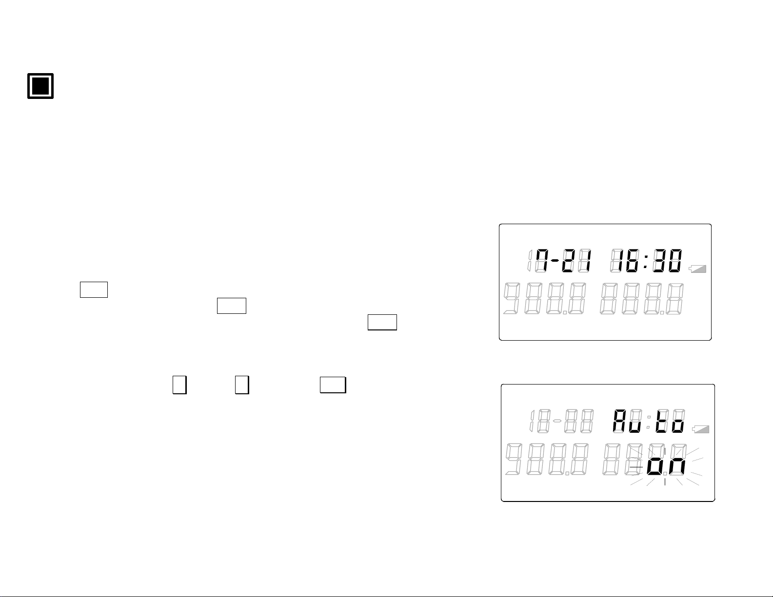
[Auto-power-off function]
For avoiding the comsumption of the batteries, the auto-power-off function
of this “temperature/humiditymeter” has been s et at ON (ac tive) as a factory
default setting. If no key is pressed for 1 minute, the continuous measurement
will automatically stop an d the mode will move to the clock mode.
For setting of the auto-power-off function to OFF:
Press DISP key to go to the continuous measurement mode ( Ref. [1.1Continuous
measureme nt] and then press DISP key again f or about 2 second s to go to
the programm ing mode. In th e programming m ode, press DISP k ey several
times to go to the auto-power-off selection mode with “Auto” lit in the sub
display. In the auto-power-off selection mode, “on” (active) will flash in the
main display 2. For releasing the auto-power-off function, select “oFF”
LOG TIME UNIT ALARM
TERM
READ
Auto-power-off selection mode
Clock mode
°
F
℃
REP
INT REF
LOCK
°FH
℃
%RH
H
(release) by pressing ∧ key or ∨ key. Press ENT key to retain “oFF”
selected. The flashing of “oFF ”will stop.
For the RS-232C communications with Model RH32-C2 (RS-232C
communications type), the use of the AC power adapter (RH32-AC110 - sold
separately) is recommended to avoid the consumption of the batteries.
Also, for the RS-485 communications with Model RH32-C4 (RS-485
communications type), make sure to use the AC power adapter
(RH32-AC110 - sold separately) as the batteries will be consumed very rapidly .
-Preface 2-
LOG TIME UNIT ALARM
TERM
READ
REP
°
F
℃
INT REF
LOCK
°FH
℃
%RH
H
Page 7
INST.No.INE-418-1P1CE
W arning and safety notices
Ensure the following instructions to use this meter correctly.
!
!
!
!
!
!
Warning (For avoiding unexpected dangerous accidents of death or serious injury)
◆ Don’t use this meter in places where explosive gas exists.
◆ If this meter is smoking, nasty smelling or abnormal noising, remove batteri es from it or pull out an AC
power adapter (RH32-AC110) (if used) from a receptacle as quickly as possible, and then contact your
OMEGA ’ s agent.
◆ Don’t throw out batteries in fire. Don’t charge, short circuit, heat or disassemble them.
It will cause a fire or an injury by blowing-out or heat.
◆ For the AC power adapter , use the power voltage of 100 to 240V.
Don’t touch the AC power adapter or the receptacle by wet hands. It will cause an electric shock, a fire
or a failure.
Wipe out dusts from the AC power adapter to prevent fires.
◆ Don’t touch the inside of the case by wet hands.
◆ Don’t repair or modify it.
!
!
◆ Check the specifications of batteries. Use AA (UM-3) batteries.
◆ Don’t use it under failed conditions.
-Preface 3-
Page 8

INST.No.INE-418-1P1CE
Contents
Palm-sized tempera tur e/humidit y meter <Vol.1 [Basic in structio ns]>
Request and notices
Importance notices
Warning and safety notices
1. Introduction·························································1
1.1 Outl in e ··································································1
1.2 Co nfiguration······ ·············· ··············· ·············· ········1
2. Model and accessories·······································3
2.1 Model·····································································3
2.2 Access ories·····························································3
3. Overviews and functions····································4
3.1 Overvie ws and functions : Front view ···················4
3.2 Overvie ws and functions : Side v iew·····················4
3.3 Display··································································6
4. Installation···························································8
4.1 Using as a handhel d type·······································8
4.2 Using as a wall ins tal l a tion type·····························9
4.3 Using as a desk top ins tal lation type·····················10
5.2.4 Retaining of hour ················· ························· 14
5.2.5 Retaining of minute··· ································ ···· 14
5.2.6 Retaining of year··········································· 14
5.2.7 Retaining of clo ck················ ························· 14
5.3 Measurement preparation···································16
5.3.1 Measurement unit s election mode················· 16
5.3.2 Temperature measurement unit ····················· 16
6. Continuous measurement······························ 18
6.1 Continuous measurement mode·························18
6.2 Measured temperature/humidity display range···19
7. Repl ac emen t of tem pe rat ur e /hu mid it y se ns or20
8. Working environment···································· 23
9. Troubleshooting··············································· 24
10. Specifications················································· 26
5. Measurement for preparation························11
5.1 Loading of batte ry (AA=UM-3)··························11
5.2 Clock adjus tmen t of cl ock···································13
5.2.1 Cl ock adj ust men t mode·····································13
5.2.2 R etai ni ng of month············································13
5.2.3 R etai ni ng of day················································13
11. External dimensions····································· 27
11.1 Ex ternal dimensions of RH32B-C··················27
11.2 External dimensions of RH32P-C ··················28
11.3 External dimensions of RH32S-C ··················28
-Content-
Page 9
INST.No.INE-418-1P1CE
1. Introduction
1. 1 Outline
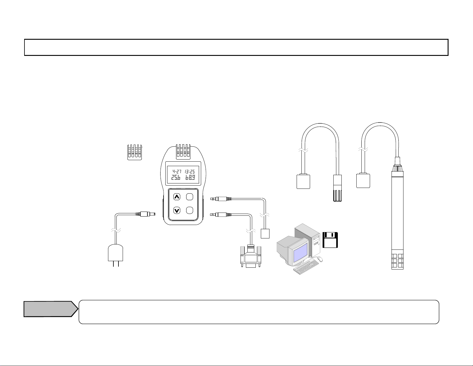
The RH32 series is a high performance and highly reliable palm-sized temperature/humidity meter for the measurement of
temperature and humidity of 0 t o 100%R H using a capa citance type humidity sens or.
The meter has two major functions, “measurem ent of te m perature a nd hum idity” an d “data loggin g of ma xim um 8000 data of
both temperature an d humidity” (Refer to the separated instruction manual Vol. 2 <Function instructions>). In addition, by
using a data logging softwa re package (sold sepa rately), easy data proc essing by a PC is a vailable .
1.2 Configuration
Built - in type sensor
RH32B-RP
Note : Sold sep aratel y
AC power adapter
RH32-AC1 10*
LOG ALARM
℃
%RH
LOCK
DISP
SHIFT
LOCK
ENT
LOG
Temperature/humidity meter
RH32B-C2
RH32P-C2
RH32S-C2
RH32B-C4 *
RH32P-C4 *
RH32S-C4 *
Separated type senso r
RH32S-RP
RS-485
communications cable
RH32-S4-CABLE* Note)
RS-232C
communications cable
RH32-S2-CABLE Note)
Data logging
software p ackage
RH32-SW1 Note)
RH32-SW2 Note)
Probe type
sensor
RH32P-RP
Caution
* For the RS-485 communications with Model RH32-C4 (RS-485 communications type), make sure to
use the AC power adapter (RH32-AC110 - sold separately) as the batteries will be consumed very rapidly.
-1-
Page 10

INST.No.INE-418-1P1CE
conformance
Palm-sized temperature/humidity meter
RH32B-C2,RH32P-C2,RH32S-C2 ,
RH32B-C4,RH32P-C4,RH32S-C4
Directive
89/336/EEC,92 /31/EEC amendment,
93/68/EEC amendment
Standard
EN61326+A1: Emission class B,
Conformance condition
RH32B-C4:The connection cable is to be used indoor
RH32S-C4,RH32P-C4:The connection cable is to be
Stability under the test environment of EMC directive
Temperature ±0.5ºC
Immunity Table1
(Minimum immunity test requirements)
and within 30m.
within 3m .
AC power adapter
RH32-AC1 10
EMI standard
Meets the conduction limit of : FCC Clas s B EN61000-3-2
EN55022 B EN61000-3-3
VCCI II
EMS EN50082-1
IEC801-2 Level3
IEC801-3
IEC801-4
Relative humidity ±3%RH
-2-
Page 11
INST.No.INE-418-1P1CE
2. Model and accessories
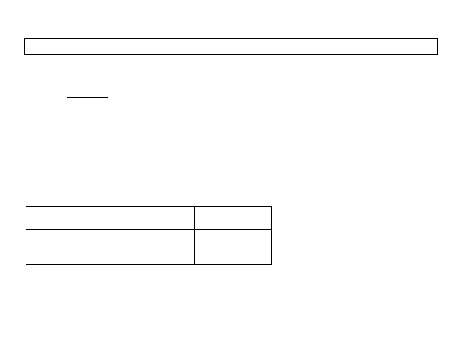
2.1 Model
RH32 -C
Temperature/humidity sensor
B: Built-in type
P: Probe type (Cable length: 1.5m)
S: Separated type (Cable length: 1.5m)
Communications interface
2: RS-232C
4: RS-485
2.2 Accessories
Accessories Qty. Remarks
Desktop attachment 1
AA (UM-3) alkaline battery 2
Vol.1 Basic instructions 1 This manual
Vol.2 Function instructions 1 Separate manual
-3-
Page 12
INST.No.INE-418-1P1CE
3. Overviews and functions
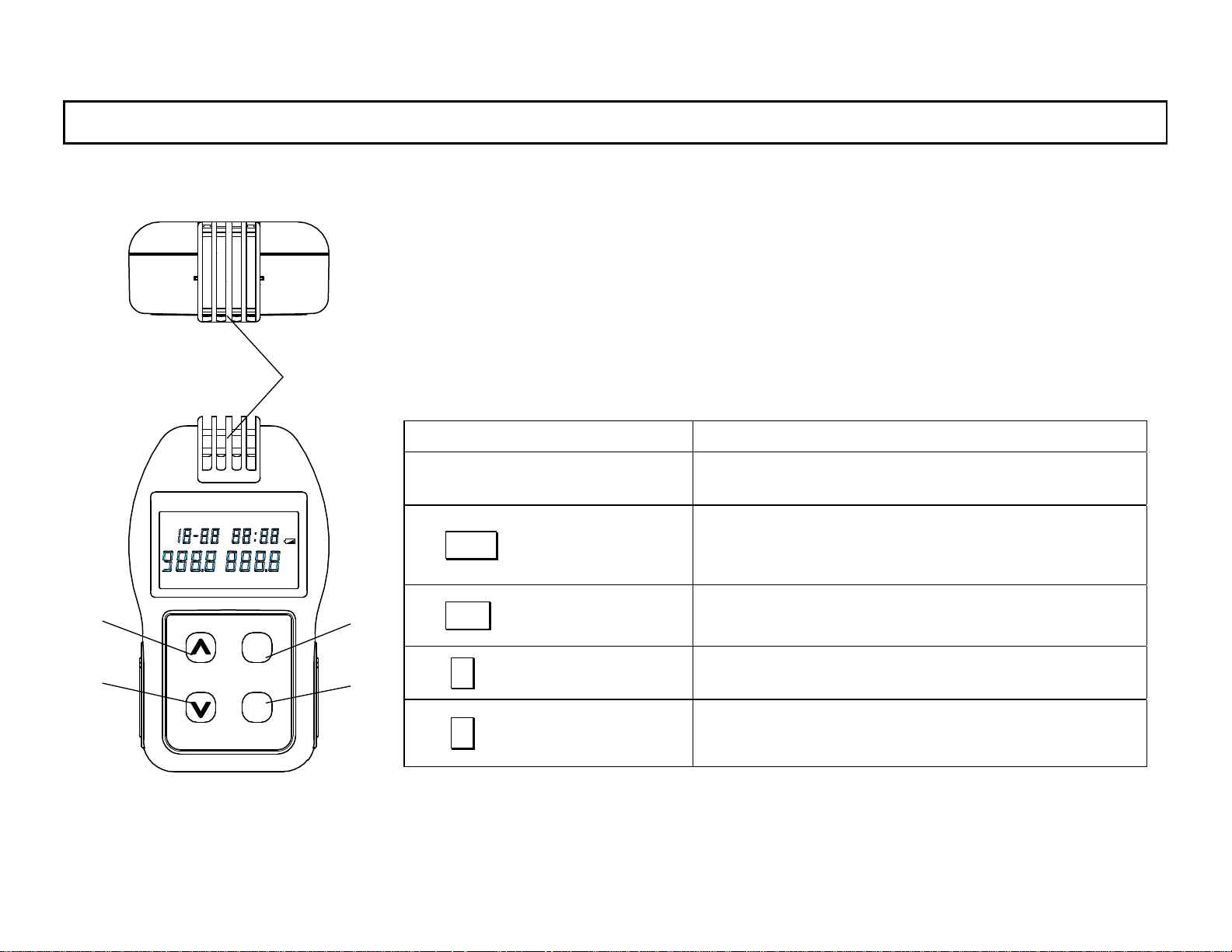
3.1 Overviews and functions : Front view
(4)
(5)
READLOG TIME UNIT ALARM
°
F
REP
SHIFT
℃
INT R EF
TERM
DISP
LOCK
ENT
LOG
LOCK
(1)
°FH
℃
%RH
(The figures shown are for Model RH32B-C. For Model RH32P-C and
Model RH32S-C, refer to [11.2 External dimensions of RH32P-C] and
[11.3 External dimensions of RH32S-C].)
Article Function
(1) T emperature/humidity
T emperature a nd humidity sensors built-in
sensor
To go to the continuous measurement mode or the
H
(2) DISP (LOCK) key
programming mode from clock mode, or to set
the key lock function
(2)
(3)
(3) ENT (LOG) key
(4) ∧ (SHIFT) key
(5) ∨ key
To retain the parameter programmed, or to
start/stop data logging
To increase a numerical figure and shift a key
function.
To decrease a numerical figure in the programming m ode
-4-
Page 13
INST.No.INE-418-1P1CE
3. Overviews and functions
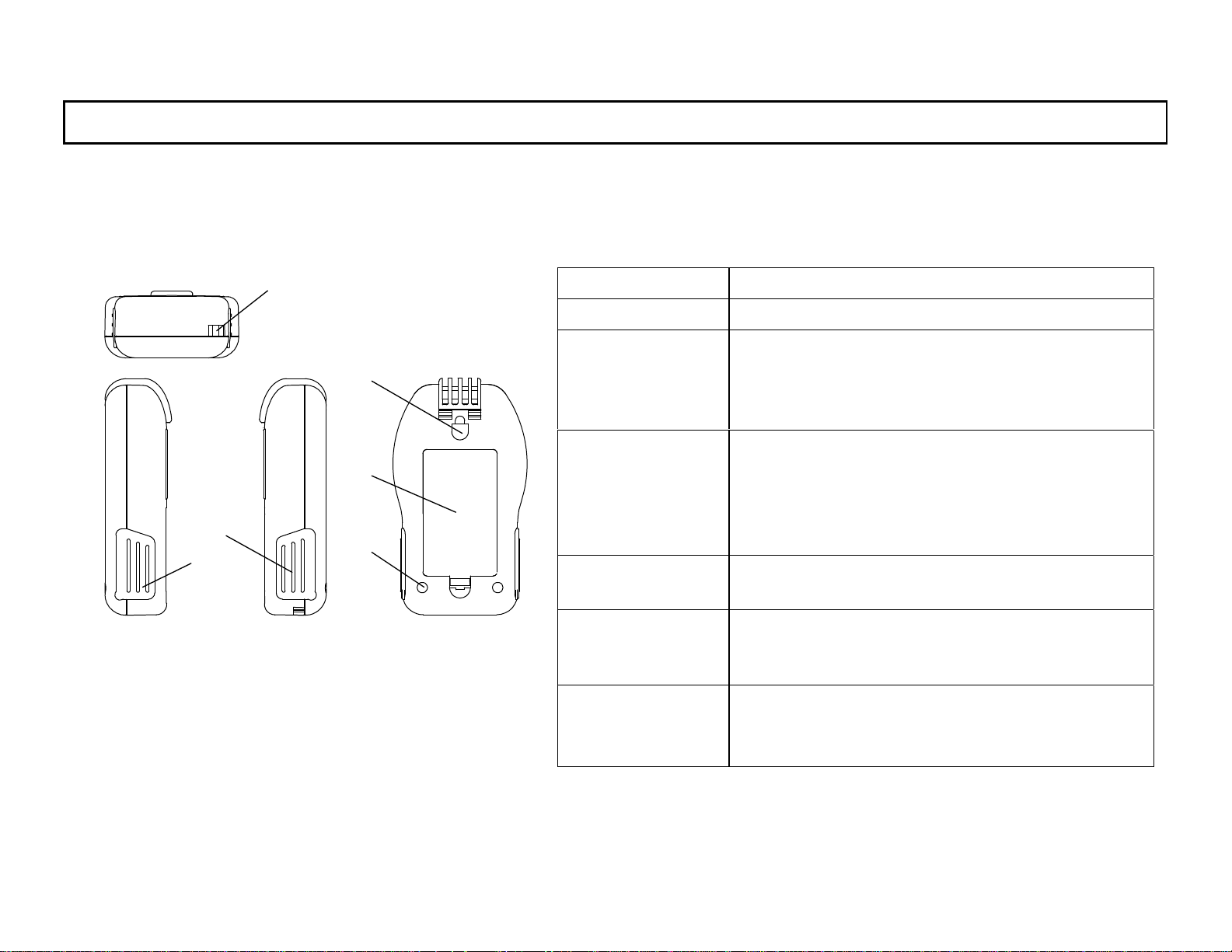
3.2 Overviews and functions : Side view
(The figures shown are for Model RH32B-C. For Models RH32P-C and RH32S-C, refer to [11.2 External
dimensions of RH32P-C] a nd [1 1.3 External dim ensions of RH32S-C].)
(6)
(9)
(10)
Article Function
(6)Hole for strap The hole for attaching a strap
(7)Cover for AC
power
adapter jack
(8)Cover for
communica-
(7)
(8)
(11)
tions jack
(9)Hole for wall
installation
(10)Battery
cover
(11)Holes f or
desktop
attachment
The cover for the jack to connect the AC power adapter (RH32-AC110)
For opening the cover, pull up it from the lower side.
The cover for the jack to connect the RS-232C
communications cable (RH32-S2-CABLE) or
the RS-485communications cable
(RH32-S4-CABLE). For opening the cover,
pull up it from the lower side.
The hole for hooking this meter to a wall using
a M4 screw or a nail
The cover for the AA battery compartment.
For opening it, push it upward by picking up
the nail of a lower part.
The holes for mounting the attachment for th e
desktop installation.
-5-
Page 14
INST.No.INE-418-1P1CE
3. Overviews and functions
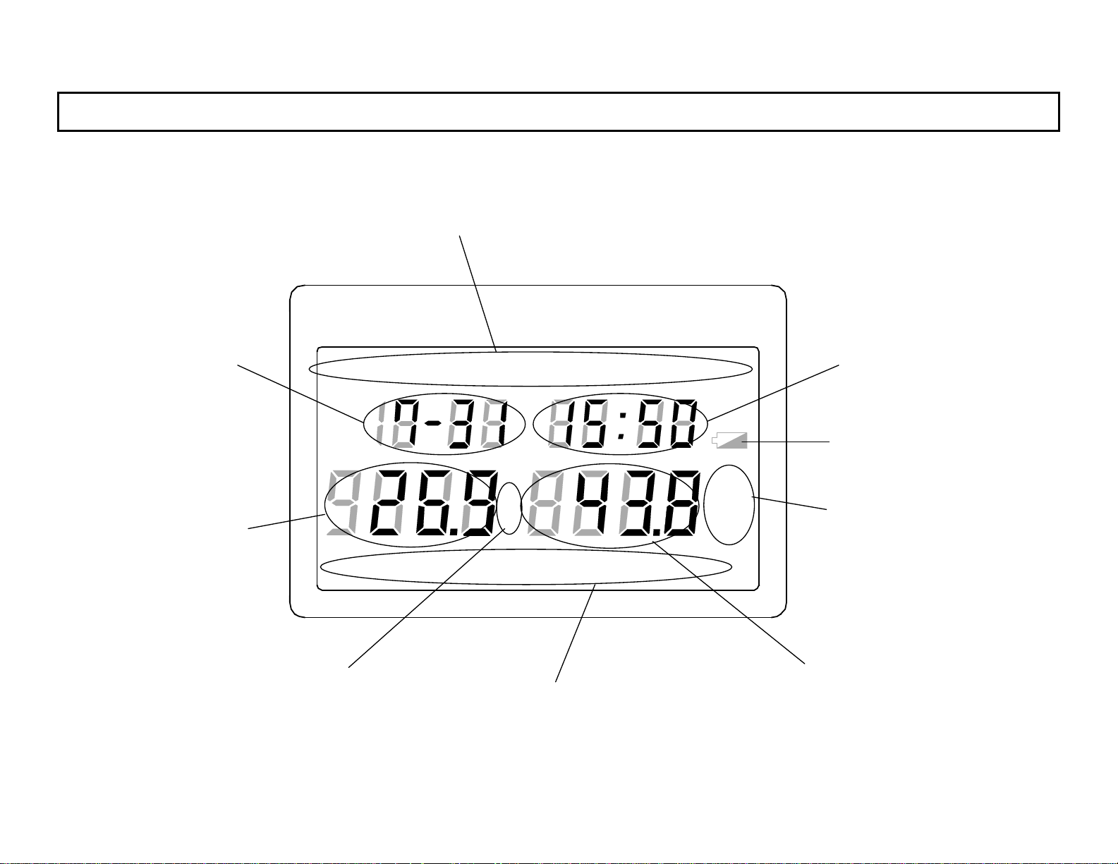
3.3 Display
(2) Month/day
(1) Main marker
READLOG TIME UNIT ALARM
(3) Sub display
(8) Low battery mark
°
(4) Main display 1
(6) T emperature measurement unit
TERM
REP
F
℃
INT RE F
(1) Main marker
-6-
LOCK
°FH
℃
%RH
H
(7) Humidity measurement
unit/totalized
temperature measurement
unit
(5) Main d ispla y 2
Page 15
INST.No.INE-418-1P1CE
3. Overviews and functions
LOG
READ
TIME
(1)Main
marker
(2) Month/day Month/day
(3) Sub display
(4) Main display 1 Temperature measured value
(5) Main display 2 Humidity measured value
(6) Temperature
measurement unit
(7) Humidity
measurement
unit/totalized
temperature
measurement
unit
(8) Low battery
mark
UNIT
ALARM
TERM
REP
INT
REF
%RH
º CH
º FH
Data storage
Reading
Month/day/hour/minute
Temperature measurement unit
/humidity measurement unit
Alarm
Start/stop
Repetition
Interval time
Totalizing reference
Hour/minute and
parameter item
ºC
ºF
Relative humidity
ºC/ºCH
ºF/ ºFH
Low battery mark
Lights during manual or automatic storage
Lights when stored data are read.
Lights when year, month, day and time are programmed.
Lights in endless storage by using the data logging software package
(sold separately).
Lights when the temperature measurement unit (ºC/ºF) or the relative humidity/the dew-point temperature measurement unit (%RH/ºC/ºF) is set.
Lights when an alarm is activated or alarm setpoints are programmed.
Lights when storage start and stop time of the automatic storage are
programmed.
Lights when storage repetition is programmed.
Lights when storing interval is programmed.
Lights when totalizing reference temperature is programmed.
Displays month and day.
Displays hour and minute when “TIME” or “TERM” lights in the main marker,
or displays a parameter item in other cases.
Displays measured temperature or totalized tem peratu re.
Displays measured relative humidity, measured dew-point temperature, or
totalized temperature.
Lights when measured temperature is displayed in ºC.
Lights when measured temperature is d isplayed in ºF.
Lights when relative humidity is displayed.
ºC lights when dew-point temperature and ºC temperature are displayed.
ºCH lights when totalized temperature and ºC temperature are displayed.
ºF lights when dew-point temperature and ºF temperature are displayed.
ºFH lights when totalized temperature and ºF temperature are displayed.
Lights when battery voltage becomes low er.
-7-
Page 16
INST.No.INE-418-1P1CE
4. Installation
4.1 Using as a handheld type
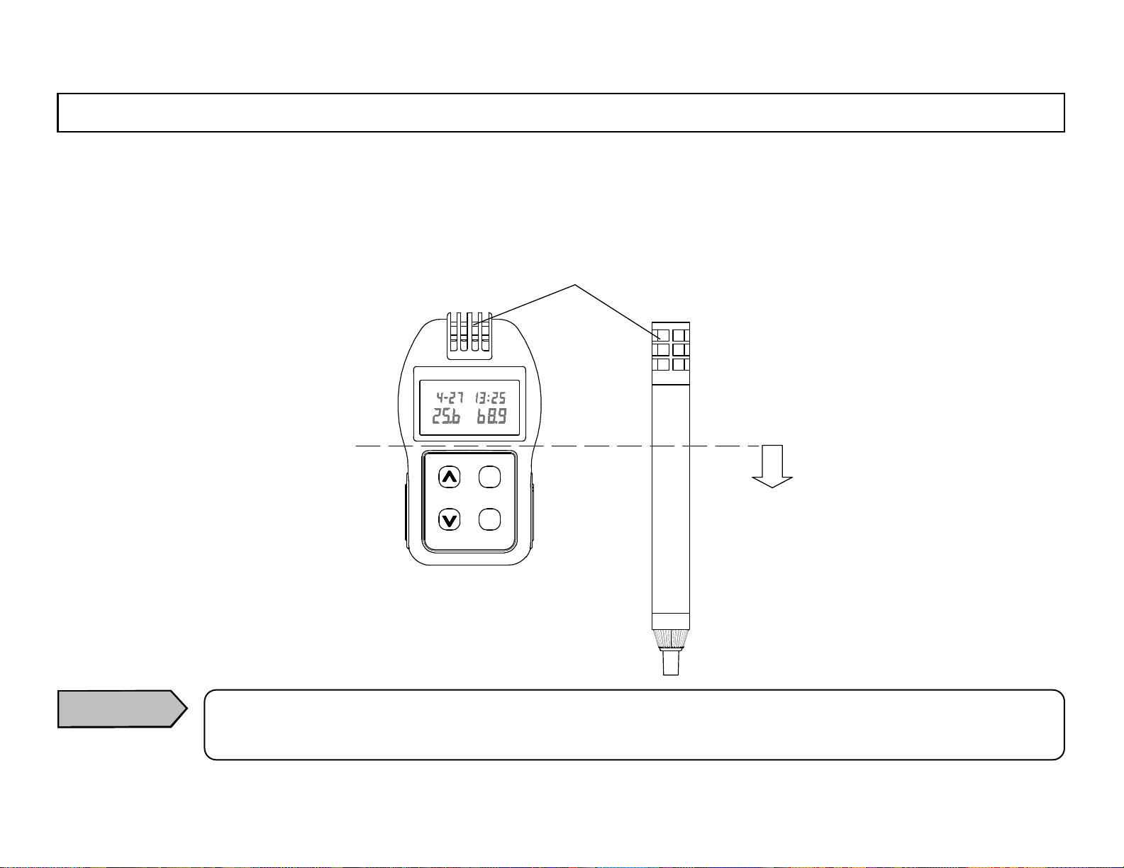
When this meter is used as a handheld type, be careful not to cover the temperature/humidity sensor by hands or not to touch it
by fingers. For the built-in type sensor, m ake sure to hold the lower ha lf o f t his m ete r.
T em perature /humidity se nsor
LOG ALARM
℃
LOCK
%RH
SHIFT
DISP
LOCK
ENT
LOG
Hold lower than this position.
Caution
If the temperature/humidity sensor is covered by hands or touched by fingers, accurate temperature/humidity measurement is not possible.
-8-
Page 17
INST.No.INE-418-1P1CE
4. Installation
4.2 Using as a wall installation t ype
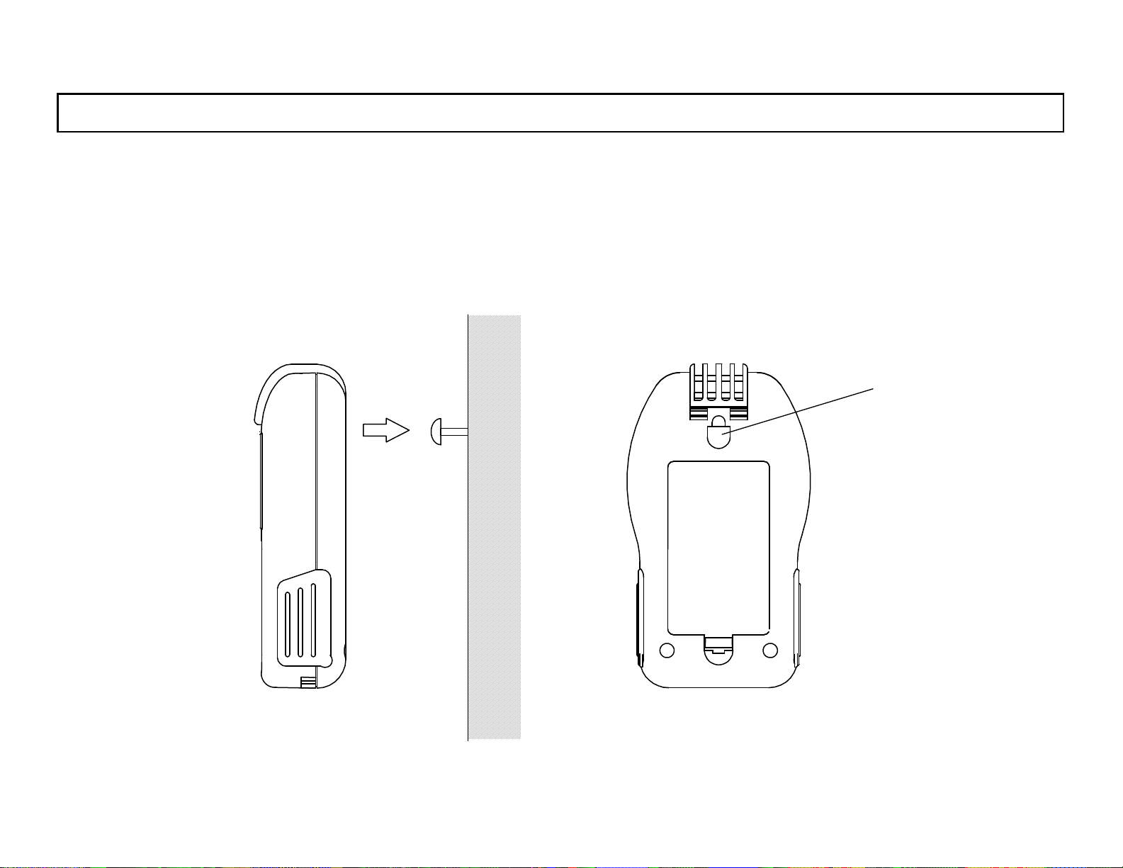
When this meter is used as a wall installation type, hook the wall installation hole on the backside of this m eter to a M4 screw or
a nail mounted to the wall.
Wall installation hole
-9-
Page 18
INST.No.INE-418-1P1CE
4. Installation
4.3 Using as a desktop installation type
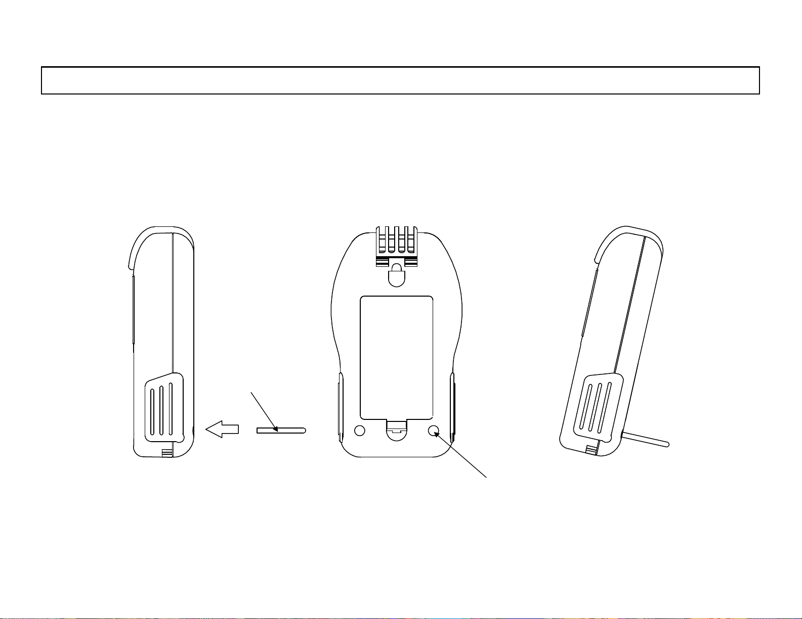
When this meter is used as a desktop installation type, insert the desktop attachment to the hole s for the desktop installation.
Desktop attachment
Hole for desktop attachment
-10-
Page 19
INST.No.INE-418-1P1CE
5. Measurement preparation
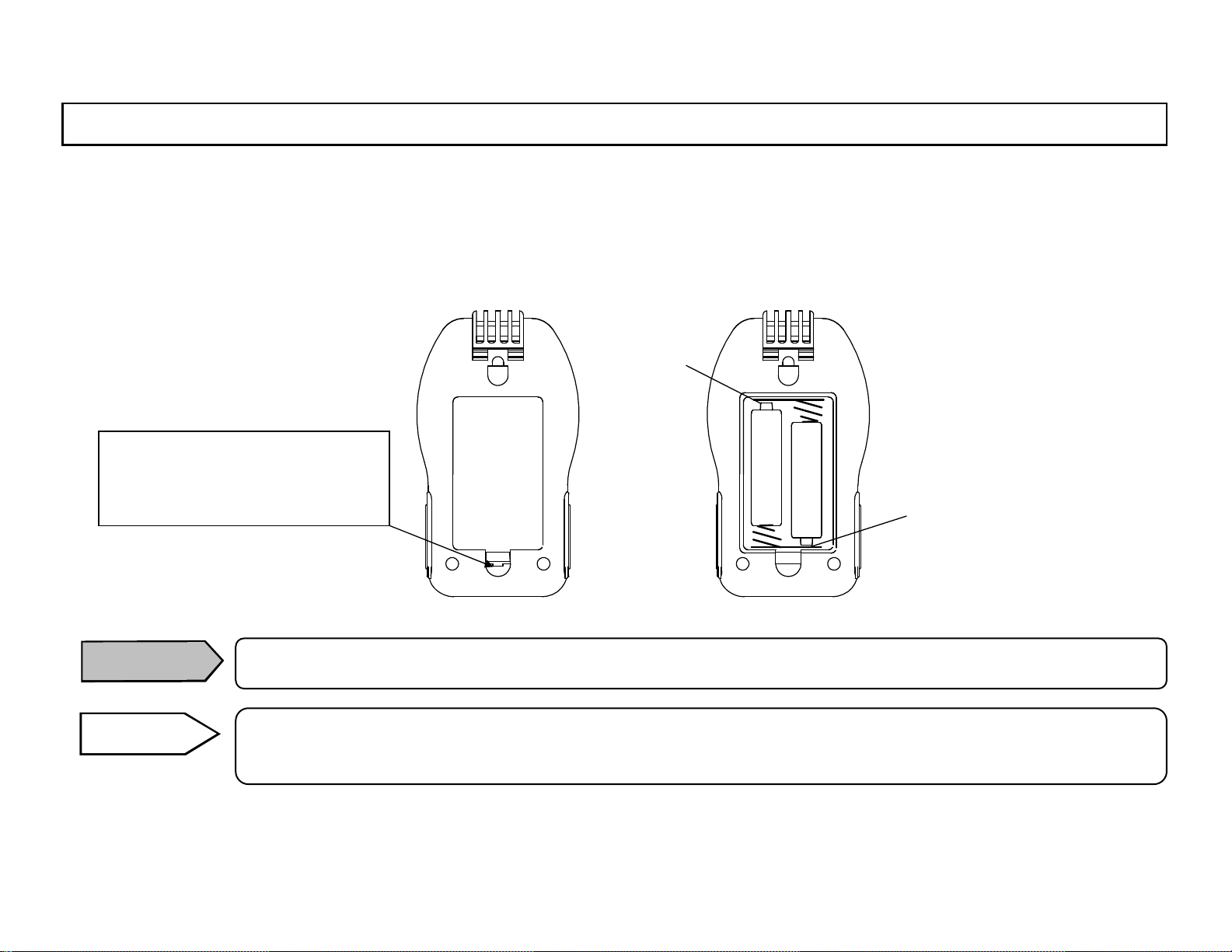
5.1 Loading of battery (AA=UM-3)
This meter is operated by two AA (UM-3) alkaline batteries.
Open the battery cover and load the batteries with correct polarities.
For opening the battery cover,
push it lightly upward by lifting
up the nail.
+ polarity
+ polarity
Caution
Reference
Note : Sold separately
Load the batteries with correct polarities.
In operation of this meter with the AC power adapter (RH32-AC110* Note) only, the loading of the
batteries is not required.
-11-
Page 20
INST.No.INE-418-1P1CE
)
d
j
)
5. Measurement preparation
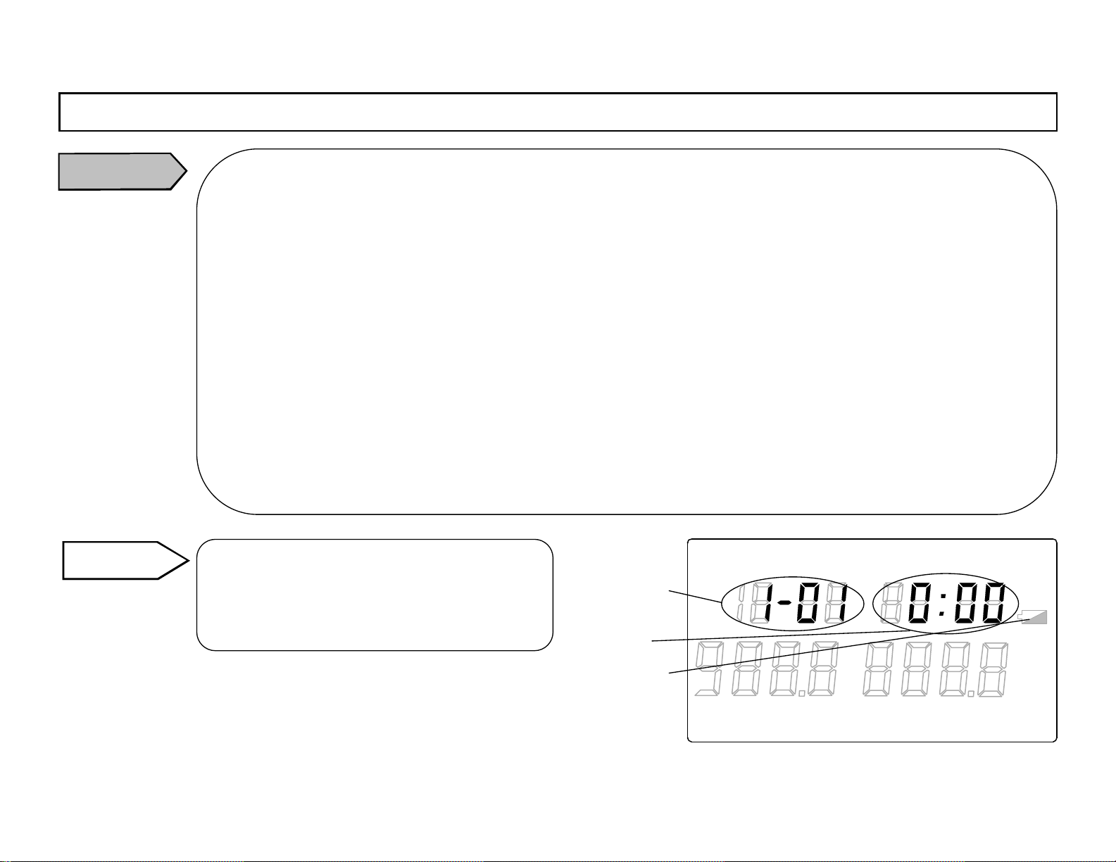
Caution
Batte ry life
When the battery voltage becomes lower, the low battery mark will light. Replace the batteries with new ones.
If you use this meter w ith the low battery m ark being lit, “Er 4” will be displ ayed in the main display 2.
Replace the batteries with new one s.
When any displays are not shown, the batteries voltage becomes lower. Replace the batteries with new ones.
Battery re placement
Replace 2 batteries together .
Batte ry polarities
Load the batteries with correct polarities.
When the AC powe r adapter is used:
The low battery mark will not light.
If “Er4 ” displays in the main display 2, take the following proce dures.
1)Remove the AC power adapter from this meter .
2)After then, take off the batteries or re place them into new ones.
3)Connect the AC power batteries again.
Note
The clock will stop (reset) by the above procedure, adjust the clock. (Refer to [5.2 Clock a
ustment].
Reference
S top of clock in battery repla cement
When the clock stops in the battery
replacement, the clock will start from
0 hour 00 minute, January 1
st
, 2001 after the
loading of the new batteries.
Month/day
display part
Sub display
Low battery ma rk
LOG TIME UNIT ALARM
READ
°
℃
F
%RH
°FH
℃
H
After the loading of the new batteries, month and day are displayed in
the month/day display part, and hour and minute are displayed in the
TERM
REP
INT REF
LOCK
sub display.
-12-
Page 21
INST.No.INE-418-1P1CE
5. Measurement preparation
5.2 Clock adju stment
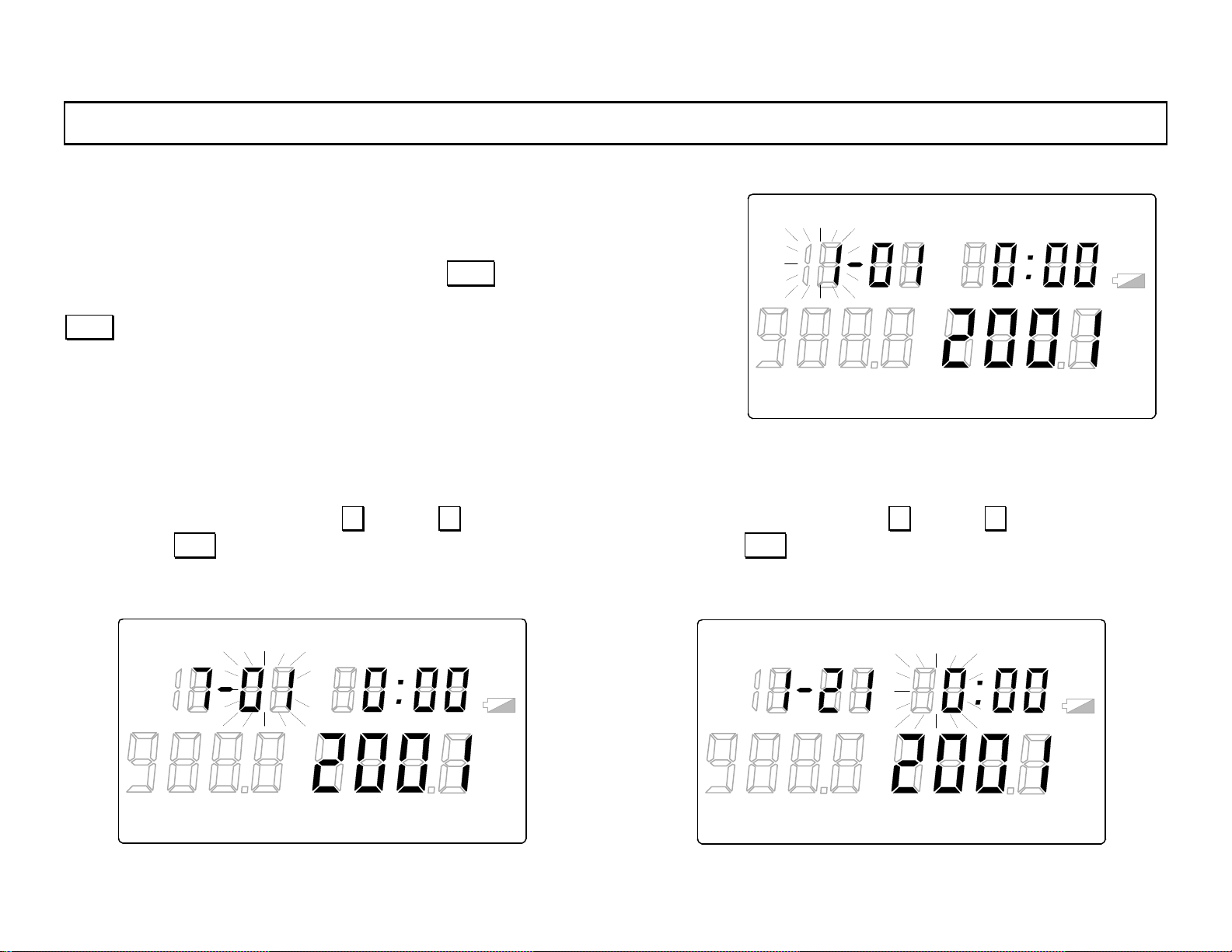
5.2.1 Clock adjustment mode
In the continuous measurement mode, press DISP key for 2 seconds to go
LOG TIME UNIT ALARM
READ
to the stored data reading mode with “READ” lit in the main marker. Press
DISP
key again several times to go to the clock adjustment mode. In the
clock adjustment mode, “TIME” will light in the main marker and “month”
will flash.
5.2.2 Retaining of month
Select the “month” by pressing ∧ key or ∨ key .
By pressing ENT key, the month selected will be retained
and “day” will flash.
LOG TIME UNIT ALARM
READ
°
F
℃
°FH
℃
%RH
5.2.3 Ret aining o f day
Select the “day” by pressing ∧ key or ∨ key .
By pressing ENT key, the day selected will be retained and
“hour” will flash.
H
°
F
℃
TERM
LOG TIME UNIT ALARM
READ
REP
°
F
INT REF
℃
LOCK
°FH
℃
%RH
H
°FH
℃
%RH
H
TERM
REP
INT REF
LOCK
-13-
TERM
REP
INT REF
LOCK
Page 22
INST.No.INE-418-1P1CE
5. Measurement preparation
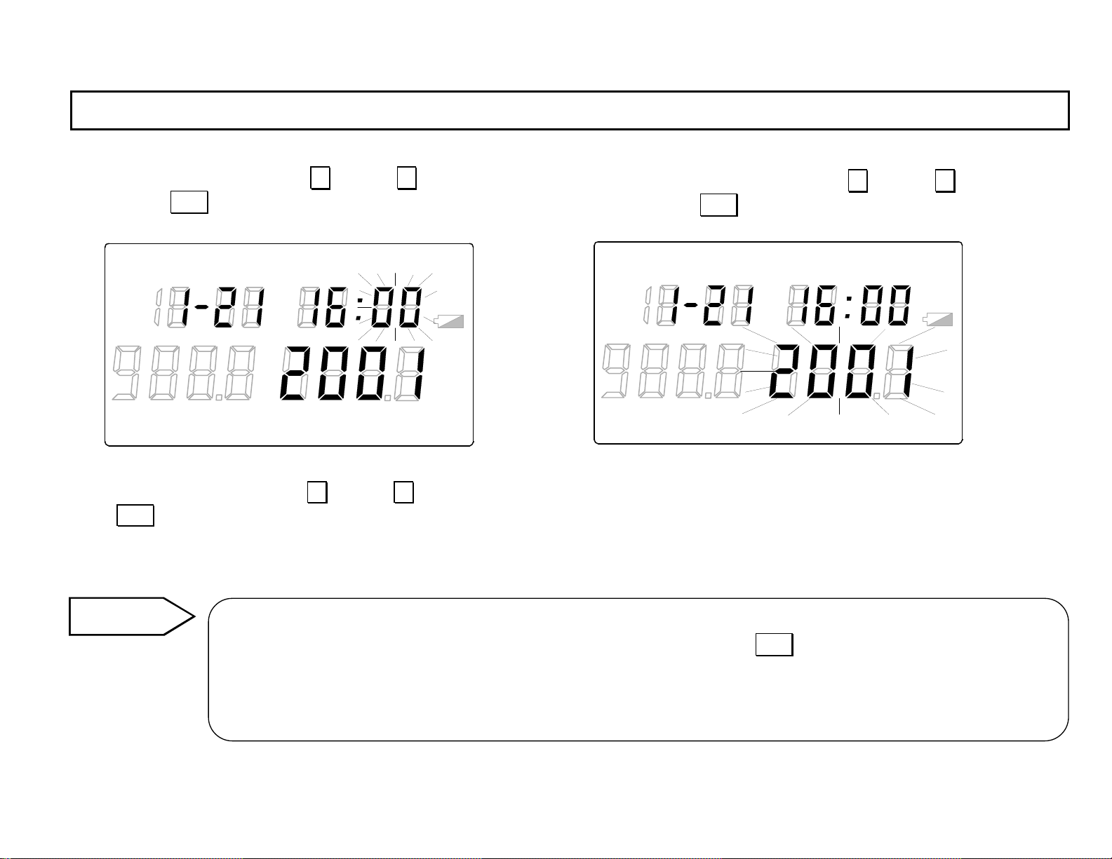
5.2.4 Retaining of hour
Select the “hour” by pressing ∧ key or ∨ key .
By pressing ENT key, the hour selected will be retained
and “minute” will flash.
LOG TIME UNIT ALARM
READ
5.2.5 Retaining of minute
Select the “minute” by pressing ∧ key or ∨ key.
By pressing ENT key, the minute selected will be
retained and “year” will flash.
LOG TIME UNIT ALARM
READ
°
F
℃
°FH
℃
%RH
H
TERM
REP
INT REF
LOCK
TERM
REP
5.2.6 Retaini ng of year
Select the “year ” by pressing ∧ key or ∨ key. (The year up to 2099 can be selected .)
Press ENT key to retain the year selected.
5.2.7 Storing of clock
°
F
℃
INT REF
%RH
LOCK
°FH
℃
H
The flashing of the year selected will stop and the clock programmed will be stored.
Reference
Judgment of clock
The judgment of the clock programmed is executed after pres sing
the date not existed (Ex. February 31) has been programmed, the screen will return to [5.2.2 Retaining of
month] screen with “month” flashing. Reprogram the correct date.
This judgment function supports leap years.
-14-
ENT key in [5.2.7 Storing of clock]. If
Page 23
INST.No.INE-418-1P1CE
g
5. Measurement preparation
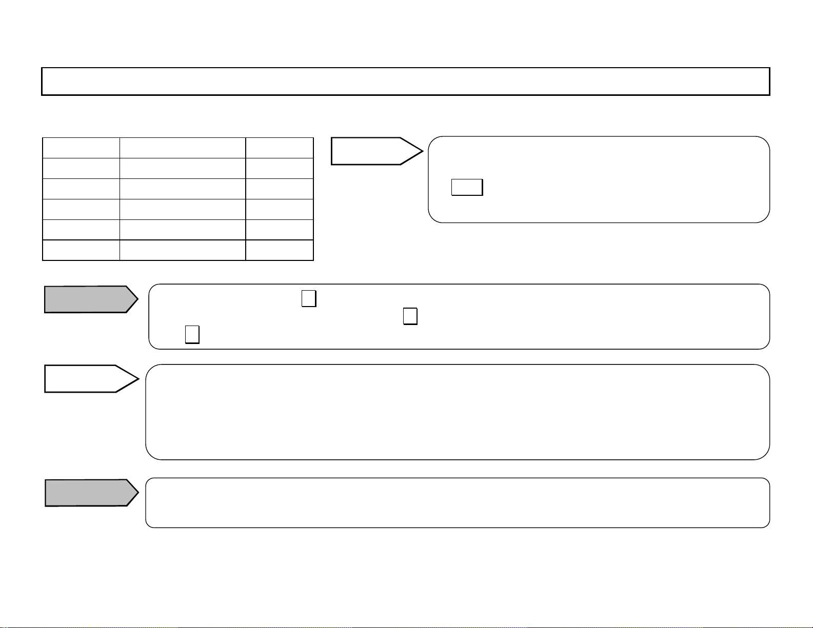
[Programming range of clock]
Programming range Default
Month * 1 to 12 1
Day * 01 to 31 01
Hour 0 to 23 0
Minute 00 to 59 00
Year 2001 to 2099 2001
Reference
* Leap years are supported.
Caution
Reference
For the programming by ∧ key , when the value reaches to the maximum value of the programming range,
it will not return to the default value even if ∧ key is pressed continuously.
Use ∨ key to decrease the value.
Accu rate clock programmin
For the accurate clock programming including second, take the following procedures.
1. Load the batteries at 0 second by referring to the radio time signal or an accurate watch.
2. Adjust the clock with the procedures from Para. 5.2.1 to Para. 5.2.7.
The counting of second starts at the moment the battery is loaded.
The time is based on 24-hour clock system. Program
14-hour for PM2 and 22-hour for PM10.
If
DISP key is pressed before the retaining of year, the
programmed data before it will not be stored.
Caution
The clock will be initialized when the batteries are replaced. Reprogram the clock.
If the clock is reprogrammed, all time-related-parameters will be initialized. Reprogram the parameters.
-15-
Page 24
INST.No.INE-418-1P1CE
5. Measurement preparation
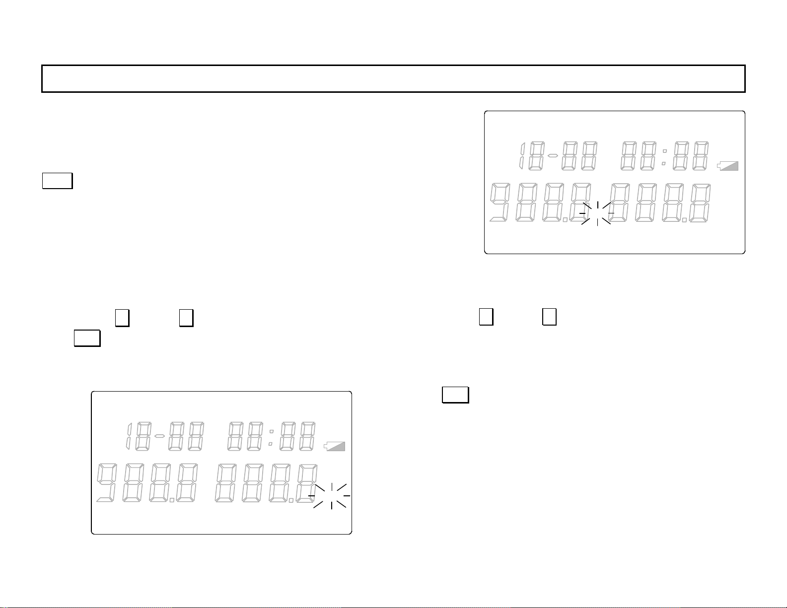
5.3 Measurement unit selection
5.3.1 Measuremen t unit selec tion mode
In the clock adjustment mode with “TIME” lit in the main marker, press
DISP
key several times to go to the measurement unit selection mode
(“UNIT” will light in the main marker.). In the measurement unit selection
mode, “
5.3.2 Temperature measurement unit
By pressing ∧ key or ∨ key, “ºC” or “ºF” will flash.
Press ENT key to retain the temperature measurement unit
selected. The te mp era tur e measurement unit selected will
stop flashing and the humidity measurement unit will flash.
ºC” will flash.
LOG TIME UNIT ALARM
READ
5.3.3 Humidity measurement uni t
By pressing ∧ key or ∨ key, “ºC” or “%RH” will flash
when “ºC” is selected in [5.3.2 Selection of temperature
measurement unit], or
is selected.
Press ENT key to retain the humidity measurement unit
selected. The humidity measurement unit selected will stop
flashing
°
F
℃
°FH
℃
%RH
H
TERM
REP
INT RE F
LOCK
LOG TIME UNIT ALARM
READ
°
F
℃
TERM
REP
INT REF
LOCK
“ºF” or “%RH” will flash when “ºF”
°FH
℃
%RH
H
-16-
Page 25
INST.No.INE-418-1P1CE
5. Measurement preparation
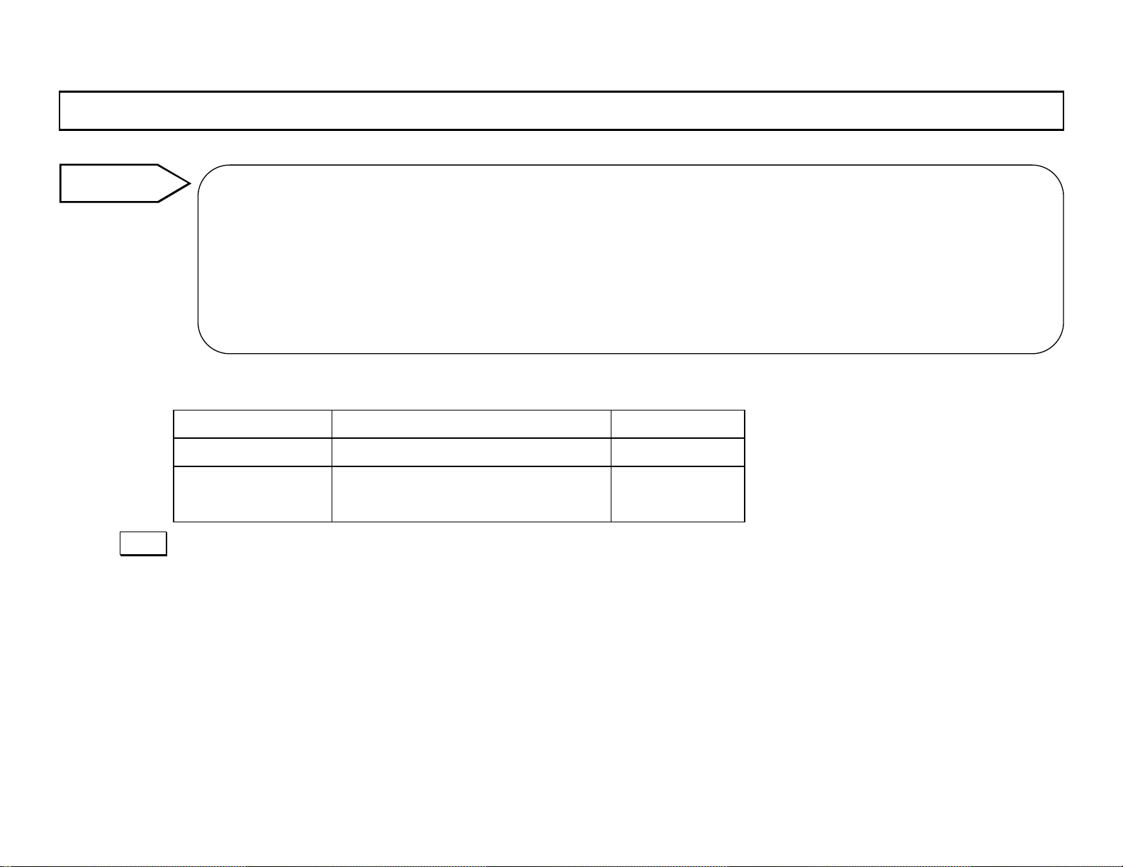
Reference
When the measurement unit is changed, the parameters of high alarm, low alar m and totalizing referen ce
temperature will be initialized.
When
from
the temperature measurement unit and the humidity measurement unit, when
temperature measurement unit, t he humidity measurement unit becomes
Selection Default
T em perature unit ºC, ºF
Humidity unit
DISP key for about 2 seconds to go to the continuous measurement mode (Ref. [6.1 Continuous measurement] for
Press
starting the measurement.
“°C” is selected for the temperature measurement unit, the humidity measurement unit is selected
“%RH” or “ºC”. When “ºF” is selected, it is selected from “% RH” or “ºF”. In condition that “ºC” is for
“ºF” is selected for the
“ºF” forcibly .
ºC
%RH (Relative humidity)
%RH
ºC, ºF (Dew-point tem perature)
-17-
Page 26
INST.No.INE-418-1P1CE
r
6. Continuous measurement
6.1 Continuous measurement mode
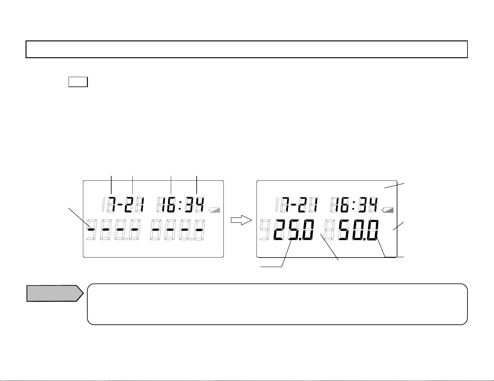
By pressing
DISP key, the temperature/humidity measurement will start after bars are displayed for about 1 second.
The measured temperature will be displayed in the main display 1 and the measured hu midity will be displayed in the main
display 2 together with the display of month, day, hour, and m inute at the measurement.
The temperature measurement unit and the humidity measurement unit being displayed are the units already selected.
For the selection of the measurement unit, refer to [5.3 Measurement unit selection].
If
“ALARM” lights in the main marker, the measurement value has exceeded a high alarm setpoi nt or a low alar m setpoint.
Check the setpoints and reprogram them if necessary. Refer to [4.2 High alarm setpoint] and [4.3 Low alarm setpoint] in
the separate instruction manual Vol. 2 <Function instructions>.
Bar
Month Day Hour Minute
LOG TIME UNIT ALA RM
TERM
READ
REP
°
F
℃
INT RE F
%RH
LOCK
°FH
℃
H
LOG TIME UNIT ALARM
READ
Main marke
Humidity
TERM
REP
°
F
℃
INT RE F
%RH
LOCK
°FH
℃
H
measurement
Main display 2:
Main display 1:
T emperature
T emperature
measurement unit
Humidity
Caution
If “Er4” for “low batter y” or “meter abnormal ” is displayed in the main display 2, replace the batteries
first. (Ref. [5.1 Loading of batteries] in the separated instruction manual Vol. 1 <Basic instructions>)
If
“Er4” is still displayed by the above repl acem ent of batterie s, c ontact your CHINO’s agent.
-18-
Page 27
INST.No.INE-418-1P1CE
(
6. Measureme nt and data storage
6.2 Measured temper ature/humidity displ ay range
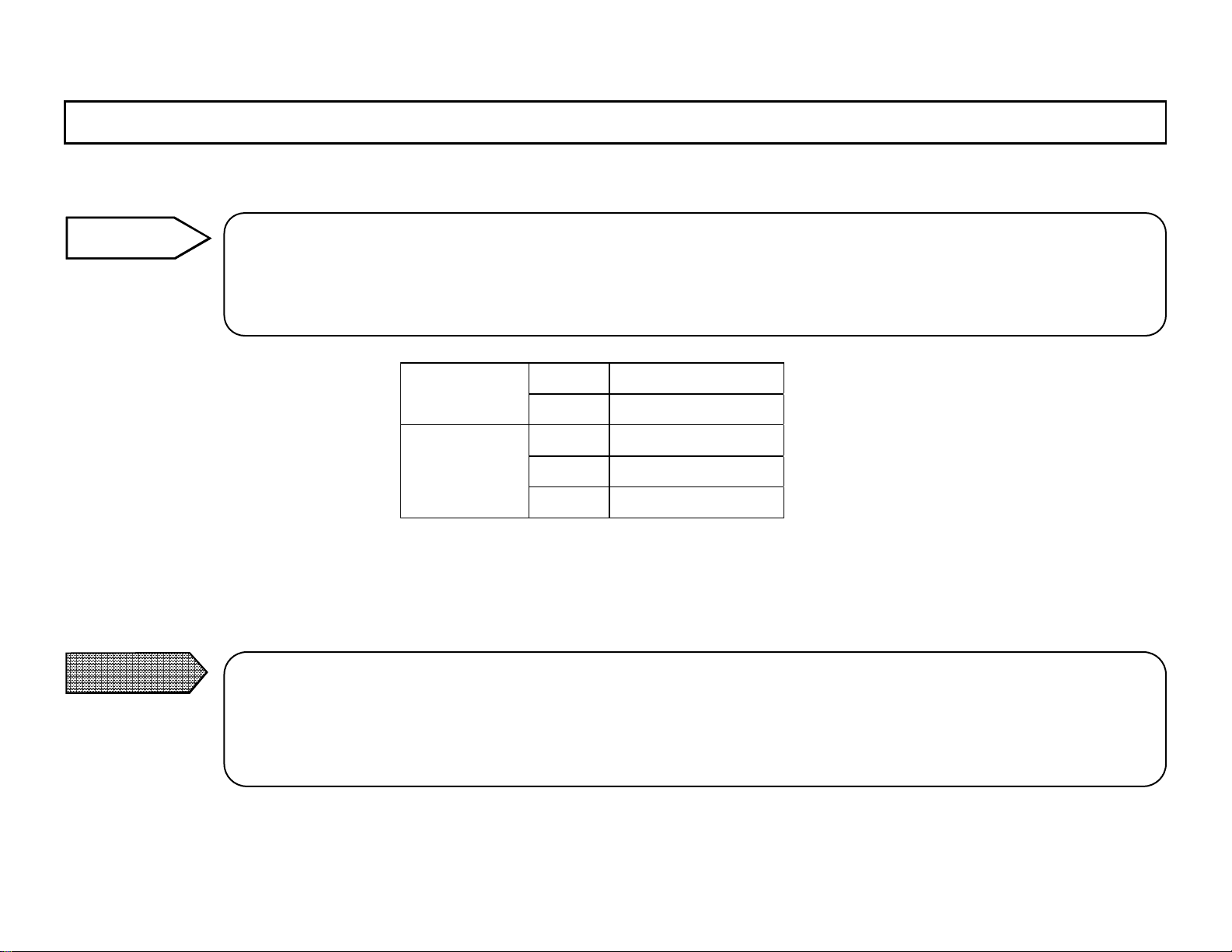
Reference
When the measured temperature is lower th an the minimum li mit, “uFL” will be displayed in the main
display 1 and, whe n it is higher than the maxim um limit,
When the measured humidity is 0%, 0% will be displayed, but when the measured humidity is higher than
100%
dew condensation), the value wil l be held a t 100%.
“oFL” wi ll be dis play ed.
ººC
ºF
Humidity
%RH
ºC
ºF
-40 to 80ºC T emperature
-40 to 176ºF
0 to 100%R H
-60 to 80ºC
-76 to 176ºF
When the clock is displayed after the measurement for about 1 minute, the auto-power-off function is “on” (active).
For continu ing the continuous measurement, select the auto-powe r-off function to
“oFF” (releas e) . (Ref . [ Aut o -po we r-off func ti on ] in
Important notices)
Caution
When the a uto-power-off function is set at “oFF” (release) and t h e continuous measurem ent is executed,
the batterie s will be consumed very rapidly.
For the continuous measurement constantly executed, use the AC power adapter (RH32-AC110) sold
separate ly.
-19-
Page 28
INST.No.INE-418-1P1CE
])
n
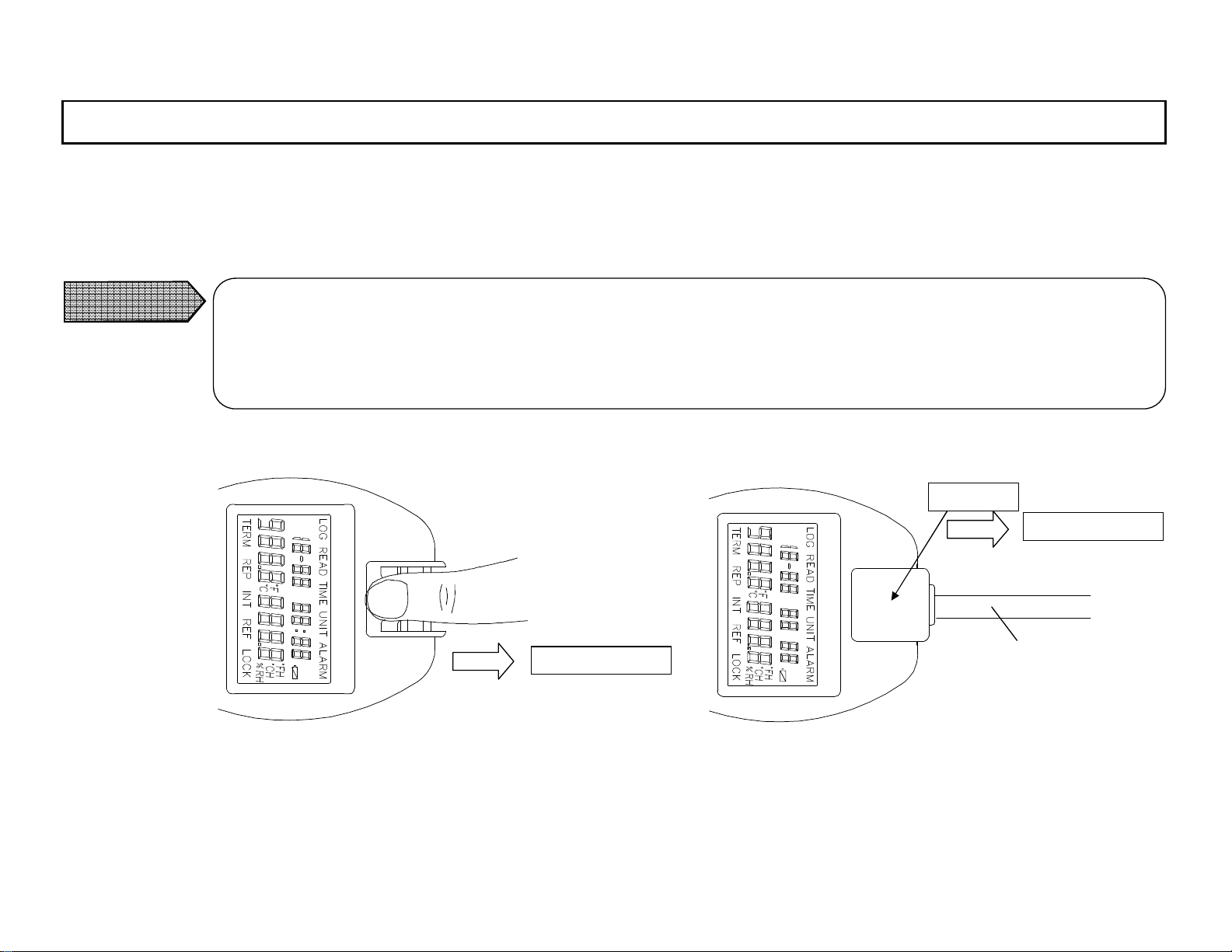
7. Replaceme nt of temperature/humidity sensor (Ref . [3.1 O ver vie ws and fu nct ions
The follow ing procedur e is for the replaceme nt of the tempe rature /humidity sensor bein g used for long period with a ne w one or
the re plac eme nt of the bui lt- in ty pe tem per atu re/h um idity se nsor w ith th e sep ara ted type se nso r or the probe ty pe sens or .
1) Pul l out th e temp era tur e/h umi dity sens or fr om thi s meter.
Caution
Make s ure to pull out th e temper atu re/humidi ty se nsor strai ght by hol ding its front and rear faces by two
fingers. Pins may be bended if it is not pulled out straight.
For discon necti ng the sepa rate d type sen sor or the pr obe ty pe sensor fr om this me ter , pul l out it by hol ding the
connection part. Make sure not to pull out the cable. (Ref. [1 1. External dimensions])
Connecti on part
Hold here.
Pull out s traig ht.
Pull out s traig ht.
(*) Do
Cab le (*)
’t pull out the cable.
<Built- in ty pe RH32B>
<Separated type RH32S>
<Probe ty pe RH32P>
-20-
Page 29
INST.No.INE-418-1P1CE
f
e
])
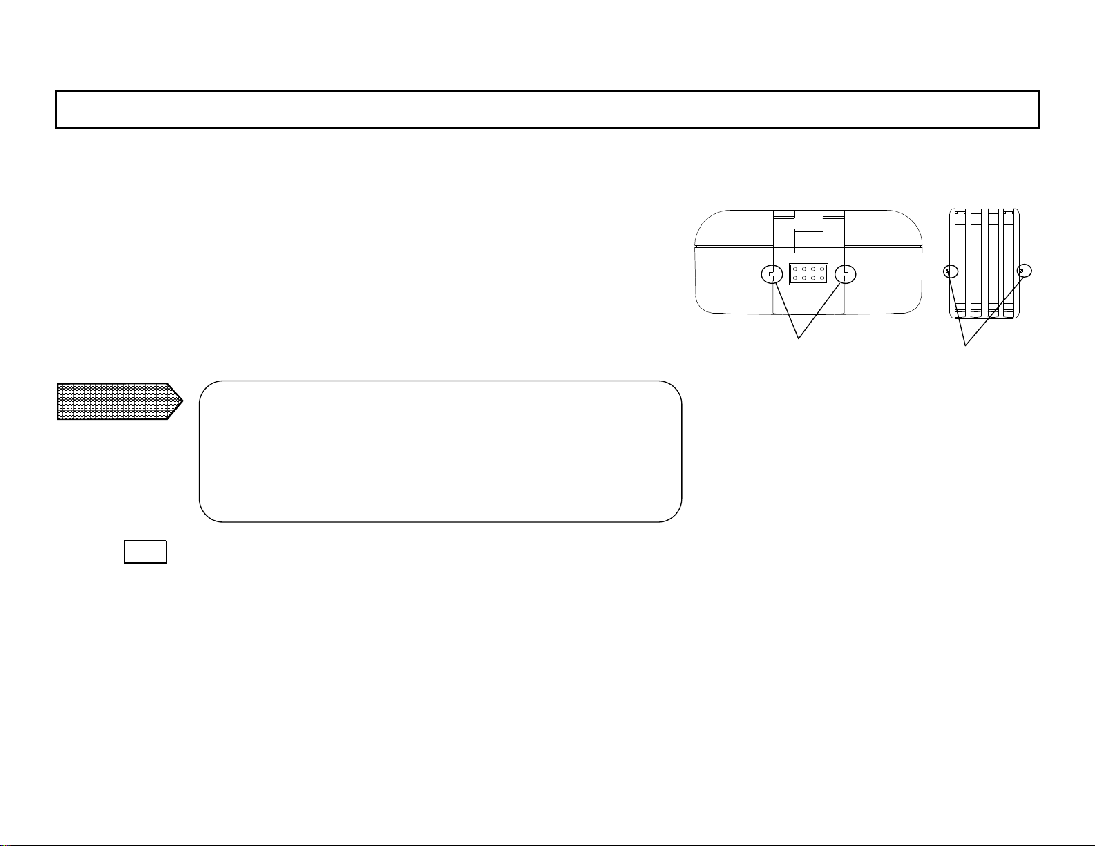
7. Replaceme nt of temperature/humidity sensor (Ref . [3.1 O ver vie ws and fu nct ions
2) Al ig n t h e pr ot rusi ons at both si de s o f th e conn ect ion p art of th e t emp er a<From to p>
ture/humidity sensor (RH32S
-RP and RH 32P-RP) or at both sides of the
built-in sensor (RH32B-RP) with the co ncave portions of th is meter, and
inse rt the c on nect io n part or the bu il t-in se nso r stra igh t.
3) Align the pins of the connection part or the built-in sensor with the
connec tor of th is meter, and push t he conn ecti on part or the bu ilt-in se nsor
into this me ter straight.
Caution
If you sq u eeze the connection part or the built -i n senso r into
this meter, the positions of the connector of this meter and
th e pins of t he co nnecti on p art o r the buil t-i n sens or ar e no t
fitted and the pins may be broken.
4) Press DISP key fo r ab out 2 seconds t o go to the contin uo us measurement
mode. At this time, the temperature and humidity values displayed are
differ ent f rom the e xac t measure d val ues.
Concave portions
of mete r
Protrusions o
built-in typ
sensor
-21-
Page 30
INST.No.INE-418-1P1CE
])
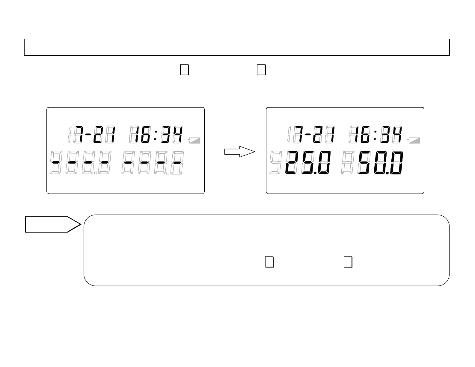
7. Replaceme nt of temperature/humidity sensor (Ref . [3.1 O ver vie ws and fu nct ions
5) In the continuous measurement mode, press ∨ key whil e press ing ∧ (SHIFT) key.
After bars are dis playe d for abou t 1 second, the corre ct temper ature and hum idity me asured values will be display ed.
TERM
Reference
READLO G TIME UNIT ALARM
°FH
°
REP
F
℃
IN T RE F
LOC K
℃
%RH
H
In terc han ge ab i lity of tem per a tur e/ hum id i ty sens or s
The temperature/humidity sensors, the built-in type (
probe ty pe (
RH32 P - R P), are interchangeable.
The interchangeabilit y will be obtai ned by press ing
dure No. 5)
READLOG TIME UNIT ALARM
°FH
°
TERM
REP
F
℃
INT REF
LOC K
℃
%RH
H
RH32B-R P), the separated type (RH32S - RP) and the
∨ key whil e pressi ng ∧ (SHIFT) key in the proce-
-22-
Page 31
INST.No.INE-418-1P1CE
8. Working environment
A void to use this meter in the following places.
Places where the ambient temperature is out of –10 to 50ºC (this meter)
Places where the ambient temperature is out of –40 to 80ºC (separated type and probe type sensors)
Places where dew condenses
Places where vibration or impact affects
Places where much noise ex ist
Places where dusts exist
Places where mu ch ketones organic solvent, esters organic so lv ent, halogen, strong acid material, corrosive materi al or
dus t/o il m is t/s a lt m is t exi st
Places where explosive gas, corrosive gas or flammable gas exist
Places where steam, chemicals or seawater splash
Caution
As the humidity element is constantly exposed in ambient atmosphere, its perfo rmance may be r emarkably
deteriorated depending on measuring environment.
Its life depends on the kind of environment. Particularly avoid using it in the following places as these places
make the humidity element life shorten rap idly.
Place where ketones organic solvent, esters organic solvent, halogen, strong acid material, corrosive mate-
rial, dust /o il mis t/sa lt mi st, c orro siv e gas , ste am or sea wat er sp la shin g exi st.
-23-
Page 32
INST.No.INE-418-1P1CE
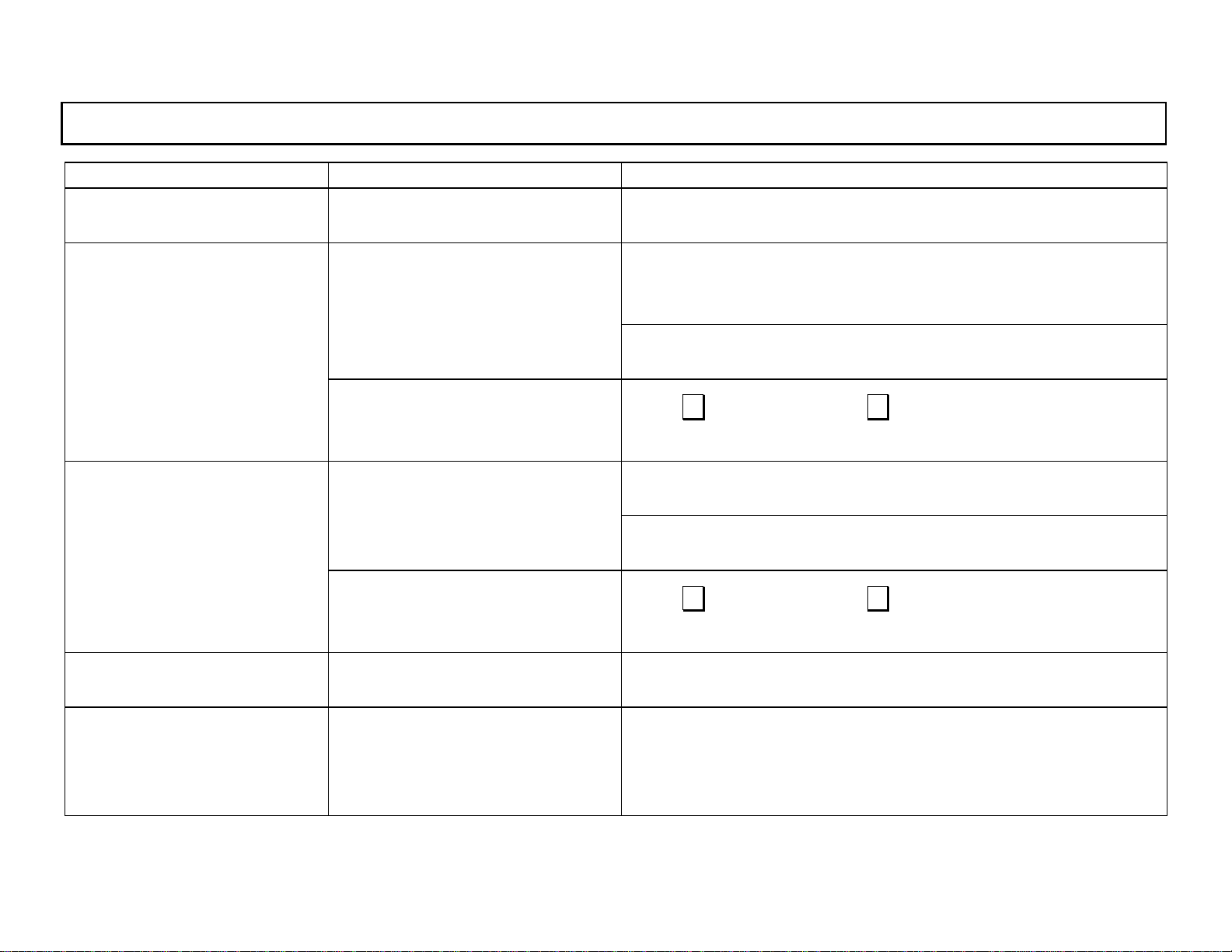
9. Troubleshooting
Phenomenon Content Countermeasure
1) “Er1” is displayed in the
main display 1.
2) The humidity value in the
main display 2 is 100%RH
(Th e dew-poin t temper ature
display becomes the same
value as t he t emper ature
measured value.).
3) The humidity value in the
main display 2 is 0%RH
(The dew-point temperature
display becomes -60ºC .).
Temperature meas uremen t can’t be
executed .
100% RH has been mea su red i n the
humidity mea s u remen t.
Interchangeability of the temperature/humidity sensor has not been
obt ained.
0%RH has been measured in the
humidity mea s u remen t.
Interchangeability of the temperature/humidity sensor h as not b een
obt ained.
Check the co nnec tion of t he temp eratur e/humi dity se nsor .
(Ref. [7. R eplacem ent of tempe rature /humi dity sensor])
Check if dew has been condensed in the temperature/humidity
sensor .
Measurement is possible after recovering from dew condensation.
Check the co nnec tion of t he temp eratur e/humi dity se nsor .
(Ref. [7. R eplacem ent of tempe rature /humi dity sensor])
Press ∨ key while pressing ∧ key .
(Ref. [7. R eplacem ent of tempe rature /humi dity sensor])
Th e humidity measur emen t f r o m 0% RH is possible.
Check if an object i s not i n absolut e dry condi tion .
Check the co nnec tion of t he temp eratur e/humi dity se nsor .
(Ref. [7. Re placem ent of tempe rature /humi dity sensor])
Press ∨ key while pressing ∧ key.
(Ref. [7. R eplacem ent of tempe rature /humi dity sensor])
4) “Er1” is displayed in the
main display 2.
5) “Er2” is displayed in the
main display 2.
Humidity measurement can’ t be
executed .
In the dew-point temperature displa y, the dew-p oint co mputat ion is
not possible due to abnormal
temperature da ta.
-24-
Check the co nnec tion of t he temp eratur e/humi dity se nsor .
(Ref. [7. R eplacem ent of tempe rature /humi dity sensor])
If “E r1” i s displayed in the main display 1, check the connection of
the temperature/humidity sensor .
(Ref. [7. Re placem ent of tempe rature /humi dity sensor])
Page 33
INST.No.INE-418-1P1CE
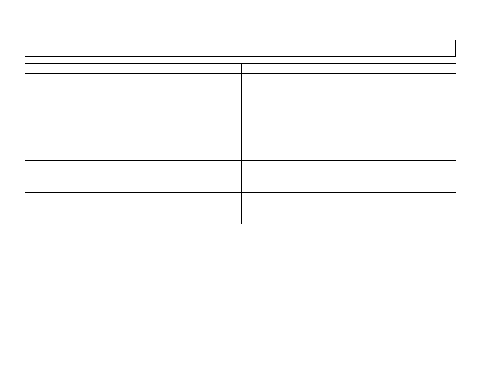
9. Troublesho oting
Phenomenon Content Countermeasure
The batterie s are d ead.
6) “Er4” is displayed in the
main display. 2
7) Nothing inc lud ing the clock
is displayed.
8) None displayed The batteries are dead
9) “oFL” is displayed in the
main di sp l ay 1.
10) “uFL” is displayed in the
main display 1.
If “Er4” is st ill disp la yed a fter th e
battery replacement, this meter has
be en ab normal.
No power has been supplied.
Temperature m eas ured value
ove rf lowed
Temperature measured value under
flowed
Replace t he batt eries wi th n ew ones. (R ef . [5.1 Loading of batte rie s])
If “Er4” is still displayed after the battery replacement, contact your
OM EGA’ s agent .
Replace t he batt eries wi th new on es.
(Ref. [5 .1 Loading of batt eries])
Replace t he batt eries wi th new on es.
(Ref. [5 .1 Loa ding of ba tterie s] )
Check the tem perat ure me asuring r ange.
Check the co nnec tion of th e tempera ture/humi dity sensor.
(Ref. [7. R eplac ement of tempe rature /humi dity sensor])
Check the tem perat ure me asuring r ange.
Check the co nnec tion of th e tempera ture/humi dity sensor.
(Ref. [7. R eplacem ent of tempe rature /humi dity sensor])
-25-
Page 34
INST.No.INE-418-1P1CE
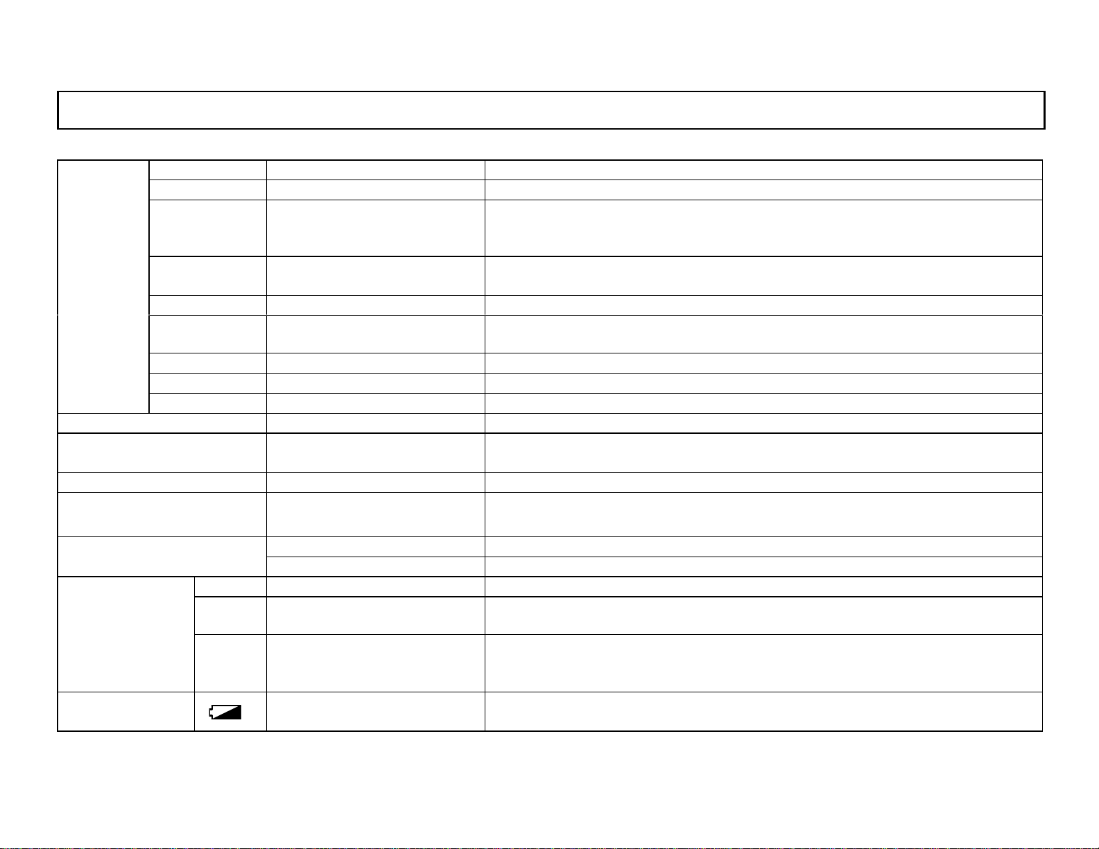
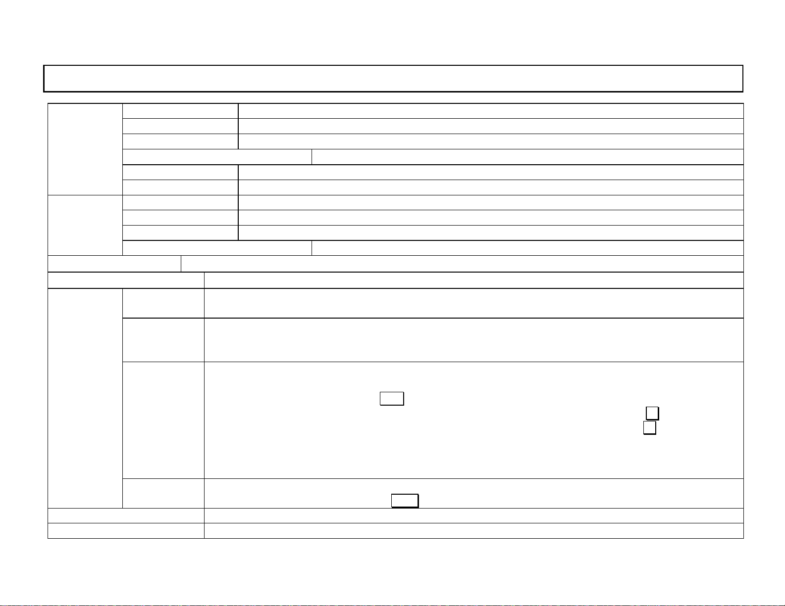
10. Specifications
Sensor High-polymer capacitance ty pe
Me as uri ng ra ng e 0 to 1 0 0%RH
Relative
humid i ty
T emperature
Sensor interchangeability
Power supply
Display
Number of stored data T emperature/humidity – each maximum 8000 data, total 16000 data EEPROM)
Comm u ni ca t i ons func tio n RS- 232 C or R S - 485
Accuracy ra tings ±2%RH ( 0 to 9 0%RH,at 25ºC), ±3%RH (90 to 95%RH, at 25ºC)
Stability ( under EMC tes t environme nt) ±3%RH
T emperature coefficient ±0.1%RH/ºC (5 to 80ºC)
Response time Shorter than 15 seconds (90% r esp onse, 2 5ºC const a nt , un de r 0. 1m/ s v e nt ilation)
Sensor Semi- c on duc t or type te m per a t ure s ensor
Me as uri ng ra ng e -10 to 50ºC, - 40 to 8 0ºC (Pr o be type RH 32P, sepa r a ted ty pe RH32S)
Accuracy ratings ±0.5ºC (0 to 50ºC), ±1ºC (other than the left shown)
Stability ( under EM C test env ironme nt) ±0.5%RH
Plug-in ty pe interchang eability (Plug-in ty pe inte rchangeability incl uding 1. 5m cable f or probe type and sepa rated ty pe sens or)
2 A A (UM- 3) al kal ine bat ter ie s or 10 0VAC (A C powe r ada pt er – s old sepa r at ely )
Current data
Data reading
Parameter item
Display co ntent
Year, month, day, hour, minut e , t e m pe ra t ure m e asured v al ue (ºC or ºF),
Relative humidity or dew-p oint tem perature meas ure d value (ºC or ºF)
Progr ammed p aramet e r s, stored data w ith ye a r, mo nt h, day, hour, an d minute (The year da t a is avai l able in u sing the da ta
logging software package (sold separately).
Max. temp./humidity, min. tem p./humidity, average temp./ humidity, totalized temperature
Clock : Year , mont h, day, hour , mi nute , Tempera ture : ºC, ºF
Relative humidity, dew-point temperat ure (ºC or ºF )
Stor ag e m o de: M a nual [by pre s s ing of ENT (LO G) key for more than2 se conds] or automatic
Stor ag e s t ar t ti m e: Year , month, day, hour, m in ute , or by press i ng of ENT ( L OG) k ey w hi le pr es sing ∧ (SHIFT) key
Stor ag e s t op t im e : Year, mon th, day, hour, mi n ute or by press ing of E NT (L O G) k ey while pr e ss ing ∧ (SHIFT) key
Storage repetition: Disable, every day, every week
Mea sur eme nt i nter va l: c onti nu ous, 1 t o 60 mi nute s
High/low alarms, t otalizing re fere nce te mperat ure, totalizing dir ecti on, aut o-power -off , key lock
Clock – dis pl ay ed co nst a ntly
Mea sur e d v al u es – display ed by pre s s ing DISP key for about 2 sec onds in power-off condition
-26-
Page 35
INST.No.INE-418-1P1CE
p
r
r
k
1 1. External dimensi ons
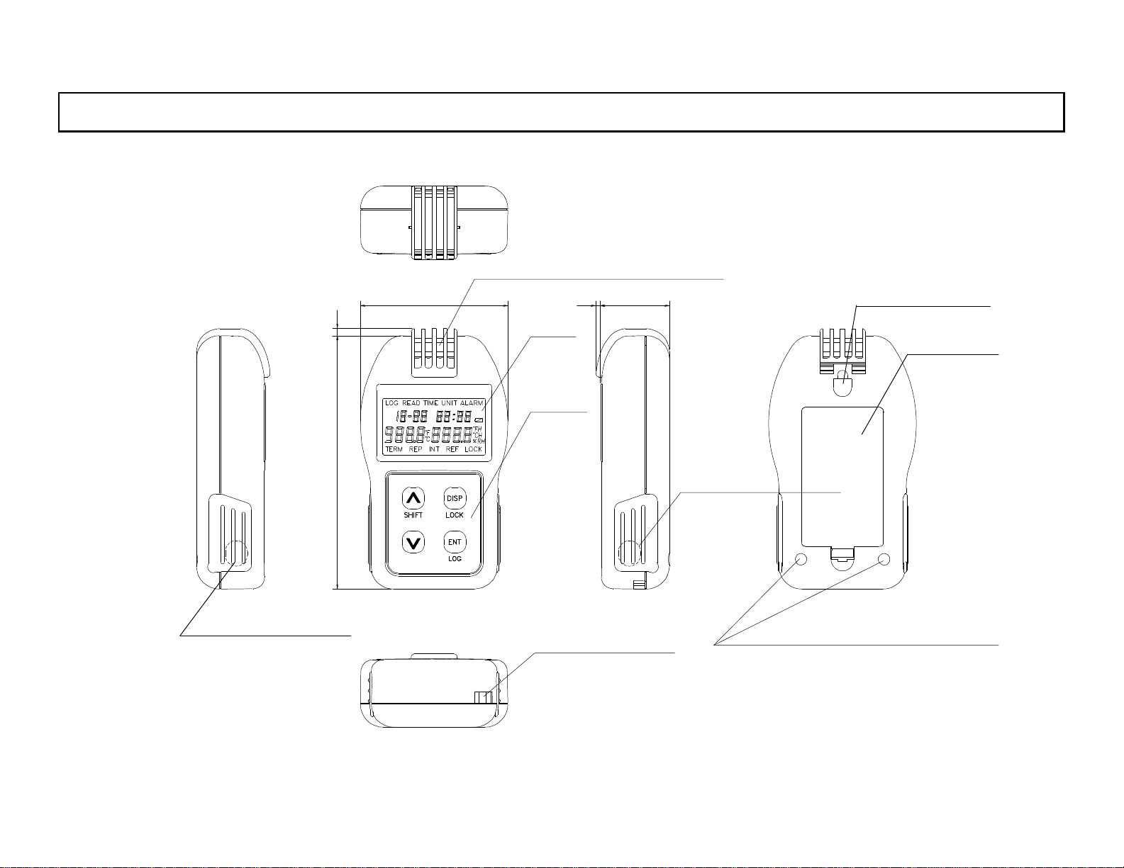
11.1 External dimensions of RH32B-C
3
64
Tem
erature / humid ity sen so
2
30
Disp la y
Function
key
Hole for wall
ins tallatio n
Battery cover
110
Comm un icati o ns jac
Cove r for AC p ow e
adapter jack
Hole for strap
Hole s for d esk top a tta chme nt
unit : mm
-27-
Page 36
INST.No.INE-418-1P1CE
1 1. Ex ternal di mensions
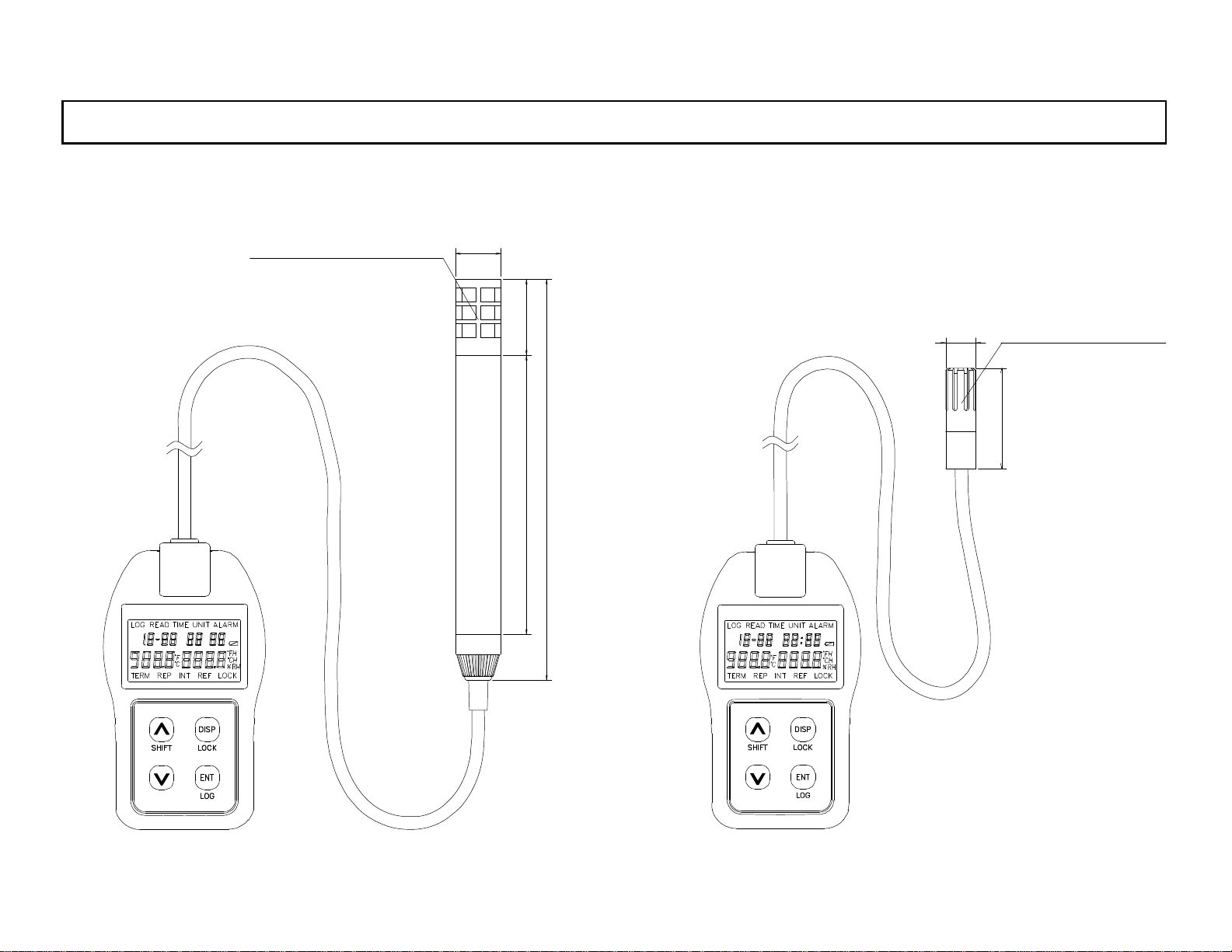
11.2 External dimensions of RH32P-C 11.3 External dimensions of RH32S-C
T emperature
/ hum i di ty sens or
φ18
Cabl e le ng th: 1. 5m
Cable length: 1.5m
φ12
T emperature
/ hum id i ty sen s or
40
158
110 30
unit : mm
-28-
 Loading...