

Page 1

omega.com
e-mail: [email protected]
For latest product manuals:
omegamanual.info
User’s Guide
RH318
Data Logger
Hygro-Thermometer
Shop online at
MADE IN TAIWAN
Page 2

Servicing North America:
U.S.A.: Omega Engineering, Inc., One Omega Drive, P.O. Box 4047
ISO 9001 Certified Stamford, CT 06907-0047 USA
Canada: 976 Bergar
Laval (Quebec), H7L 5A1 Canada
Toll-Free: 1-800-826-6342 TEL: (514) 856-6928
FAX: (514) 856-6886 e-mail: [email protected]
For immediate technical or application assistance:
U.S.A. and Canada: Sales Service: 1-800-826-6342/1-800-TC-OMEGA
®
Customer Service: 1-800-622-2378/1-800-622-BEST
®
Engineering Service: 1-800-872-9436/1-800-USA-WHEN
®
Mexico/ En Español: 001 (203) 359-7803 FAX: 001 (203) 359-7807
Latin America [email protected] e-mail: [email protected]
Servicing Europe:
Benelux: Managed by the United Kingdom Office
Czech Republic: Frystatska 184
733 01 Karviná, Czech Republic
Toll-Free: 0800-1-66342 TEL: +420-59-6311899
FAX: +420-59-6311114 e-mail: [email protected]
France: Managed by the United Kingdom Office
Toll-Free: 0800 466 342 TEL: +33 (0) 161 37 29 00
FAX: +33 (0) 130 57 54 27 e-mail: [email protected]
Germany/Austria: Daimlerstrasse 26
D-75392 Deckenpfronn, Germany
Toll-Free: 0800 6397678 TEL: +49 (0) 7056 9398-0
FAX: +49 (0) 7056 9398-29 e-mail: [email protected]
United Kingdom: OMEGA Engineering Ltd.
ISO 9001 Certified One Omega Drive, River Bend Technology Centre, Northbank
Irlam, Manchester M44 5BD United Kingdom
Toll-Free: 0800-488-488 TEL: +44 (0) 161 777-6611
FAX: +44 (0) 161 777-6622 e-mail: [email protected]
OMEGAnet®Online Service Internet e-mail
omega.com [email protected]
It is the policy of OMEGA Engineering, Inc. to comply with all worldwide safety and EMC/EMI
regulations that apply. OMEGA is constantly pursuing certification of its products to the European New
Approach Directives. OMEGA will add the CE mark to every appropriate device upon certification.
The information contained in this document is believed to be correct, but OMEGA accepts no liability for any
errors it contains, and reserves the right to alter specifications without notice.
WARNING: These products are not designed for use in, and should not be used for, human applications.
Page 3

TABLE OF CONTENT
1. SAFETY INFORMATION............................................................................................................................... 1
2. GENERAL DESCRIPTION ............................................................................................................................ 1
3. FEATURE ...................................................................................................................................................... 1
4. SPECIFICATIONS ......................................................................................................................................... 1
5. BUTTONS AND FUNCTIONS ....................................................................................................................... 3
6. DATA LOGGER ............................................................................................................................................. 5
7. SETTING DATE AND TIME .......................................................................................................................... 6
8. POWER PREPARATION .............................................................................................................................. 7
9. TESTLINK SE-318 SOFTWARE FOR RH318 .............................................................................................. 7
Page i
Page 4

1. S AFETY INFORM ATION
Read the following safety information carefully before attempting to operate or service the meter. Use the
meter only as specified in this manual; otherwise the protections provided by the meter may be impaired.
ENVI RONMENT CONDITIO NS
Altitude up to 2000 meters
Relatively humidity: 90% max
Operation ambient temperature: 0 to 40°C
MAINTENANC E & CLEARING
Periodically wipe the case with a dry cloth. Do not use abrasives or solvents on this inst
S
AFETY SYMBOLS
Comply with EMC
rument.
2. G ENERAL DE S C RIPTION
Thank you for choosing our Data Logger Hygro-thermometer. To ensure the safety and the best performance
of this instrument, we recommend you to read and follow the manual carefully before any operation.
Measurement settings and results are shown on the backlit LCD panel.
Data can be stored in the meter or directly saved on a computer through PC interface. Recorded data can be
further processed on a computer.
3. F E ATURE
Interchangeable digital probes
Thermistor sensor for temperature measurement, fast response time
Dual display
Dew point measurement
16,000 Records Data Logger
PC Interface
With Windows software
Auto power off for battery saving
4. S PECIFICATI O NS
Sensor type
Relative humidity range
Temperature range
Dew point temperature range
Resolution
Electronic capacitance polymer film sensor / NTC
0 to 100%RH
- 20 to 60°C (- 4 to 140°F)
- 20 to 60°C (- 4 to 140°F)
0.1%RH, 0.1°C, 0.1°F
Page 1
Page 5

Accuracy Probe: RP-32
<10%RH, >90%RH ±4.0%RH
10%RH to 90%RH ±2.0%RH
-20 to 60°C (-4 to 140°F) ±0.8°C (±1.5°F)
Probe: RP-31
<10%RH, >90%RH ±5.0%RH
10%RH to 90%RH ±3.0%RH
-15 to 35°C (-60 to 95°F) ±0.8°C (±1.5°F)
<15°C (60°F), >35°C (95°F) See figure below
Response time
Sensor hysteresis
Temperature coefficient
Sample rate
Battery type
Battery lifetime
Ac adapter
Operation temperature
Operation humidity
Storage temperature
Storage humidity
Dimensions
Weight
(@ t90; in slowly moving air)
Humidity: 180 sec.
Temperature: 10 sec.
<1.5%RH
0.1 x (specified accuracy) per 1°C (<23°C or >23°C)
2 times per second
9V Battery
Approx. 80 hours (alkaline battery)
9 V
( 8-10VDC Max )
DC
0 to 40°C (32 to 104°F)
10 to 90%RH
-10 to 60°C (14 to 140°F)
10 to 75%RH
Meter: 185mm(L) × 65mm(W) × 36mm(H)
Probe: 15mm Diameter x 94mm(L)
Approx. 285g
Standard Accessories
Optional Accessory
Instruction manual, 9V Battery, windows software, carrying case,
USB cable
AC adapter
Page 2
Page 6
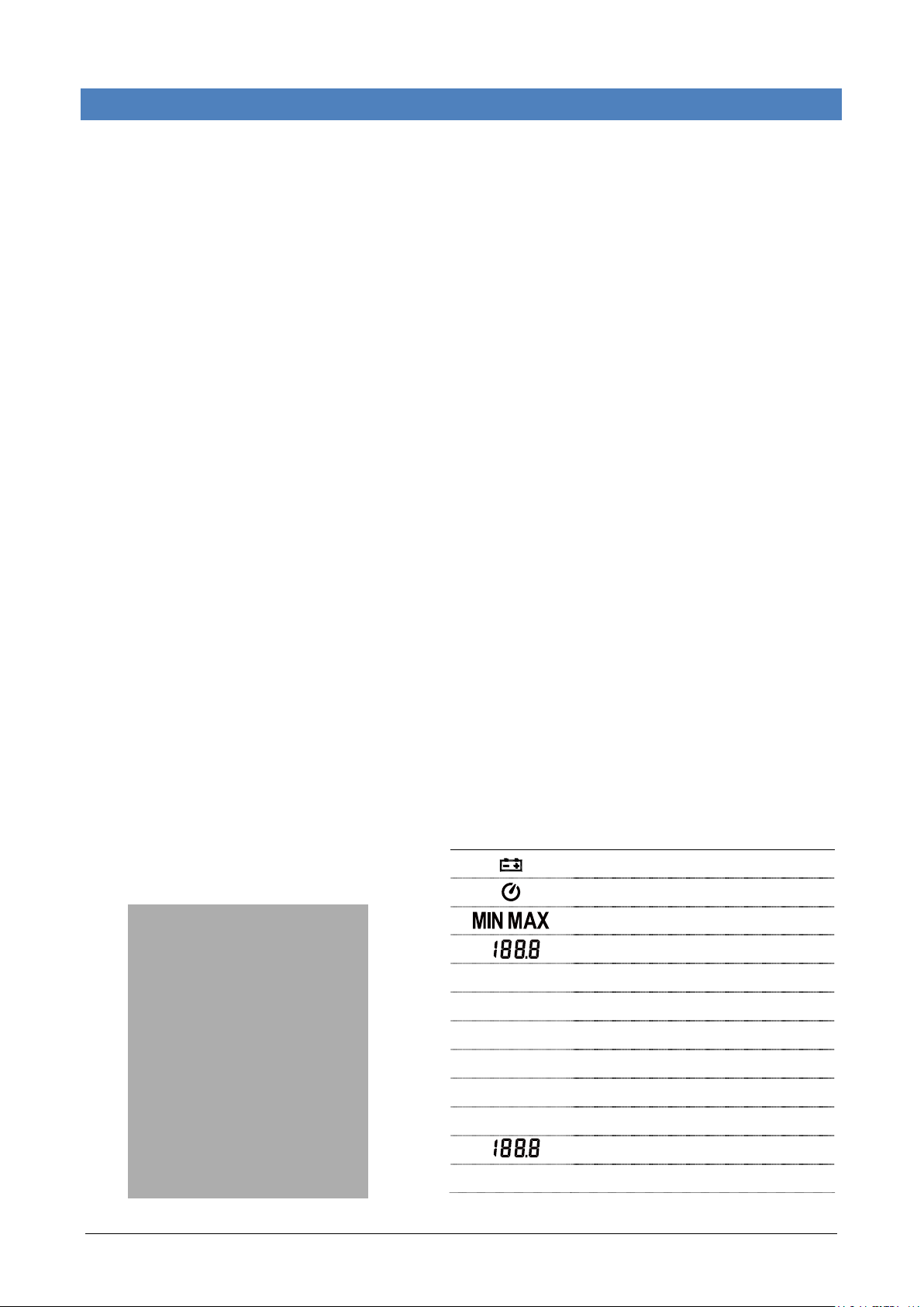
5. BUTTONS AN D FUNCTIONS
BUTTON ALLOCATIO N
DISPLAY SCREEN
SYMBOL FUNCTION
%RH
REC
td
HOLD
m-d
h:m
°F, °C
Low battery indicator
Auto power off indicator
Maximum/minimum indicator
Relative Humidity reading
Relative humidity measurement unit
Recording data logger indicator
Dew point temperature
Data hold indication
Month-day
Hour: minute
Temperature reading
Temperature measurement units
Page 3
Page 7
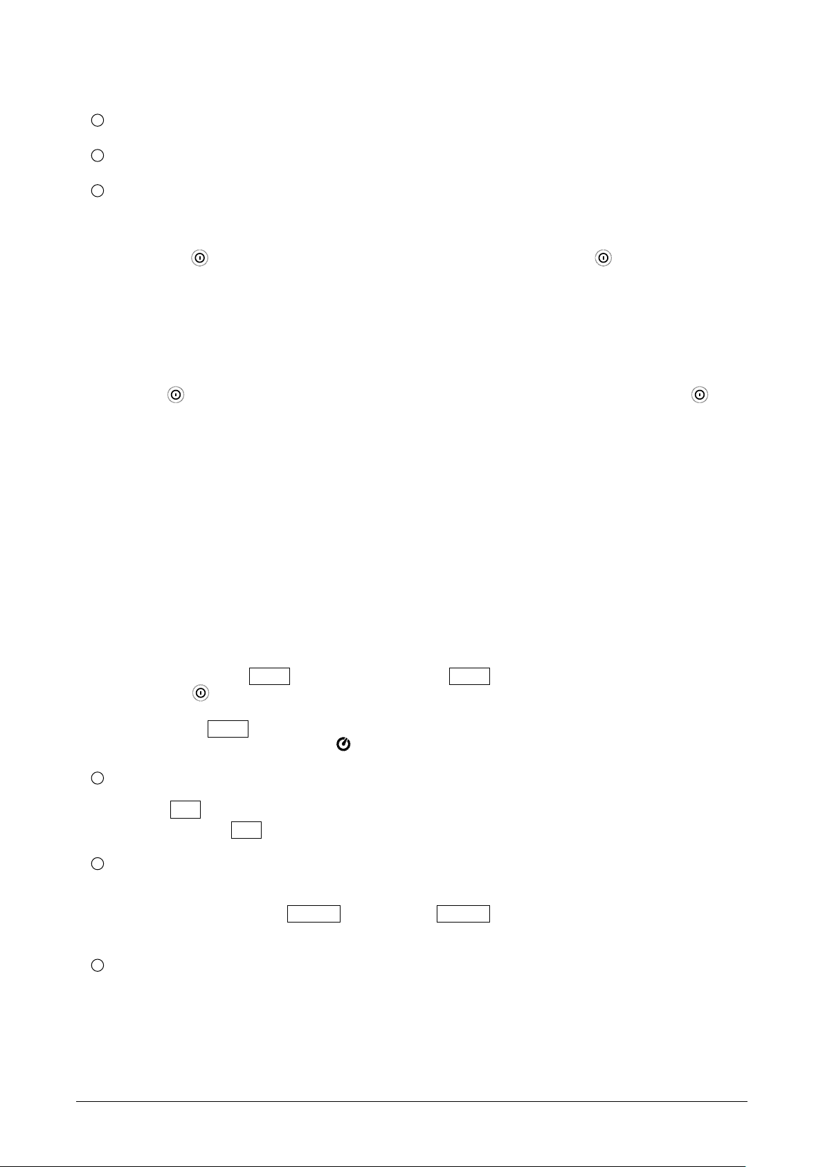
FUNCTIONS
1
Sensor probe
2
Display screen
3
Power / Backlight button
Power on/off
Press the
button to turn on the unit. To turn the unit off, press and hold button down until the
screen shows “OFF 3, 2, 1, 0,” then the LCD screen goes off.
Note: When the unit is on, the LCD will show the following initial information before entering the main
function: Available memory
Current date Current time Entering main function
LCD backlight on/off
Press
to turn on the LCD backlight, making it easier to read in dark environment. Press again
to turn off backlight. The backlight will turn itself off automatically after 30 seconds to save battery
power.
Auto power off
To save battery life, by default, every time the unit is powered on, it is under auto power off mode.
The unit will power itself off after 30 minutes if no key operation.
Auto power off will be automatically disabled under the following 2 circumstances:
When connecting to PC
When data logger function is on process
Disabled auto
(
1) Turn off the unit.
power off
(2) Press and hold HOLD button, and keep holding HOLD button.
(3) Press to turn on the unit.
(4) The LCD shows the initial information and then enter main function.
(5) Release HOLD button.
(6) Make sure the auto power off symbol disappears from display screen.
4
REC button
Press REC button to start recording data. The REC symbol will display on the screen. To stop
recording, press REC button again.
5
Relative Humidity/Dew Point Temperature switch
By default, the LCD displays Relative Humidity when the unit is powered on. To display dew point
(DP) temperature, press td %RH button. Press td %RH button again to switch back to Relative
Humidity.
6
MAX/MIN mode
Under this mode, the unit simultaneously monitors and stores the maximum and minimum value
(both humidity and temperature) in the memory. The unit will keep updating/refreshing the data.
To start
Page 4
Page 8
(1) Press MAX/MIX button. MAX symbol lights up on LCD, the reading shows the maximum data.
(2) Press MAX/MIX button again to show minimum data; the MIN symbol lights up on LCD.
(3) Press MAX/MIX button again, the MAX and MIN symbol blinks together. The reading shows
present humidity and temperature.
(4) Press MAX/MIX button again, MAX symbol lights up, and the mode returns to (1).
To exit
Press and hold MAX/MIX button for 2 seconds to stop storing maximum and minimum data.
Note: When the unit is in the MAX/MIN mode, °C/°F button is disabled.
7
Data-Hold mode
Press HOLD button to freeze the data shows on the LCD screen. Press again to exit Data-Hold
mode.
Note: When the unit is in the Data-Hold mode, the MAX/MIN, °C/°F, and td %RH buttons are
disabled.
8
Selecting temperature units
By default, each time the unit is powered on, the scale is set to the Celsius (°C). Press the °C/°F
button to switch between Celsius (°C) and Fahrenheit (°F).
9
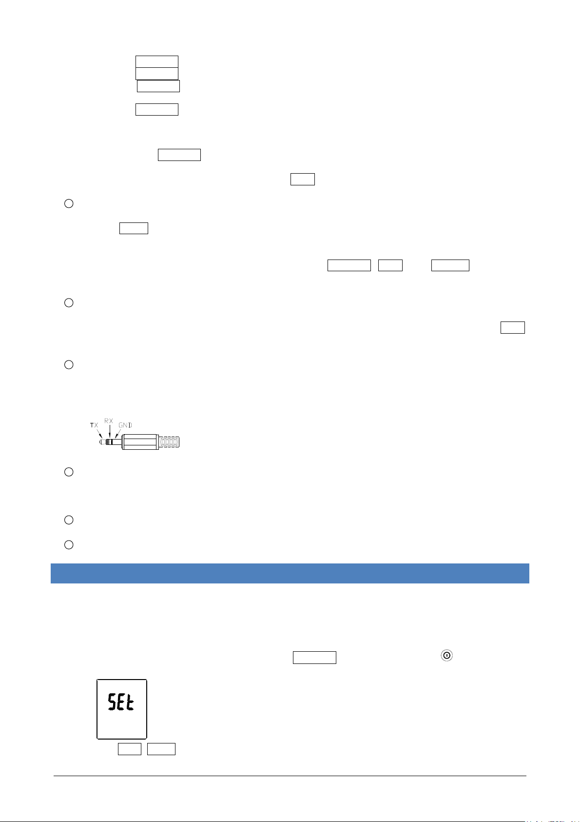
Connecting to a computer
The PC jack signal output is a 9600 bps N 8 1 serial interface. Use the USB cable (standard
accessory) to connect with a computer.
10
External DC 9V power supply jack
Connect the AC adapter (optional accessory) to use external power.
11
Tilt stand
12
Battery Compartment
6. D ATA LOG G ER
This section will explain how to store data (data logger) in memory and how to recall data from memory.
SETTING INTERVAL TIM E FOR DATA STORING
(1) Turn off the unit.
(2) Enter SETUP mode by pressing and holding MIN/MAX button and then press
turn on the unit. “SEt” blinks on the LCD screen.
power button to
(3) Press INTV (HOLD) button to set interval time.
Page 5
Page 9
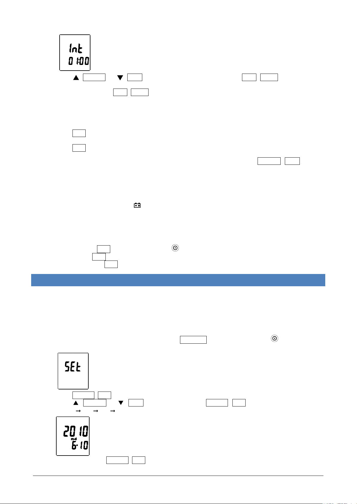
(4) Press (td %RH) or (°C/°F) to adjust the interval minute, press INTV (HOLD) button again to
adjust second.
(5) When finished, press INTV (HOLD) button to exit SETUP mode.
Note: To abort during the process, press power button to exit SETUP mode.
ST ART D ATA LOGGE R (STOR ING DATA IN THE MEMORY )
(1) Press REC button to start data logger (storing the measured values in built-in memory).
(2) REC symbol lights up on LCD screen.
(3) Press REC button again to stop recording.
Note: During recording period, most of the buttons are disabled, such as the td %RH, °C/°F, etc. All
other settings must be made before starting the data logger function.
Note: When the memory is full (16000 recorders), REC symbol will blink on the LCD screen. The data
logger stops.
Note: When battery power low ( symbol lights up on the screen), data logger cannot be started. If
during data logger, the battery starts running low, data logger will stop automatically.
CLEARING D ATA
(1) Turn off the unit.
(2) Press and hold REC button and then press
power button to turn on the unit.
(3) Keep holding REC button, then LCD will show "CLr" and “SURE 5, 4…1, 0” until clean the memory.
(To abort, release REC button before “SURE 0”.)
7. S E TTING DATE AND TIME
The unit incorporates a clock so that the data logger function can also record the data and time along with
the measurement value in the memory.
SETTING DATE AND TIM E
(1) Turn off the unit.
(2) Enter SETUP mode by pressing and holding MIN/MAX button and then press
turn on the unit. “SEt” blinks on the LCD screen.
power button to
(3) Press CLOCK (REC) button to set clock.
(4) Press (td %RH) or (°C/°F) to adjust year, press CLOCK (REC) button to adjust next value
(month date hour minute).
(5) When finish, press CLOCK (REC) button to exit SETUP mode.
Page 6
Page 10

Note: To abort during the process, press power button to exit SETUP mode.
Note: An internal backup battery supplies power for the clock.
8. POWER PREPAR ATION
BATT ERY LO ADING
Remove the battery cover on the back and insert one 9V battery.
BATT ERY RE PLACEM ENT
When the battery voltage drops below the operating voltage, Low battery indicator will appear.
Replace a 9 Volt battery immediately to ensure the unit functions properly.
AC ADAPTER CONNECTIO N
When the AC adapter is used, insert the plugs of the adapter into the DC9V connector on the side panel.
Note: When the AC adapter is connected while battery is inserted, the u
ad
apter (the AC adapter has priority).
nit will be powered from the
9. TESTLINK SE -3 18 SOFTWAR E
The SE-318 package contains:
80mm CD
Custom designed USB cable for SE318
SYST EM REQUIR ED
Windows NT 4.0/ NT2000/ XP/ VISTA/ Windows 7
MINIMUM HARDW ARE REQUIRED
PC or NoteBook with Pentium 800MHz or higher, 128 MB RAM
At least 50 MB hard disk space available to install SE318
Recommended screen resolution 800X600 or above
INST ALL SE-318
1. We recommend closing all other applications before installing SE318.
2. Insert setup CD disk to CD disk drive.
3. Choose the Start butto
. Type E:\SETUP and choose OK, then it will copy SE318.exe (executable file) and help file to your
4
hard disk (default path is c:\program files\SE318).
n on the Taskbar and select Run.
For other detailed operation instructions, please refer to the online help while executing SE318.
MAIN MENU AND BUTTON S
Open - Retrieve files from the disk
Save - Save the present data to the disk
Print - Send data in the present table to the printer
Pause - Stop data recording
Page 7
Page 11

Run - Start data recording
Output To Graph - Send tabular data to another graph
New - Reset all the data
ption - Setup dialog to set attributions of graph. (You can also double click on the graph.)
O
Sampling Rate - Time interval between each data to be recorded. If you want to change it, move mouse
cursor to the digit you want to change and click, then input the new sampling rate. The change will be
effective immediately. It will keep up to 5000 data points, when data points exceed this limit, the oldest
100 points will be replaced sequentially
L TIM E GRAPH
REA
You can Zoom this graph by using mouse:
To Zoom:
1. Press and hold the Shift key
2. Press the left mouse button and drag the cursor to select the new extents
3. Release the mouse button
To Undo the Zoom:
Press the Alt+U key or click Undo Zoom button
Note: Zooming method is not allowed in Real Time Graph Window.
TABULAR
Page 8
Page 12
The Tabular window can be used to record real time data in a table format. The maximum number of records
that the Tabular window can keep will be depending on how many available memory and hard disk space of
the connected computer.
DATA LOGGER
When you have thermometer connected to computer, select "Load Data" to start loading the recorded data
from the thermometer. There will be a progress indicator to show the loading progress.
If error occurs, just click
fter the data has been successfully loaded to computer, the left side window shows how many data sets
A
"Load Data" again.
were loaded and their detailed information (start date, start time, recording rate, and record numbers).
For example:
It will transfer the first data set to graph and tabular on the right side window once you finish loading recorded
data from the thermometer. You can click on at any data set to show its graph and tabular on the right side
window.
You can choose a rectangle area on the graph to zoom in for detail.
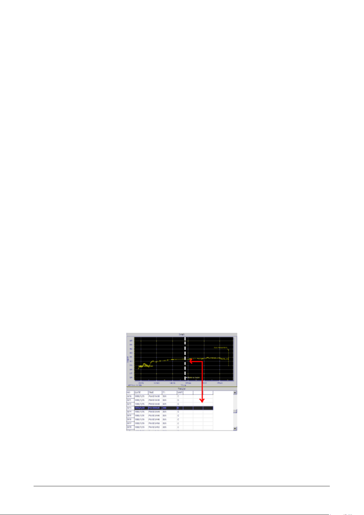
The vertical dash line in the graph will match the highlight row in the tabular. When clicking on another row in
the tabular, the vertical dash line will move to the correspondin
g position to match the time.
Page 9
Page 13

FREQ UENTLY ASKED QUE STION
1. I have connected thermometer to computer serial port and turned thermometer on, but it still shows
"NO CONNECTION."
It could be caused by that all serial port are occupied by other applications. Close all application,
restart your computer, and run SE318 again.
2. In TABULAR window, I saved a file. Can I use EXCEL to open this file?
If the decimal separator is comma (,) in your area, you cannot use CSV file because CSV
us
e comma to separate data. This will cause confusion (for example 23,6,C,24.6,C).
However, you can use TXT files instead. It uses tab to separate to data.
(For example: 23.6 C 24.6 C) and it can be accepted in EXCEL.
3. How to uninstall SE318?
Uninstall SE318 by launching the Add/Remove Programs applet out of the Control Panel,
highlighting the SE318, and clicking on the Add/Remove... button, then it will remove the SE318
folder and files from your comp
file
uter.
Page 10
Page 14

NOTES:
Page 11
Page 15

WARRANTY/DISCLAIMER
OMEGA ENGINEERING, INC. warrants this unit to be free of defects in materials and workmanship for a
period of 13 months from date of purchase. OMEGA’s WARRANTY adds an additional one (1) month
grace period to the normal one (1) year product warranty to cover handling and shipping time. This
ensures that OMEGA’s customers receive maximum coverage on each product.
If the unit malfunctions, it must be returned to the factory for evaluation. OMEGA’s Customer Service
Department will issue an Authorized Return (AR) number immediately upon phone or written request.
Upon examination by OMEGA, if the unit is found to be defective, it will be repaired or replaced at no
charge. OMEGA’s WARRANTY does not apply to defects resulting from any action of the purchaser,
including but not limited to mishandling, improper interfacing, operation outside of design limits,
improper repair, or unauthorized modification. This WARRANTY is VOID if the unit shows evidence of
having been tampered with or shows evidence of having been damaged as a result of excessive corrosion;
or current, heat, moisture or vibration; improper specification; misapplication; misuse or other operating
conditions outside of OMEGA’s control. Components in which wear is not warranted, include but are not
limited to contact points, fuses, and triacs.
OMEGA is pleased to offer suggestions on the use of its various products. However,
OMEGA neither assumes responsibility for any omissions or errors nor assumes liability for any
damages that result from the use of its products in accordance with information provided by
OMEGA, either verbal or written. OMEGA warrants only that the parts manufactured by it will be
as specified and free of defects. OMEGA MAKES NO OTHER WARRANTIES OR
REPRESENTATIONS OF ANY KIND WHATSOEVER, EXPRESS OR IMPLIED, EXCEPT THAT OF TITLE,
AND ALL IMPLIED WARRANTIES INCLUDING ANY WARRANTY OF MERCHANTABILITY AND
FITNESS FOR A PARTICULAR PURPOSE ARE HEREBY DISCLAIMED. LIMITATION OF
LIABILITY: The remedies of purchaser set forth herein are exclusive, and the total liability of
OMEGA with respect to this order, whether based on contract, warranty, negligence,
indemnification, strict liability or otherwise, shall not exceed the purchase price of the
component upon which liability is based. In no event shall OMEGA be liable for
consequential, incidental or special damages.
CONDITIONS: Equipment sold by OMEGA is not intended to be used, nor shall it be used: (1) as a “Basic
Component” under 10 CFR 21 (NRC), used in or with any nuclear installation or activity; or (2) in medical
applications or used on humans. Should any Product(s) be used in or with any nuclear installation or
activity, medical application, used on humans, or misused in any way, OMEGA assumes no responsibility
as set forth in our basic WARRANTY/ DISCLAIMER language, and, additionally, purchaser will indemnify
OMEGA and hold OMEGA harmless from any liability or damage whatsoever arising out of the use of the
Product(s) in such a manner.
RETURN REQUESTS/INQUIRIES
Direct all warranty and repair requests/inquiries to the OMEGA Customer Service Department. BEFORE
RETURNING ANY PRODUCT(S) TO OMEGA, PURCHASER MUST OBTAIN AN AUTHORIZED RETURN
(AR) NUMBER FROM OMEGA’S CUSTOMER SERVICE DEPARTMENT (IN ORDER TO AVOID
PROCESSING DELAYS). The assigned AR number should then be marked on the outside of the return
package and on any correspondence.
The purchaser is responsible for shipping charges, freight, insurance and proper packaging to prevent
breakage in transit.
FOR WARRANTY
RETURNS, please have the
following information available BEFORE
contacting OMEGA:
1. Purchase Order number under which the product
was PURCHASED,
2. Model and serial number of the product under
warranty, and
3. Repair instructions and/or specific problems
relative to the product.
FOR NON-WARRANTY REPAIRS,
consult OMEGA
for current repair charges. Have the following
information available BEFORE contacting OMEGA:
1. Purchase Order number to cover the COST
of the repair,
2. Model and serial number of the product, and
3. Repair instructions and/or specific problems
relative to the product.
OMEGA’s policy is to make running changes, not model changes, whenever an improvement is possible. This affords
our customers the latest in technology and engineering.
OMEGA is a registered trademark of OMEGA ENGINEERING, INC.
© Copyright 2010 OMEGA ENGINEERING, INC. All rights reserved. This document may not be copied, photocopied,
reproduced, translated, or reduced to any electronic medium or machine-readable form, in whole or in part, without the
prior written consent of OMEGA ENGINEERING, INC.
Page 16

M4933/1010
Where Do I Find Everything I Need for
Process Measurement and Control?
OMEGA…Of Course!
Shop online at omega.com
sm
TEMPERATURE
䡺⻬
Thermocouple, RTD & Thermistor Probes, Connectors, Panels & Assemblies
䡺⻬
Wire: Thermocouple, RTD & Thermistor
䡺⻬
Calibrators & Ice Point References
䡺⻬
Recorders, Controllers & Process Monitors
䡺⻬
Infrared Pyrometers
PRESSURE, STRAIN AND FORCE
䡺⻬
Transducers & Strain Gages
䡺⻬
Load Cells & Pressure Gages
䡺⻬
Displacement Transducers
䡺⻬
Instrumentation & Accessories
FLOW/LEVEL
䡺⻬
Rotameters, Gas Mass Flowmeters & Flow Computers
䡺⻬
Air Velocity Indicators
䡺⻬
Turbine/Paddlewheel Systems
䡺⻬
Totalizers & Batch Controllers
pH/CONDUCTIVITY
䡺⻬
pH Electrodes, Testers & Accessories
䡺⻬
Benchtop/Laboratory Meters
䡺⻬
Controllers, Calibrators, Simulators & Pumps
䡺⻬
Industrial pH & Conductivity Equipment
DATA ACQUISITION
䡺⻬
Data Acquisition & Engineering Software
䡺⻬
Communications-Based Acquisition Systems
䡺⻬
Plug-in Cards for Apple, IBM & Compatibles
䡺⻬
Data Logging Systems
䡺⻬
Recorders, Printers & Plotters
HEATERS
䡺⻬
Heating Cable
䡺⻬
Cartridge & Strip Heaters
䡺⻬
Immersion & Band Heaters
䡺⻬
Flexible Heaters
䡺⻬
Laboratory Heaters
ENVIRONMENTAL
MONITORING AND CONTROL
䡺⻬
Metering & Control Instrumentation
䡺⻬
Refractometers
䡺⻬
Pumps & Tubing
䡺⻬
Air, Soil & Water Monitors
䡺⻬
Industrial Water & Wastewater Treatment
䡺⻬
pH, Conductivity & Dissolved Oxygen Instruments
 Loading...