

Page 1
User’s Guide
Shop online at
omega.com
e-mail: [email protected]
For latest product manuals:
omegamanual.info
MADE IN CHINA
®
RH297
Pinless Moisture Psychrometer
with IR Thermometer + Bluetooth
Page 2

OMEGAnet®Online Service Internet e-mail
omega.com [email protected]
Servicing North America:
U.S.A.: Omega Engineering, Inc., One Omega Drive, P.O. Box 4047
ISO 9001 Certified
Canada: 976 Bergar, Laval (Quebec), H7L 5A1 Canada
Stamford, CT 06907-0047 USA
Toll-Free: 1-800-826-6342 Tel: (203) 359-1660
FAX: (203) 359-7700 e-mail: [email protected]
For immediate technical or application assistance:
U.S.A. and Canada: Sales Service: 1-800-826-6342/1-800-TC-OMEGA
Customer Service: 1-800-622-2378/1-800-622-BEST
Engineering Service: 1-800-872-9436/1-800-USA-WHEN
®
®
®
Servicing Asia:
China: 1698 Yi Shan Road, Unit 102, Min Hang District
Shanghai, China 201103 P.R.C.
Hotline: 800 819 0559/400 619 0559
e-mail: [email protected]
Servicing Europe:
Benelux: Toll-Free: 0800 099 3344 TEL: +31 20 347 21 21
Czech Republic: Frystatska 184, 733 01 Karviná, Czech Republic
France: Toll-Free: 0800 466 342 TEL: 01 57 32 48 17
Germany/ Austria: Daimlerstrasse 26, D-75392 Deckenpfronn, Germany
United Kingdom: OMEGA Engineering Ltd.
ISO 9001 Certified
FAX: +31 20 643 46 43 e-mail: [email protected]
TEL: +420-59-6311899 FAX: +420-59-6311114
e-mail: [email protected]
FAX: 01 57 32 48 18 e-mail: [email protected]
Toll-Free: 0800 8266342 TEL: +49 (0) 7056 9398-0
FAX: +49 (0) 7056 9398-29 e-mail: [email protected]
One Omega Drive, River Bend Technology Centre, Northbank
Irlam, Manchester M44 5BD United Kingdom
Toll-Free: 0800-488-488 TEL: +44 (0) 161 777-6611
FAX: +44 (0) 161 777-6622 e-mail: [email protected]
It is the policy of OMEGA Engineering, Inc. to comply with all worldwide safety and EMC/EMI regulations that
apply. OMEGA is constantly pursuing certification of its products to the European New Approach Directives.
OMEGA will add the CE mark to every appropriate device upon certification.
The information contained in this document is believed to be correct, but OMEGA accepts no liability for any errors it contains,
and reserves the right to alter specifications without notice.
WARNING: These products are not designed for use in, and should not be used for, human applications.
Page 3
User's Guide
Pinless Moisture Psychrometer
with IR Thermometer + Bluetooth
Model RH297
Page 4
Introduction
Congratulations on your purchase of the Extech MO297 with MeterLink bluetooth capabilities
for use with Flir infrared cameras. This Pinless Moisture Meter incorporates a Patented Builtin IR Thermometer and 20 Point Memory. Monitor moisture in wood and other building
materials with no surface damage with the Pinless Moisture sensor (Pin-type Moisture Probe
included). Measure Humidity and Air Temperature with built-in probe plus non-contact
InfraRed Temperature with patented IR design. Advanced functions provide Grains per
Pound, Dew Point and Vapor Pressure calculations. This meter is shipped fully tested and
calibrated and, with proper use, will provide years of reliable service.
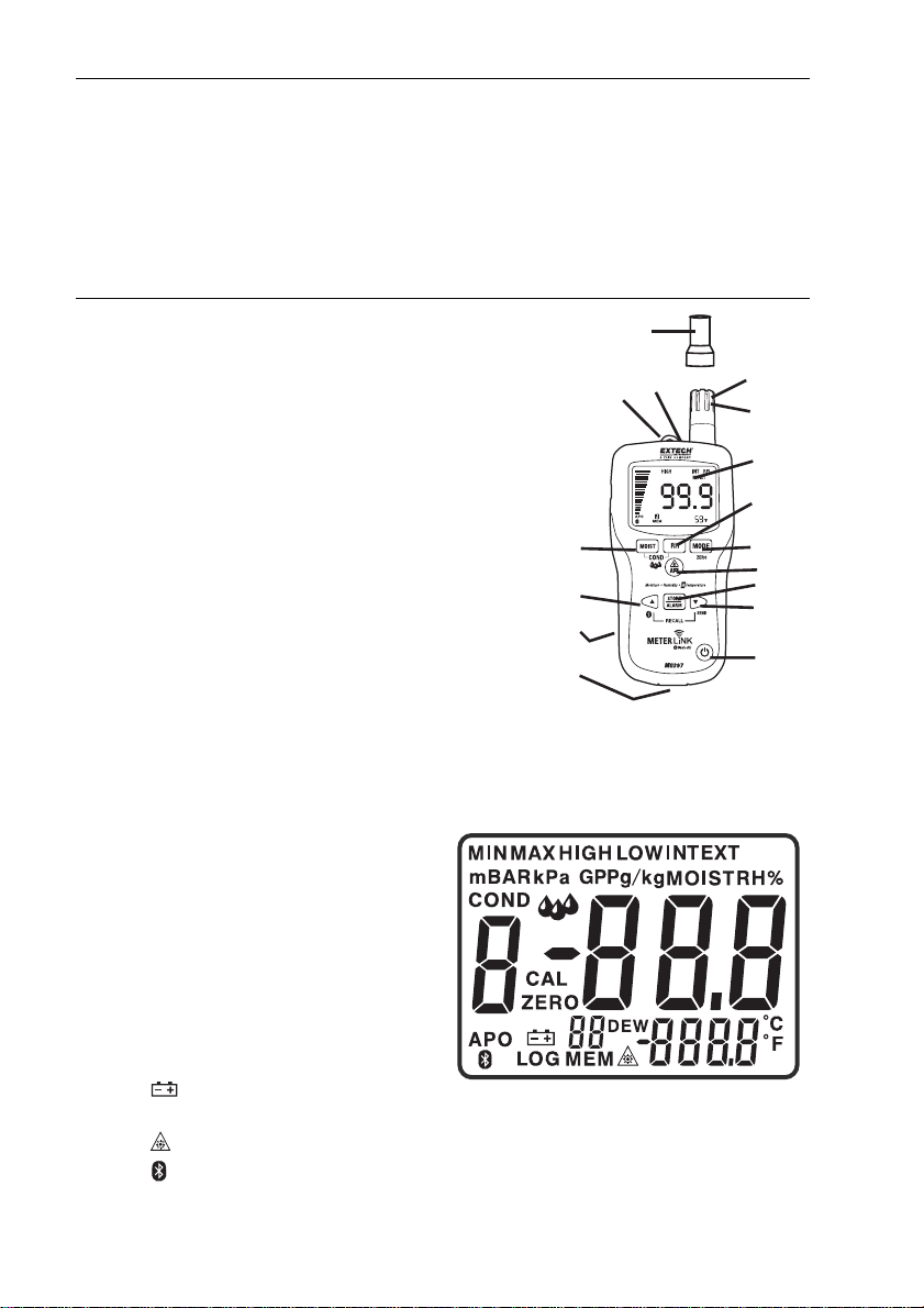
Meter Description
1. IR temperature sensor
2. Laser pointer
3. Humidity sensor
4. Temperature sensor
5. LCD display
6. Relative Humidity button
7. Mode/Zero Button
8. IR thermometer button
9. Alarm set button
10. Alarm adjust down / SEND button
11. ON/OFF power button
12. Remote pin probe input jack (bottom)
13. Battery compartment (rear)
14. Alarm adjust up / Bluetooth button
15. Moisture/Relative button
16. Protective cap
LCD Display
1. MIN MAX – Minimum and maximum value
2. HIGH LOW – Alarm limits
3. INT EXT – Internal/External probe
4. mBar – Vapor pressure
5. kPa – Vapor pressure
6. GPP – Grains per Pound
7. g/kg – Grains per kilogram
8. MOIST – Moisture mode
9. RH% - Relative Humidity mode
10. COND – Condensation mode
11. APO – Auto power off
12. DEW – Dew Point temperature
13. C/F – Temperature units
14.
- Low battery
15. MEM - Memory location indicator
- Laser pointer On
16.
17.
- Bluetooth On
15
14
13
12
16
2
1
3
4
5
6
7
8
9
10
11
REL
2
MO297 V3.2 07/10
Page 5

Safety
• Use extreme caution when the laser pointer beam is on
• Do not point the beam toward anyone's eye or allow the
beam to strike the eye from a reflective surface
• Do not use the laser near explosive gases or in other
potentially explosive areas
Features
• Quickly indicates the moisture content of materials with Pinless technology without
damaging the surface;
• Optional remote Pin-type probe (MO290-P) allows for moisture readings at different
penetration levels (3ft/0.9m cable length);
• Easy to read, large dual display with backlit feature;
• Simultaneously displays % moisture of wood or material being tested and Air
Temperature, IR Temperature, or Humidity
• Designed with patented IR design to measure non-contact surface temperature; 8:1
distance to spot ratio with 0.95 fixed emissivity
• Built-in Humidity/Temperature probe measures Relative Humidity,
• Air Temperature plus Grains Per Pound (GPP) and Dew Point (DP)
• Ambient and Surface Vapor Pressure
• Automatic calculation of differential Temperature (IR - DP)
• Min/Max and Data Hold
• 20 point internal memory
• Auto power off and low battery indication
Battery Replacement
1. Turn off the meter.
2. Remove one Philips head screw and lift off the rear battery cover.
3. Replace the 9V battery.
4. Secure the rear battery cover.
You, as the end user, are legally bound (EU Battery ordinance) to return all
used batteries, disposal in the household garbage is prohibited! You can
hand over your used batteries / accumulators at collection points in your
community or wherever batteries / accumulators are sold!
Disposal: Follow the valid legal stipulations in respect of the disposal of the
device at the end of its lifecycle
3
MO297 V3.2 07/10
Page 6

Operation
Powering the meter
1. Remove the RH sensor protective cap before use.
2. Press the power
3. If the
symbol appears or the meter does not turn on, replace the battery.
Humidity (Dew point, GPP, g/kg) Measurements
1. Press the power button to turn the meter on.
2. Press the RH button
3. Relative Humidity will be displayed in the primary display and the temperature will be
displayed in the secondary display.
4. Press the up or down arrow button to change the temperature units.
5. Press the MODE button to display the DEW point.
6. Press the MODE button to display GPP (°F) or g/kg (°C). Press the ▲or ▼button to
toggle between GPP or g/kg.
Pinless Moisture Measurements
1. Press the power button to turn the meter on.
2. Press the MOIST button to select Moisture measurement.” MOIST”, and “INT”
(internal pinless sensor) will appear in the display.
3. Hold the meter so that the rear sensor is away from any surface or your hand. The
reading should be near 0.0. If not, press and hold the ZERO button for more than 2
second and the ZERO icon appears.
4. Place the rear sensor on the surface of the material to be tested and read the relative
moisture content.
button to turn the meter on.
Pin Type Moisture Measurements
1. Connect the external pin probe to the jack on the bottom of the meter.
2. Press the power
3. Press the MOIST button twice to select Moisture measurement.” MOIST”, and “EXT”
(external pin probe) will appear in the display.
4. Press the probe pins into the material and read the % moisture content in the display.
button to turn the meter on.
4
MO297 V3.2 07/10
Page 7
Infrared Temperature Measurements
1. Press the power button to turn the meter on.
2. Press the IRT button to enable the IR thermometer and the laser pointer. The laser
pointer icon will flash while the mode is active.
3. Press the ▲or ▼button to change the temperature units
4. Aim the laser pointer at the surface to be measured and read the surface temperature
in the secondary display.
5. Release the IRT button. The last temperature measured and the laser icon will remain
on the display for approximately 10 seconds before returning to ambient temperature
measurement.
IRT MAX MIN display:
The meter can be set to display only the maximum or minimum temperature measured
during an IR scan.
1. With the meter in the IR hold mode, press the MODE button. “MIN” will appear in
the display.
2. Press the IRT button to enable the IR thermometer. The meter will display the
minimum temperature measured and will update only when a lower temperature is
measured.
3. Press the MODE button twice to enable the MAX mode and proceed as stated
above for the maximum temperature.
4. The MAX or MIN temperature is not stored when the function is exited. The unit
automatically exits MAX/MIN mode after approximately 10 seconds.
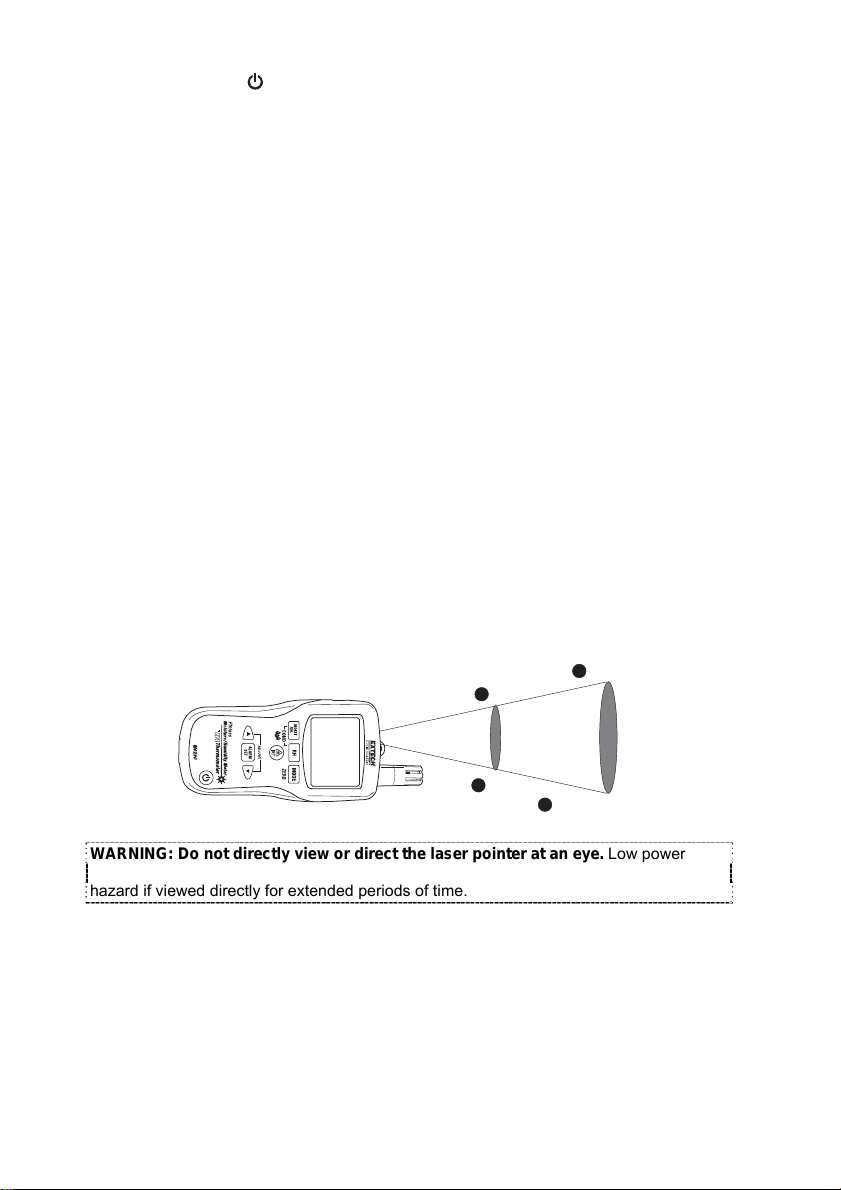
IR Field of View
Ensure that the desired target is larger than the spot size. As the distance from an object
increases, the spot size of the area measured by the meter becomes larger. The meter’s
field of view ratio is 8:1, meaning that if the meter is 8 inches (cm) from the target, the
diameter (spot) of the object under test must be at least 1 inch (cm). Refer below to the
field of view diagram.
WARNING: Do not directly view or direct the laser pointer at an eye. Low power
visible lasers do not normally present a hazard, but may present some potential for
hazard if viewed directly for extended periods of time.
1” @ 8”
20mm @ 160mm
40mm @ 320mm
2” @ 16”
5
MO297 V3.2 07/10
Page 8

Condensation Mode
The Condensation feature alerts the user when the surface temperature as measured by the
IR thermometer is close to or has reached the Dew Point temperature.
1. Press the power
2. Simultaneously press the MOIST and RH buttons. The “COND” icon will appear.
3. Point the meter at a surface, press the IRT button to measure the surface
temperature. The small display will indicate the IR surface temperature and the large
display will indicate the difference between the IR temperature and the Dew Point
temperature.
4. The meter will then report the potential for condensation on that surface in the
following manner
• If the temperature of the IRT is more than 14°C (25°F) above the Dew Point, the
temperature difference shall be displayed, with no other warning.
• If the temperature of the IRT is 3-14°C (5-25°F) above the Dew Point, the
temperature difference shall be displayed, along with a standard Condensation
Indicator icon. The meter shall beep once to confirm that the reading is in the risk
area.
• If the temperature of the IRT is less than 3°C (5°F) above the Dew Point, the
temperature difference shall be displayed, along with a flashing Condensation
Indicator icon. The meter shall beep twice to confirm that the reading is in the highrisk area.
5. Press the RH button to exit the mode.
button to turn the meter on.
Vapor Pressure Mode
Ambient Vapor Pressure
1. With the Condensation mode active, press the MODE button to display the Vapor
Pressure in mBAR (°F) or kPa (°C). Press the ▲or ▼button to toggle between mBAR
or kPa.
2. Press the MODE button to exit the Vapor Pressure mode.
Surface Vapor Pressure
1. Enter the Vapor Pressure mode as described above.
2. Press the IRT button and aim the laser pointer at the surface to be measured to
display the Surface Vapor Pressure in mBAR (°F) or kPa (°C).
Alarm High and Low Limit Setting
High and Low alarm points can be set for Humidity and Moisture measurements.
Humidity Alarm Set Procedure:
1. With RH% displayed, simultaneously press the RH and MODE buttons.
2. The “HIGH” icon will appear on the display.
3. Press the ▲or ▼button to set the high limit desired.
4. Press the STORE/ALARM SET button to save the value and proceed to the LOW set
value.
5. With the “LOW” icon in the display, Press the ▲or ▼button to set the low limit
desired.
6. Press the STORE/ALARM SET button to save the value and to return to the normal
mode.
7. If the humidity measurement is lower than the low alarm setting or higher than the
high alarm setting, the meter will beep once every second.
6
MO297 V3.2 07/10
Page 9

Moisture Alarm Set Procedure:
1. With MOIST displayed, simultaneously press the MOIST and MODE buttons.
2. The “HIGH” icon will appear on the display.
3. Press the ▲or ▼button to set the high limit desired.
4. Press the STORE/ALARM SET button to save the value and proceed to the LOW set
value.
5. With the “LOW” icon in the display, Press the ▲or ▼button to set the low limit
desired.
6. Press the STORE/ALARM SET button to save the value and to return to the normal
mode.
7. If the moisture measurement is lower than the LOW alarm setting, the meter will beep
once every second
8. If the moisture measurement is higher than the HIGH alarm setting, the meter will
beep continuously.
Data Memory Storage
Storing Readings:
1. With the data to be saved in the display, press the STORE button for 2 seconds until
the unit beeps. The data will be saved to the memory location indicated. The numeric
display above the MEM icon will then advance to the next location.
2. When the 20 memory locations are full, the unit will overwrite old saved readings
starting with memory location 01.
Recalling Stored Readings:
1. Simultaneously press and release the ▲and ▼ buttons to display stored readings.
The numeric display above the MEM icon will flash and the data stored in that location
will be displayed.
2. Press the ▲or ▼button to scroll through the memory locations.
3. To return to normal operating mode, press the STORE button.
Clearing Stored Data:
1. To clear stored data, press and hold the ▲and STORE buttons simultaneously until
CLR appears on the display.
Auto Power Off
The meter will enter a sleep mode after 30 minutes of inactivity. The meter will emit a
warning beep 15 seconds before shutting down.
To disable the APO feature, press the MODE button when turning the meter ON. The
“APO” icon will not appear, indicating it is disabled.
7
MO297 V3.2 07/10
Page 10
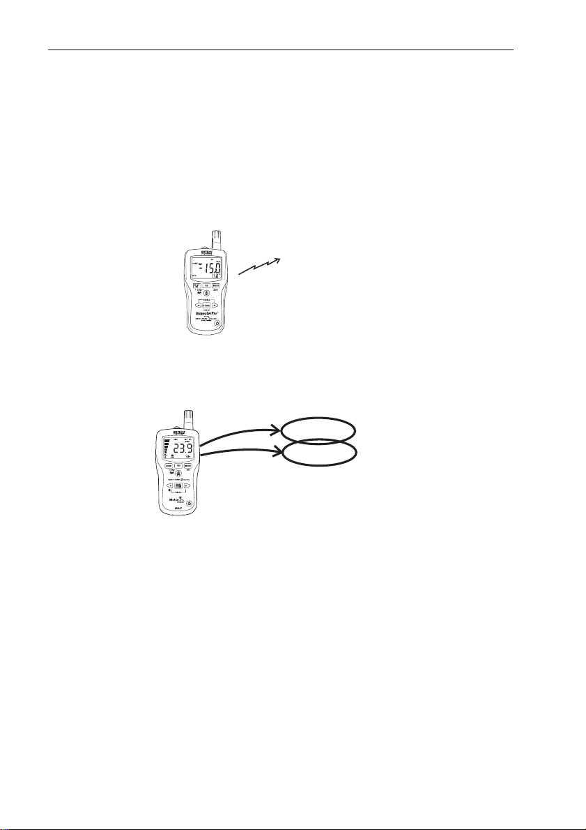
MeterLink™ Bluetooth Communication
This meter includes a Bluetooth module designed to communicate with the FLIR T/B200,
T/B300, T/B360, T/B400 or i/b60 cameras. The combination of a moisture meter and an IR
camera is used for analysis and documentation of moisture in buildings.
Setup
1. Enable the MO297 bluetooth by pressing and holding the ▲button for two seconds.
The bluetooth icon will appear in the display.
2. Pair the meter to the camera by following the “Pairing Bluetooth Devices” section in
the thermal camera manual.
3. Once paired, the data from the MO297 will be continuously displayed and updated on
the camera display.
4. Readings stored into memory can be recalled and applied to live thermal images.
Image Editing
A single or series of readings can be applied to a single image by saving and entering the
image edit mode. Data stored in the MO297 memory can also be added to the image.
MO297
8
MO297 V3.2 07/10
Page 11

T/B200, T/B300, T/B360, T/B400 Image Edit
1. Entering the camera Preview mode (single press of the image store button).
2. In Preview mode real time data or recalled memory data is no longer streamed to
the image but it is displayed in a preview box.
3. The data in the box can be applied to the image by pressing (3 seconds) the
MO297 ▼ / SEND button or the ADD button in the camera’s preview box.
4. Data applied to the image in this way will be enumerated.
i/B60 Image Edit
1. Press the trigger to store the image
2. Recall the image using the recall archive button (arrow in a box)
3. The real time data or recalled memory data is no longer streamed to the image but
it is displayed in a preview box.
4. The data in the box can be applied to the image by pressing (3 seconds) the
MO297 ▼ / SEND button or the camera’s trigger
5. Data applied to the image in this way will be enumerated.
Typical Moisture Measurement and Documentation Procedure
1. Using the camera, identify any potential damp areas behind walls and ceilings.
2. Use the Moisture meter to measure the moisture levels at various suspect locations
that may have been found.
3. When a spot of particular interest is located, store the moisture reading in the
moisture meter’s memory and identify the measurement spot with a handprint or other
thermal identifying marker.
4. Recall the reading from memory. The moisture meter will now continuously transmit
this reading via bluetooth.
5. Use the camera to take a thermal image of the area with the identifying marker. The
stored data from the moisture meter will also be saved on the image.
FCC Part 15
This equipment has been tested and found to comply with the limits for a Class B digital
device, pursuant to part 15 of the FCC Rules. These limits are designed to provide
reasonable protection against harmful interference in a residential installation. This
equipment generates, uses and can radiate radio frequency energy and, if not installed
and used in accordance with the instructions, may cause harmful interference to radio
communications. However, there is no guarantee that interference will not occur in a
particular installation. If this equipment does cause harmful interference to radio or
television reception, which can be determined by turning the equipment off and on, the
user is encouraged to try to correct the interference by one or more of the following
measures:
—Reorient or relocate the receiving antenna.
—Increase the separation between the equipment and receiver.
—Connect the equipment into an outlet on a circuit different from that to which the receiver
is connected.
—Consult the dealer or an experienced radio/TV technician for help.
Warning: Changes or modifications not expressly approved by the party responsible for
compliance could void the user's authority to operate the equipment.
9
MO297 V3.2 07/10
Page 12

Specifications
Function ycaruccA egnaR
Pinless Moisture ylno evitaleR 9.99 ot 0
Ext. Pin Moisture ylno evitaleR 9.99 ot 0
Pinless Depth Up to 0.75” (19mm)
RH Measurement HR%3 ± %01 ot 0
11 to 90% ± 2.5%RH
91 to 100% 3%RH
Air Temperature -29 to 77°C (-20 to 170°F)
IR Temp
Display 3-digit primary display, 4-digit secondary display
Vapor Pressure 0 to 20.0kPA, calculated from temperature and RH
Dew Point -30 to 100°C (-22 to 199°F)
Mixing Ratio 0-999GPP (0 to 160g/kg)
Sample Rate 2 per second
Backlight White LED
Memory 20 point memory
Bluetooth range 32 feet (10 meters) approximately
Operating Temperature 4 to 43°C (40 to 110°F)
Storage Temperature -30 to 60°C (-14 to 140°F)
Operating Humidity 90%, 0-30°C (32-86°F), 75%, 30-40°C (86-104°F),
Storage Humidity 90%
Power Supply 9V battery
Battery Life 6-8 weeks (4 hrs/day use), using alkaline batteries
Auto Power Off (APO) After 30 minutes (nominal) inactivity. The APO function can be
APO Quiescent Current 50µA maximum
Dimensions 165x70x38mm (6.5x2.8x1.5’)
-4 to 31° F ± 9°F
32°F
33 to 392° F Greater of ±3.5% or ±9°F
-20 to-1°C ± 4.5° C
0°C ± 1°C
1 to 200°C
measurements
45%, 104-122°F (40-50°C)
disabled by the user.
)zo4.7( g012 thgieW
± 2.0°C (3.6°F)
F°2 ±
Greater of ±3.5% or ± 4.5°C
10
MO297 V3.2 07/10
Page 13

WARRANTY/DISCLAIMER
OMEGA ENGINEERING, INC. warrants this unit to be free of defects in materials and workmanship
for a period of 13 months from date of purchase. OMEGA’s WARRANTY adds an additional one (1)
month grace period to the normal one (1) year product warranty to cover handling and shipping
time. This ensures that OMEGA’s customers receive maximum coverage on each product.
If the unit malfunctions, it must be returned to the factory for evaluation. OMEGA’s Customer Service
Department will issue an Authorized Return (AR) number immediately upon phone or written
request. Upon examination by OMEGA, if the unit is found to be defective, it will be repaired or
replaced at no charge. OMEGA’s WARRANTY does not apply to defects resulting from any action of
the purchaser, including but not limited to mishandling, improper interfacing, operation outside of
design limits, improper repair, or unauthorized modification. This WARRANTY is VOID if the unit
shows evidence of having been tampered with or shows evidence of having been damaged as a
result of e xcessive corrosion; or current, heat, moisture or vibration; improper specification;
misapplication; misuse or other operating conditions outside of OMEGA’s control. Components in
which wear is not warranted, include but are not limited to contact points, fuses, and triacs.
OMEGA is pleased to offer suggestions on the use of its various products. However,
OMEGA neither assumes responsibility for any omissions or errors nor assumes liability
for any damages that result from the use of its products in accordance with information
provided by OMEGA, either verbal or written. OMEGA warrants only that the parts
manufactured by the company will be as specified and free of defects. OMEGA MAKES
NO OTHER WARRANT I E S OR REPRESE N T A T I O N S OF AN Y KIND WHATSOE V E R ,
EXPRESSED OR IMPLIED, EXCEPT THAT OF TITLE, AND ALL IMPLIED WARRANTIES
INCLUDING ANY WARRANTY OF MERCHANTABILITY AND FITNESS FOR A PARTICULAR
PURPOS E A RE HEREBY DISCL AI MED. LIMITA TION OF LIABILI TY: The remedie s of
purchaser set forth herein are exclusive, and the total liability of OMEGA with respect to
this order, whether based on contract, warranty, negligence, indemnification, strict
liability or otherwise, shall not exceed the purchase price of the component upon which
liability is based. In no event shall OMEGA be liable for consequential, incidental or
special damages.
CONDITIONS: Equipment sold by OMEGA is not intended to be used, nor shall it be used: (1) as a
“Basic Component” under 10 CFR 21 (NRC), used in or with any nuclear installation or activity; or (2)
in medical applications or used on humans. Should any Product(s) be used in or with any nuclear
installation or activity, medical application, used on humans, or misused in any way, OMEGA
assumes no responsibility as set forth in our basic WARRANTY / DISCLAIMER language , and,
additionally, purchaser will indemnify OMEGA and hold OMEGA harmless from any liability or
damage whatsoever arising out of the use of the Product(s) in such a manner.
Direct all warranty and repair requests/inquiries to the OMEGA Customer Service Department.
RETURN REQUESTS/INQUIRIES
BEFORE RETURNING ANY PRODUCT(S) TO OMEGA, PURCHASER MUST OBTAIN AN AUTHORIZED
RETURN (AR) NUMBER FROM OMEGA’S CUSTOMER SERVICE DEPARTMENT (IN ORDER TO AVOID
PROCESSING DELAYS). The assigned AR number should then be marked on the outside of the return
package and on any correspondence.
The purchaser is responsible for shipping charges, freight, insurance and proper packaging to
prevent breakage in transit.
FOR WARRANTY
following information available BEFORE
contacting OMEGA:
1. Purchase Order number under which
the product was PURCHASED,
2. Model and serial number of the product
under warranty, and
3. Repair instructions and/or specific
problems relative to the product.
OM E GA’ s poli c y is to mak e runn i ng ch a ng es, not mo d el c h ang e s , wh e nev e r an im pro v e me n t is po s si ble .
This affords our customers the latest in technology and engineering.
OMEGA is a registered trademark of OMEGA ENGINEERING, INC.
© Copyright 2012 OMEGA ENGINEERING, INC. All rights reserved. This document may not be copied, photocopied, repro-
duced, translated, or reduced to any electronic medium or machine-readable form, in whole or in part, without the prior written consent of OMEGA ENGINEERING, INC.
RETURNS, please have the
FOR NON-WARRANTY REPAIRS,
consult
OMEGA for current repair charges. Have the
following information available BEFORE
contacting OMEGA:
1. Purchase Order number to cover the
COST of the repair,
2. Model and serial number of theproduct, and
3. Repair instructions and/or specific problems
relative to the product.
Page 14

Where Do I Find Everything I Need for
Process Measurement and Control?
OMEGA…Of Course!
Shop online at omega.com
TEMPERATURE
䡺⻬
Thermocouple, RTD & Thermistor Probes, Connectors, Panels & Assemblies
䡺⻬
Wire: Thermocouple, RTD & Thermistor
䡺⻬
Calibrators & Ice Point References
䡺⻬
Recorders, Controllers & Process Monitors
䡺⻬
Infrared Pyrometers
PRESSURE, STRAIN AND FORCE
䡺⻬
Transducers & Strain Gages
䡺⻬
Load Cells & Pressure Gages
䡺⻬
Displacement Transducers
䡺⻬
Instrumentation & Accessories
FLOW/LEVEL
䡺⻬
Rotameters, Gas Mass Flowmeters & Flow Computers
䡺⻬
Air Velocity Indicators
䡺⻬
Turbine/Paddlewheel Systems
䡺⻬
Totalizers & Batch Controllers
pH/CONDUCTIVITY
䡺⻬
pH Electrodes, Testers & Accessories
䡺⻬
Benchtop/Laboratory Meters
䡺⻬
Controllers, Calibrators, Simulators & Pumps
䡺⻬
Industrial pH & Conductivity Equipment
DATA ACQUISITION
䡺⻬
Data Acquisition & Engineering Software
䡺⻬
Communications-Based Acquisition Systems
䡺⻬
Plug-in Cards for Apple, IBM & Compatibles
䡺⻬
Data Logging Systems
䡺⻬
Recorders, Printers & Plotters
HEATERS
䡺⻬
Heating Cable
䡺⻬
Cartridge & Strip Heaters
䡺⻬
Immersion & Band Heaters
䡺⻬
Flexible Heaters
䡺⻬
Laboratory Heaters
ENVIRONMENTAL MONITORING AND CONTROL
䡺⻬
Metering & Control Instrumentation
䡺⻬
Refractometers
䡺⻬
Pumps & Tubing
䡺⻬
Air, Soil & Water Monitors
䡺⻬
Industrial Water & Wastewater Treatment
䡺⻬
pH, Conductivity & Dissolved Oxygen Instruments
SM
M5207/0812
 Loading...