

Page 1
User’s Guide
Shop online at
omega.com
e-mail: [email protected]
For latest product manuals:
www.omegamanual.info
RDA520
RDA740
RDA760
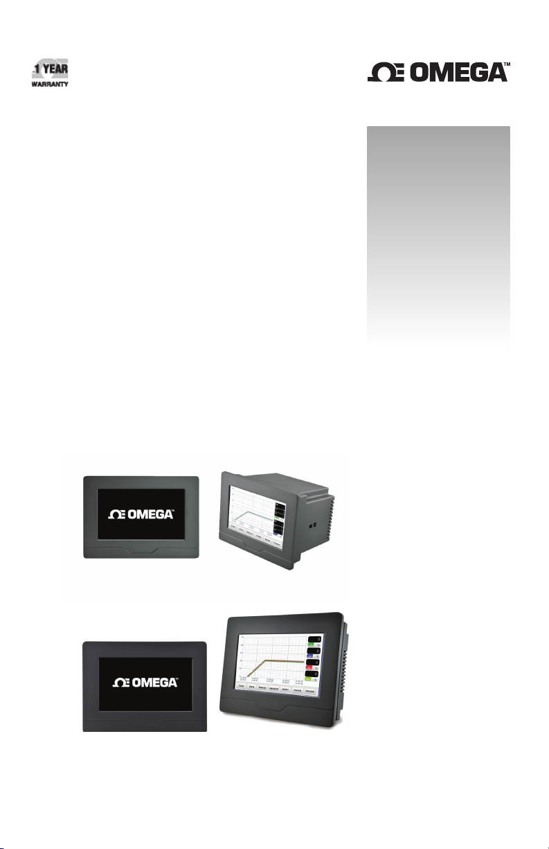
Paperless Recorder
Page 2

omega.com [email protected]
Servicing North America:
U.S.A. Omega Engineering, Inc.
Headquarters: Toll-Free: 1-800-826-6342 (USA & Canada only)
Customer Service: 1-800-622-2378 (USA & Canada only)
Engineering Service: 1-800-872-9436 (USA & Canada only)
Tel: (203) 359-1660 Fax: (203) 359-7700
e-mail: [email protected]
For Other Locations Visit omega.com/worldwide
The information contained in this document is believed to be correct, but OMEGA accepts no liability for any errors it
contains, and reserves the right to alter specifications without notice.
Page 3

WARRANTY/DISCLAIMER
OMEGA ENGINEERING, INC. warrants this unit to be free of defects in materials and
workmanship for a period of 13 months from date of purchase. OMEGA’s WARRANTY adds an
additional one (1) month grace period to the normal one (1) year product warranty to cover
handling and shipping time. This ensures that OMEGA’s customers receive maximum coverage
on each product.
If the unit malfunctions, it must be returned to the factory for evaluation. OMEGA’s Customer
Service Department will issue an Authorized Return (AR) number immediately upon phone
or written request. Upon examination by OMEGA, if the unit is found to be defective, it
will be repaired or replaced at no charge. OMEGA’s WARRANTY does not apply to defects
resulting from any action of the purchaser, including but not limited to mishandling, improper
interfacing, operation outside of design limits, improper repair, or unauthorized modification.
This WARRANTY is VOID if the unit shows evidence of having been tampered with or shows
evidence of having been damaged as a result of excessive corrosion; or current, heat, moisture
or vibration; improper specification; misapplication; misuse or other operating conditions
outside of OMEGA’s control. Components in which wear is not warranted, include but are not
limited to contact points, fuses, and triacs.
OMEGA is pleased to offer suggestions on the use of its various products. However,
OMEGA neither assumes responsibility for any omissions or errors nor assumes
liability for any damages that result from the use of its products in accordance with
information provided by OMEGA, either verbal or written. OMEGA warrants only
that the parts manufactured by the company will be as specified and free of defects.
OMEGA MAKES NO OTHER WARRANTIES OR REPRESENTATIONS OF ANY KIND
WHATSOEVER, EXPRESSED OR IMPLIED, EXCEPT THAT OF TITLE, AND ALL IMPLIED
WARRANTIES INCLUDING ANY WARRANTY OF MERCHANTABILITY AND FITNESS
FOR A PARTICULAR PURPOSE ARE HEREBY DISCLAIMED. LIMITATION OF LIABILITY:
The remedies of purchaser set forth herein are exclusive, and the total liability of
OMEGA with respect to this order, whether based on contract, warranty, negligence,
indemnification, strict liability or otherwise, shall not exceed the purchase price of
the component upon which liability is based. In no event shall OMEGA be liable for
consequential, incidental or special damages.
CONDITIONS: Equipment sold by OMEGA is not intended to be used, nor shall it be used: (1) as
a “Basic Component” under 10 CFR 21 (NRC), used in or with any nuclear installation or activity;
or (2) in medical applications or used on humans. Should any Product(s) be used in or with any
nuclear installation or activity, medical application, used on humans, or misused in any way,
OMEGA assumes no responsibility as set forth in our basic WARRANTY / DISCLAIMER language,
and, additionally, purchaser will indemnify OMEGA and hold OMEGA harmless from any
liability or damage whatsoever arising out of the use of the Product(s) in such a manner.
RETURN REQUESTS/INQUIRIES
Direct all warranty and repair requests/inquiries to the OMEGA Customer Service Department.
BEFORE RETURNING ANY PRODUCT(S) TO OMEGA, PURCHASER MUST OBTAIN AN
AUTHORIZED RETURN (AR) NUMBER FROM OMEGA’S CUSTOMER SERVICE DEPARTMENT (IN
ORDER TO AVOID PROCESSING DELAYS). The assigned AR number should then be marked on
the outside of the return package and on any correspondence.
The purchaser is responsible for shipping charges, freight, insurance and proper packaging to
prevent breakage in transit.
FOR WARRANTY RETURNS, please have the
following information available BEFORE
contacting OMEGA:
1. Purchase Order number under which
the product was PURCHASED,
2. Model and serial number of the product
under warranty, and
3. Repair instructions and/or specific
problems relative to the product.
OMEGA’s policy is to make running changes, not model changes, whenever an improvement is possible.
This affords our customers the latest in technology and engineering.
OMEGA is a trademark of OMEGA ENGINEERING, INC.
© Copyright 2017 OMEGA ENGINEERING, INC. All rights reserved. This document may not be copied, photocopied,
reproduced, translated, or reduced to any electronic medium or machine-readable form, in whole or in part, without
the prior written consent of OMEGA ENGINEERING, INC.
FOR NON-WARRANTY REPAIRS,
consult
OMEGA for current repair charges. Have the
following information available BEFORE
contacting OMEGA:
1. Purchase Order number to cover the
COST of the repair,
2. Model and serial number of the product, and
3. Repair instructions and/or specific problems
relative to the product.
Page 4

Where Do I Find Everything I Need for
Process Measurement and Control?
OMEGA…Of Course!
Shop online at omega.com
TEMPERATURE
MU
Thermocouple, RTD & Thermistor Probes, Connectors, Panels & Assemblies
MU
Wire: Thermocouple, RTD & Thermistor
MU
Calibrators & Ice Point References
MU
Recorders, Controllers & Process Monitors
MU
Infrared Pyrometers
PRESSURE, STRAIN AND FORCE
MU
Transducers & Strain Gages
MU
Load Cells & Pressure Gages
MU
Displacement Transducers
MU
Instrumentation & Accessories
FLOW/LEVEL
MU
Rotameters, Gas Mass Flowmeters & Flow Computers
MU
Air Velocity Indicators
MU
Turbine/Paddlewheel Systems
MU
Totalizers & Batch Controllers
pH/CONDUCTIVITY
MU
pH Electrodes, Testers & Accessories
MU
Benchtop/Laboratory Meters
MU
Controllers, Calibrators, Simulators & Pumps
MU
Industrial pH & Conductivity Equipment
DATA ACQUISITION
MU Communications-Based Acquisition Systems
MU Data Logging Systems
MU Wireless Sensors, Transmitters, & Receivers
MU Signal Conditioners
MU Data Acquisition Software
HEATERS
MU
Heating Cable
MU
Cartridge & Strip Heaters
MU
Immersion & Band Heaters
MU
Flexible Heaters
MU
Laboratory Heaters
ENVIRONMENTAL
MONITORING AND CONTROL
MU
Metering & Control Instrumentation
MU
Refractometers
MU
Pumps & Tubing
MU
Air, Soil & Water Monitors
MU
Industrial Water & Wastewater Treatment
MU
pH, Conductivity & Dissolved Oxygen Instruments
M0000/0619
Page 5

RDA520-TC
MODEL COVERED
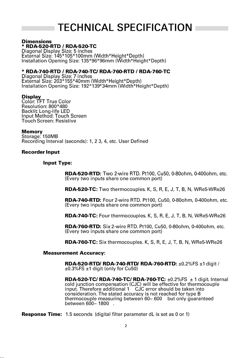
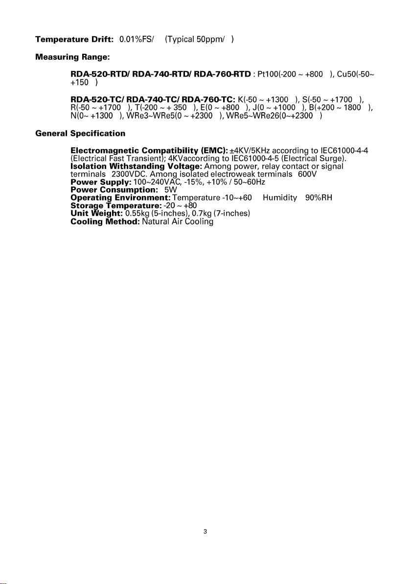
Description: 5 inch TFT Display, 2 T/C Inputs Paperless Recorder
Supply Power: 100~240VAC,50/60Hz
RDA520-RTD
RDA740-TC
RDA740-RTD
RDA760-TC
RDA760-RTD
Description: 5 inch TFT Display, 2 RTD Inputs Paperless Recorder
Supply Power: 100~240VAC,50/60Hz
Description: 7 inch TFT Display, 4 T/C Inputs Paperless Recorder
Supply Power: 100~240VAC,50/60Hz
Description: 7 inch TFT Display, 4 RTD Inputs Paperless Recorder
Supply Power: 100~240VAC,50/60Hz
Description: 7 inch TFT Display, 6 T/C Inputs Paperless Recorder
Supply Power: 100~240VAC,50/60Hz
Description: 7 inch TFT Display, 6 RTD Inputs Paperless Recorder
Supply Power: 100~240VAC,50/60Hz
INTRODUCTION
The RDA Paperless Recorder integrates measurement, display, alarm, data logging into one slim
instrument. It provides multi-channel recording with a touch screen display as well as alarm
generating capability. Depending on the model, the RDA Paperless Recorder provides 2, 4, or
6 inputs. There are two different size panels, 5-inch, 7-inch. The RDA-740 and RDA-760 models
are only 40mm thick which allows it to be installed in machinery or equipment where space is
limited. The main parameters are set in one single interface through the industrial grade touch
screen.
1. All-in-one
Input, display, monitoring, recording and
output are all integrated in one paperless
recorder. There is no external HMI required
and the Recorder is simple and easy to install.
2. Touch Screen Interface
All the configuration and operation is done
on the industrial graded touch screen without
any hardware PIN setting.
3. Durable Components
Low power consumption. 12 months warranty
on quality. HMI graphics and datalogging are
processed by one ARM processor in dual CPU
mode. EMC testings complied (±4KV/5KHz
according to IEC61000-4-4 (Electrical Fast
Transient); 4KVaccording to IEC61000-4-5
(Electrical Surge).
4. Outstanding anti-interence
Ultra performance hardware greatly reduce
the temperature drift and the interference
among the input channels. The measurement
accuracy of multi-channel reaches that of
single channel.
5. Abundant Recording Function
Real-time trend graph, bar graph and history
trend graph are provided. Measured data
and alarm record can be shown on screen as
a report table. Storage size is 150MB. Data
stored can be viewed as graph or table and
exported to external USB storage deivce.
The RDA Paperless Recorder does not have a sealed housing. The device
should not be exposed to excessive dust, moisture, or shock during
installation. Only professionally trained personnel should operate and
maintain this device.
Page 6
℃
℃
≤
℃
Page 7
≤ ℃ ℃
℃
℃ ℃ ℃ ℃ ℃
℃ ℃ ℃
≥ ≥
≤
℃ ≤
℃
℃
℃ ℃
Page 8
Page 9
Page 10
Page 11
Page 12
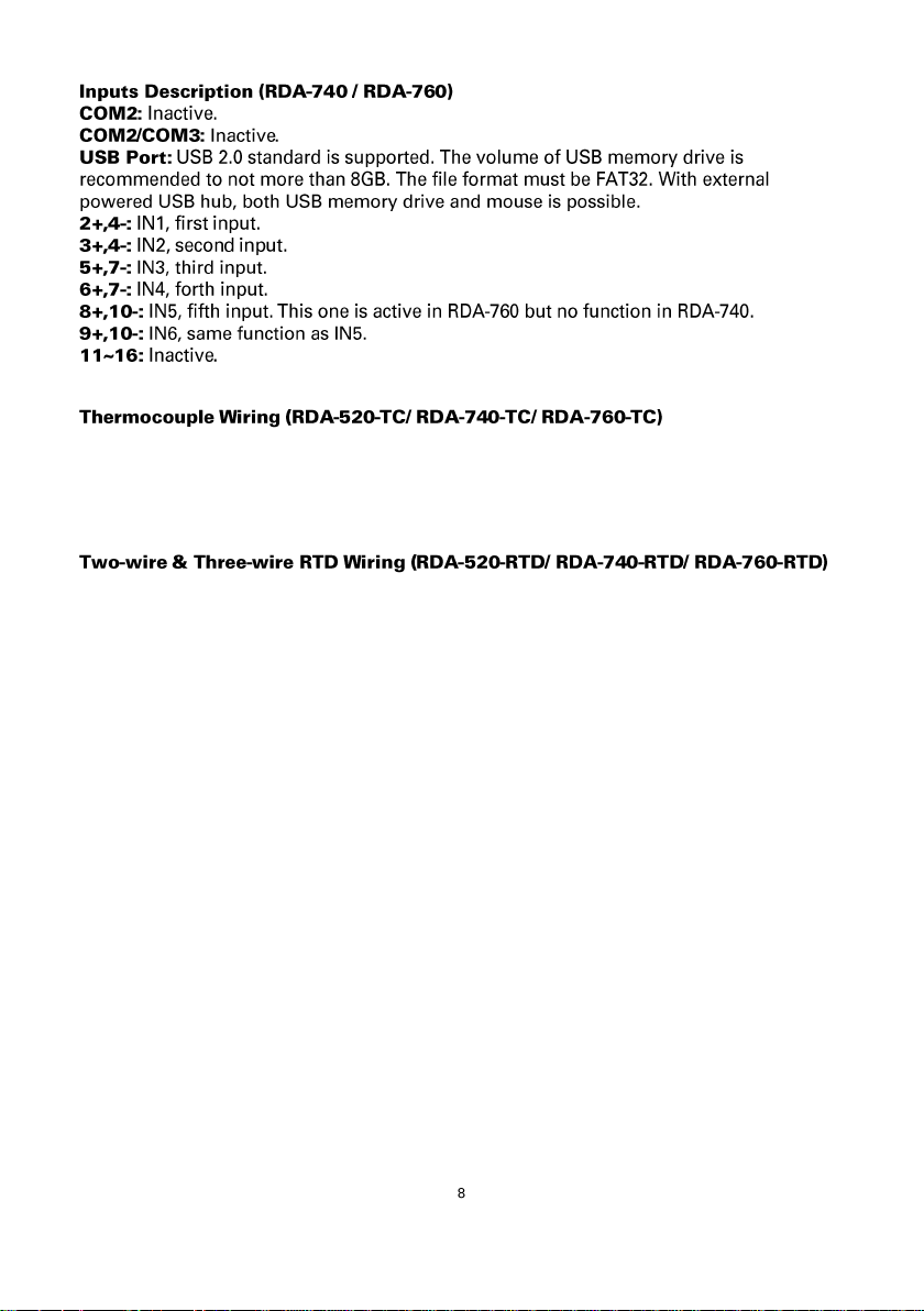
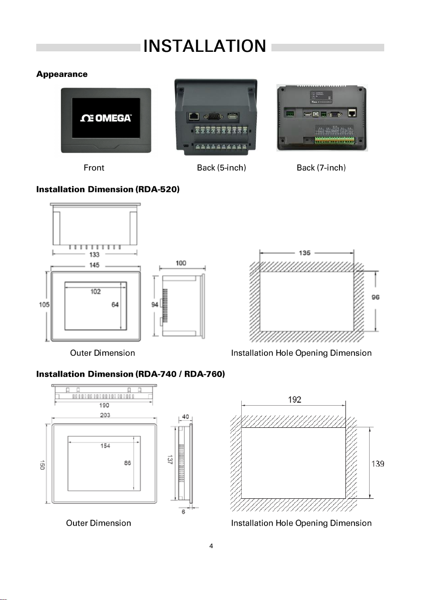
RDA-TC: Qualified compensation wires of thermocouple should be directly connected to the back
of the instrument. Do not connect the incorrect polarity of compensation wires. Cold junction
compensation error will occur if the above requirements are not met. Cu50 copper resistor can be
connected terminal JC and negative of thermocouple (RDA-520: terminal 17 and 20; RDA740/RDA-760: terminal 1 and 4) as thermocouple cold junction compensation temperature. Shortconnection will have ice-point compensation.
RTD connection can be applied either two-wire or three-wire method by setting the “B” digit in
“AF” parameter. Two-wire method saves quantity of wire connections and allows more number
of input channels. However resistance of lead wire is required to be measured to eliminate error.
Three-wire method is the traditional wiring method. If the resistance of each lead wire is equal,
the resistance value is not required to be measured. However the number of channels possible is
half of that of two-wire method. The instrument applies a number of policies to leverage the error
brought by the lead wire resistance. In applications requiring higher accuracy, three-wire method
is recommended. The resistance of each lead wire should be less than 2Ω.
Lead wire resistance in two-wire method can be saved to parameter “Sc” to compensate during
measurement. However, the lead wire resistance (copper or aluminum material) changes with
temperature. The instrument can compensate the change of lead wire resistance according to
room temperature sensor. However this kind of compensation is not suitable in the application
that the change of lead wire resistance does not synchronize the change of instrument
temperature. Three-wire method is recommended in this situation.
Page 13
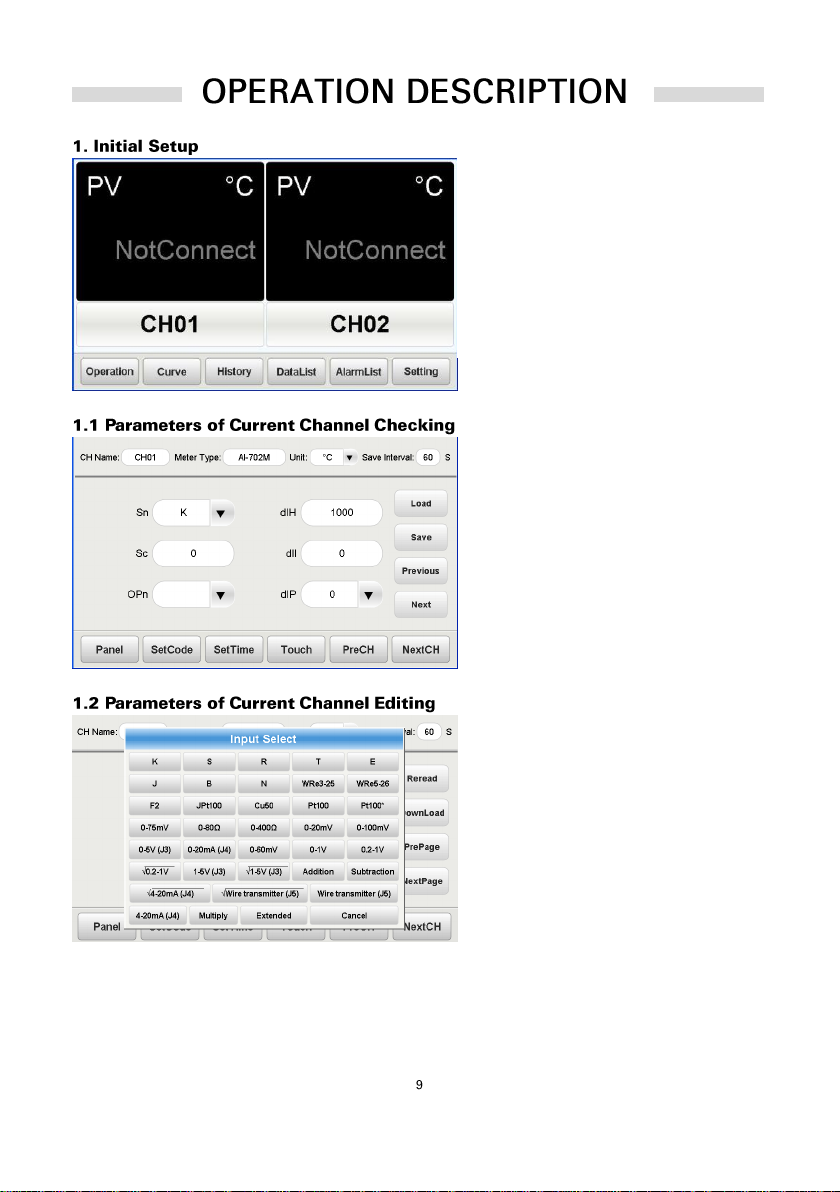
Once the instrument is power on,
the main screen will be displayed.
Press “Setting” to go to instrument
configuration. The default
password is “111”.
The instrument automatically loads
parameters once this page is loaded.
Press “Previous” to go back to the
previous page. Press “Next” to go to
the next page.
Press the white space of “Sn” input
and the dialogue screen will pop up
to change the values. Choose the
input specification from the
dialogue. Press “Cancel” button in
the bottom right to close the box.
Page 14
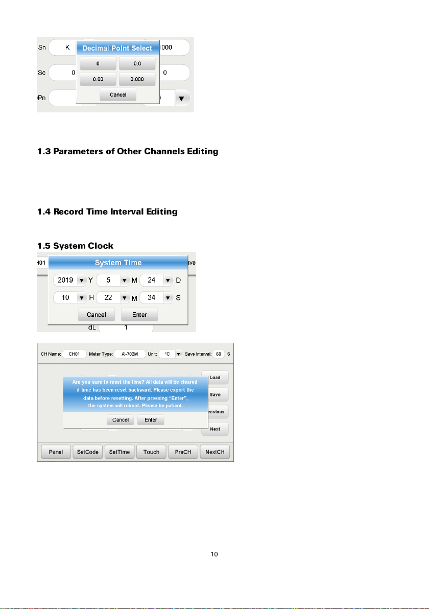
Press “DiP” decimal place to select the
corresponding decimal place. Only
parameters “Sn” and “dIP” are automatically
saved instantly. Other parameters will turn to
red if the values are changed. Press “Save” at
the rightmost column will save all the
unsaved parameters. Those parameters in red
will return to black again.
Press “SetTime” to edit the system time.
Please set the correct time to match with local
time. Press “Enter” will reset the time. Any
saved data later than the time reset will be
erased.
RDA is a multi-channel recorder. After setting one channel, please press “NextCH” to go to the
parameter setting page of next channel or “PreCH” to go to that of previous channel. Please
repeat the above steps until all channels are configured.
Press “Save Interval” to edit the time interval of data recording. The unit is in second.
Page 15
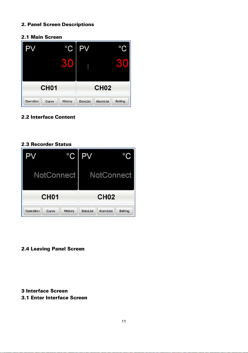
When the power is on, or press
“Panel” button in interfaces of
“History”, “Alarm”, “Report” and
“Setting”, it will go to back to main
panel screen.
When an alarm is activated, the
background color of channel title
will turn red from light grey. Enter
“AlarmList” will see the details of
alarm. PV shows “NotConnect”
when the specific channel is not
connected to the internal hardware.
PV shows a value when it is
connected. When input is out of
range, PV blinks a warning message
“OrAL” (abbreviation of over-
range-alarm).
PV is the measured value. The unit is shown on top. The title of channel is shown below the PV
values.
Pressing corresponding button “Curve” (Real time curve), “History” (History Trend Graph),
“DataList” (Data Report), “AlarmList” (Alarm Report), and “Setting” (System Setting) will to go
particular function screen. Press the channel title will go the corresponding operation interface of
that channel. For example, pressing “CH01” will go to interface screen of channel number 1.
In the main panel screen, press the channel title will go the corresponding operation interface of
that channel.
Page 16
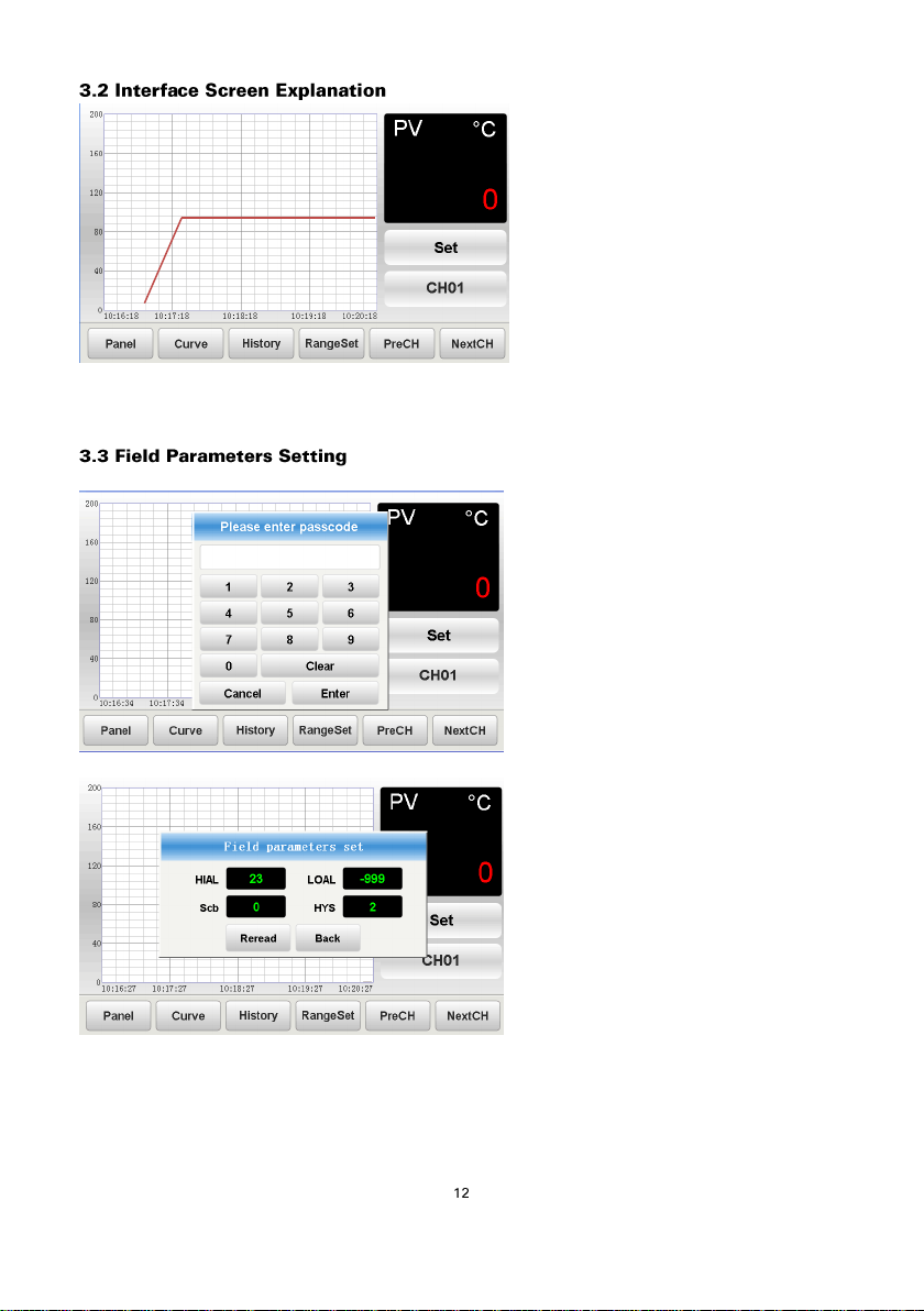
The PV measure values, unit and
channel title are shown on right
column. The corresponding
curve of PV values is shown on
left.
Press “Set” button the open the
“Field Parameter Set” dialog
screen. It is password protected.
It will automatically show the
current HIAL (High limit alarm),
LoAL (Low limit alarm), Scb
(Input shift correction) and HYS
(alarm hysteresis). Press
“Reread” to refresh these
parameters.
Page 17
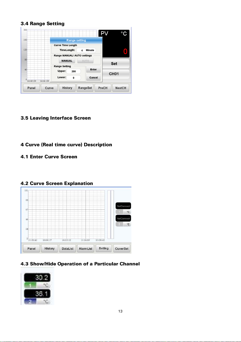
Press “RangeSet” in the bottom the
set the time range of curve and high
limit and low limit of the curve.
Press “Manual” in the dialog box
activate the manul setting mode.
The range setting will abide to the
values entered. Press “Auto” to
activate the automatic fitting mode.
The system will automatically fit the
curve and the range setting will
have no effect.
The PV values, unit and channel
number of each channels are shown
on right column. The channel
number presenting is fixed in
ascending order. When a channel is
“NotConnect”(Not connected), no
graph is shown.
Press the number tag on the right column to show or hide the particular
channel.
Press the green tag (channel 1) will turn grey out the curve of channel 1.
Pressing it again will make it reappear.
Pressing the corresponding button “Panel” (Main Screen), “Curve” (Real time curve), “History”
(History Trend Graph) will to go particular function screen.
Press “Curve” button in the screen of “Panel”, “History”, “AlarmList” and “Setting” will go the
real time curve screen.
Page 18
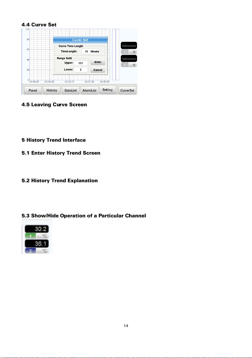
Curve Time length can be entered.
The value supports decimal place.
Unit is in minute.
Press the number tag on the right column to show or hide the particular channel.
Press the green tag (channel 1) will turn grey out the curve of channel 1. Pressing it
again will make it reappear.
Pressing the corresponding button “Panel” (Main Screen), “History” (History Trend Graph),
“DataList” (Data Report), “AlarmList” (Alarm Report), and “Setting” (System Setting) will to go
particular function screen.
Press “History” button in the screen of “Panel”, “Curve”, “AlarmList” and “Setting” will go the
history trend graph screen.
The PV values, unit and channel number of each channels are shown on right column. The
channel number presenting is fixed in ascending order. When a channel is “notConnected”, no
graph is shown.
Page 19
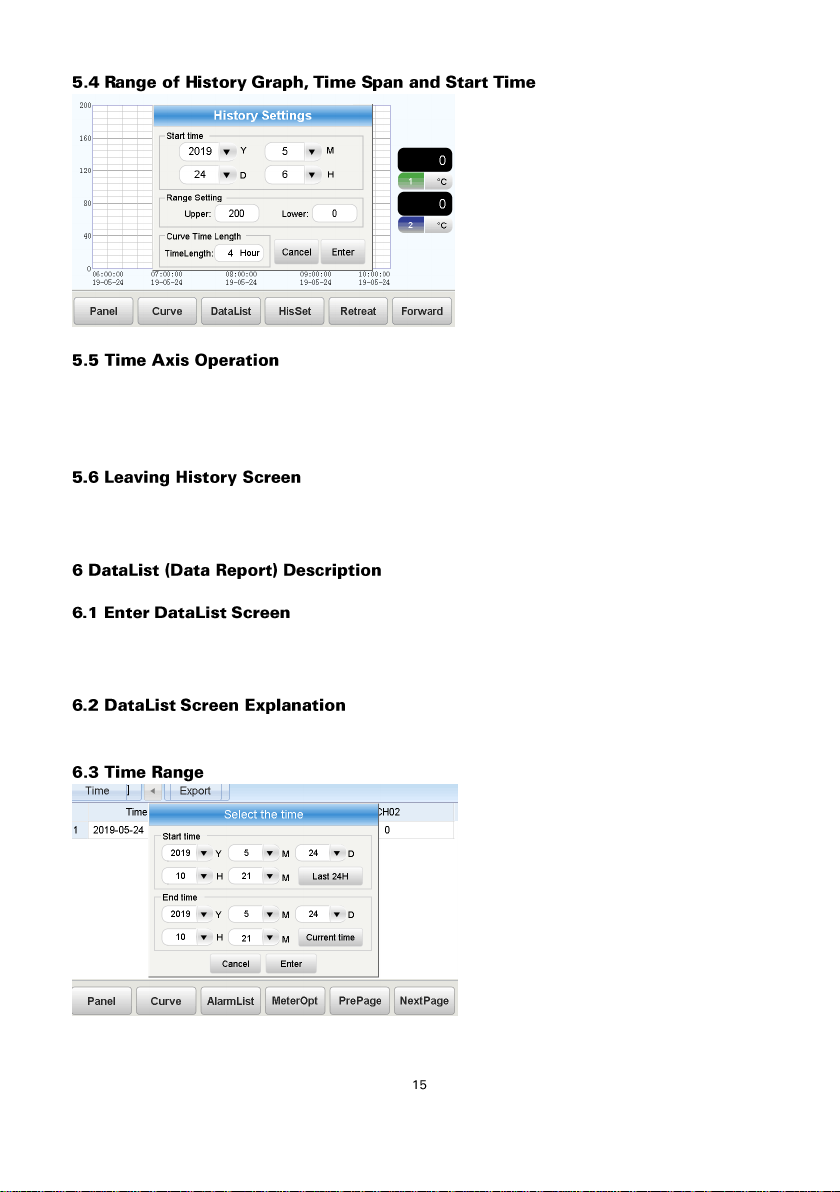
Press “Retreat” in the bottom to shift the time axis back for 3/4 time of the curve time. Press
Press “HisSet” button at the bottom
to pop up the dialog box.
Curve Time length can be entered.
The value supports decimal place.
Unit is in minute.
Press “Time” to pop out the time
span setting dialog. Please “Last
24H” to retrieve the last 24 hours
data without pressing “Enter”.
Please “Current Time” to retrieve
the data from start time to current
system time without pressing
“Enter”.
“Forward” in the bottom to shift the time axis forward for 3/4 time of the curve time. No time axis
shift happens when the action of shift exceeds the current time.
Pressing the corresponding button “Panel” (Main Screen), “Curve” (Real Time Curve), “DataList”
(Data Report) will to go to particular function screen.
Press “DataList” button in the screen of “Panel”, “Curve” “History”, “AlarmList” and “Setting”
will go the real time curve screen.
The PV measured values and time of each channel displayed.
Page 20
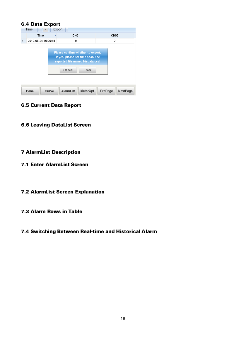
Plug in a USB memory drive. Press
“Export” on the top row. The
recorded data within the time range
enquired will be exported to the
drive in a file named “Hisdata.csv”.
Press “NextPage” to scroll down and “PrePage” to scroll up the data report table.
Pressing the corresponding button “Panel” (Main Screen), “Curve” (Real Time Curve),
“AlarmList” (Alarm Report) and “Setting” will to go to particular function screen.
Press “AlarmList” button in the screen of “Panel”, “Curve” “History”, “DataList” and “Setting”
will go the real time curve screen.
The alarm details are displayed, if any. Filtering feature is provided.
Press “NextPage” to scroll down and “PrePage” to scroll up the alarm report table.
Every time going into AlarmList screen, by default the system shows real-time alarms. Press “Real”
(Real-time) to switch “His.” (Historical alarm). Press “His.” to switch back to “Real”.
Page 21
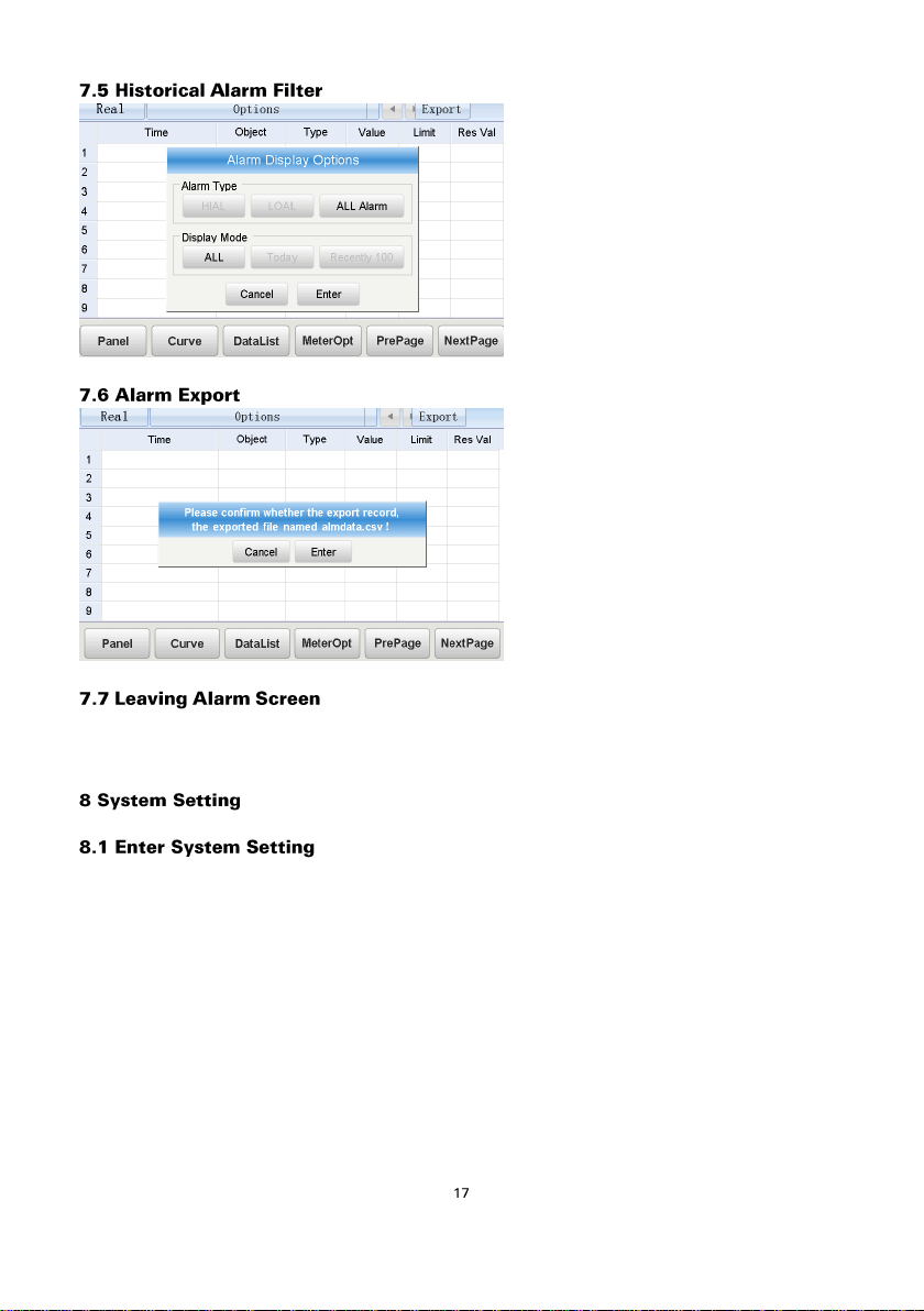
Press “OPTION” in the top row will
pop out the filter option of alarms.
Plug in a USB memory drive. Press
“Export” on the top row. The alarm
list enquired will be exported to the
drive in a file named “almdata.csv”.
Pressing the corresponding button “Panel” (Main Screen), “Curve” (Real Time Curve), “DataList”
(Data Report) and “Setting” will to go to particular function screen.
Press “Setting” button in the screen of “Panel”, “Curve” “History”, “DataList” and “AlarmList”
will go the system setting screen. This section is password protected. The initial password is “111”.
Page 22
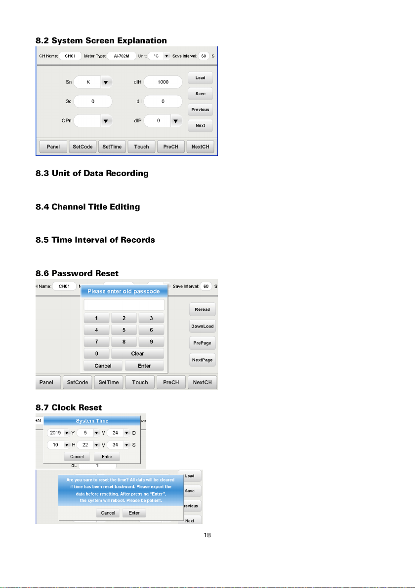
The screen shows the current “CH
Name” (title of channel), “Meter
Type” (Internally Fixed), “Unit”, “Save
Interval” (Time interval of recording)
and instrument parameters. All the
values will be refreshed once this
screen is entered. Switching channels
will refresh too. Please make sure
saving the parameters before
switching channels.
Press “SetCode” to pop up password
resetting dialog box. Input the old
password when it prompts. If it fails,
the dialog box will disappear. If the
password is correct, the dialog box
will prompt to input a new 3-digit
password. Press enter to confirm.
Press “SetTime” to edit the system
clock. Please set the correct time to
match with local time. Press “Enter”
will reset the time. Any saved data
later than the time reset will be erased.
Press the white editing space beside “Unit” to pop up the unit selection box.
Press the white editing space beside “CH Name” to pop up the text input dialog box.
Press the white editing space beside “Save Interval” to pop up the text input dialog box.
Page 23
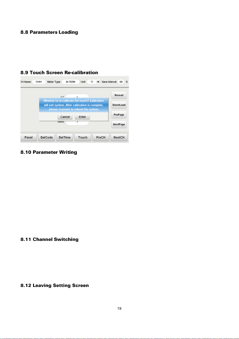
Press “Touch” to re-calibrate the touch
screen. It is calibrated in the factory.
Advanced operation and
manufacturer support may be
required for this operation.
Entering this screen or switching channels will refresh the parameters. Any unsaved change in
parameters will lost. “NotConnect” refers to the lost communication connection between the
interface software and hardware. No action of “Load” or “Save” can be done. Please check for any
communication interference at the back RS232/RS485 terminals.
Press the white edit space beside the parameter label can edit the values. Those with pull-down
symbol on the right will pop up a selection box. Those without the symbol will pop up a text
input box. Press “Cancel” to quit the input operation.
Only parameters “Sn” (Input specification) and “dIP” (decimal place) are automatically saved
instantly. Other parameters will turn to red if the values are changed. Press “Save” at the
rightmost column will save all the unsaved parameters. Those parameters in red will return to
black again.
Editing these two parameters, “Sn” and “diP” will ask the instrument to refresh all parameters.
Please set these two parameters in the very beginning.
Press “PreCH” at the bottom to switch to the parameter page of previous channel. If the current
channel is already the first channel, no action will be taken.
Press “NextCH” at the bottom to switch to the parameter page of next channel. If the current
channel is already the last channel, no action will be taken.
Pressing the corresponding button “Panel” (Main Screen) will to go to main screen.
Page 24
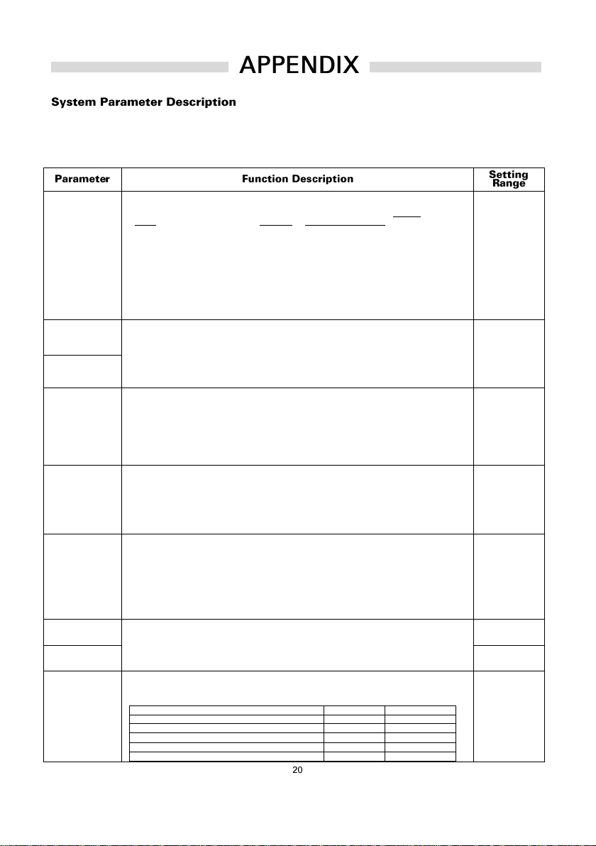
Input
specification (Sn
x)
Available input speciation:
K, S, R, T, E, J, B, N, WRe3-WRe25, WRe5-WRe26, F2 (High Temperature Radiation
Thermometer), BA2 (JPt100), Cu50, Pt100, Pt100* (-100.00 ~ +300.00°C), 0~75mV, 0~80Ω,
0~400Ω, 0~20mV, 0~100mV, 0~5V1, 0~20mA2, 0~60mV, 0~1V, 0.2~1V, √0.2~1𝑉, 1~5V1,
√
1~5𝑉1, Addition4, Subtraction5, √4~20𝑚𝐴2, √2 − 𝑤𝑖𝑟𝑒 𝑡𝑟𝑎𝑛𝑠𝑚𝑖𝑡𝑡𝑒𝑟3, 2-wire transmitter3,
4~20mA2, Multiply6, Extended
1
Available only when optional J3 module card purchased.
2
Available only when optional J4 module card purchased.
3
Available only when optional J5 module card purchased.
Input specification should be compatible with input module, such as TC module for thermocouple and
mV inputs while RTD module for two-wire RTD.
4
Addition: Set Sn3, Sn4 or Sn5 = “Addition” (internal value 41), it becomes the sum of the inputs of
previous channels. E.g. if Sn5=41, PV5=PV1+PV2+PV3+PV4.
5
Subtraction: Set Sn3=42, then PV3=PV1-PV2
6
Multiply: Set Sn3=40, PV3=PV1*PV2
Digital Input
High Limit
(dIH x)
dIH/dIL define the corresponding scale of linear inputs such as mV, 0~5V, 1~5V,
0~10mA, 4~20mA, interpreting the measured physical unit. The range of signal shown is
-1999 ~ +9999 with decimal place defined by parameter dIP. When the temperature input
is retransmitted, dIH/dIL also define the high/low limit of temperature.
For example, a pressure transmitter transmits the pressure to a standard 1~5V signal to
input channel 1. The input at 1V indicates the pressure=0MPa and 5V indicates the
pressure=1MPa. The expected display resolution is 0.001MPa. The parameters
recommended are Sn1=33, dIP1=3, dIL1=0.000, dIH1=1.000
-9990~+30000
linear units or
0.1℃
Digital Input
Low Limit
(dIL x)
Input Shift
Correction
(Sc x)
Sc provides shift correction to the internal error of sensor or input signal or the error of
cold junction compensation in the instrument. When 2-wire RTD is used, Sc corrects the
error due to lead wires of RTD.
For thermocouple or three-wire RTD inputs, the units of Sc is 0.1℃. For example, when
Sc=-100, the measured temperature will be 10℃ lower.
For two-wire RTD inputs, the magnitude of correction = (Sc* signal unit). The signal unit
of Pt100 or 0~400ohm input is 0.02Ω while that of Cu50 or 0~240 Ω input is 0.012 Ω. For
example, when Sc=-50, input type is Pt100, the correction will be -50 * 0.02 Ω=-1 Ω. If the
lead wire resistance is 1 Ω, this cancels out the lead wire resistance.
-1999~+4000
units or 0.1℃
Retransmission
Number
(OPn)
Available option (internal data value, description)
Alarm output (0, OUTP port as alarm)
Transmit CH1 (1, OUTP port as retransmission from channel 1)
Transmit CH2 (2, OUTP port as retransmission from channel 2)
Transmit CH3 (3, OUTP port as retransmission from channel 3)
Transmit CH4 (4, OUTP port as retransmission from channel 4)
Min (Re-transmit the minimum value among all channels (defined by Cn) to OUTP)
Max (Re-transmit the maximum value among all channels (defined by Cn) to OUTP)
0~8
Decimal Point
of Input
(dIP x)
dIPx is set to select decimal place and display resolution of channel x.
(1) Linear inputs: Display resolution corresponding to 0,1,2,3 are 0, 0.0, 0.00
and 0.000
(2) Thermocouple or RTD inputs: dIP sets the display resolution of
temperature. dIP=0, display resolution is 1℃. dIP=1, display resolution is
0.1℃.
Note: dIP is only effective in display. The internal temperature resolution is fixed as
0.1°C or 1 linear unit. There is no effect on the communication and retransmission. When
the temperature resolution is set as 0.1°C, the resolution becomes 1℃ when it is over
1000℃.
0~3
High Limit of
Retransmission
Current (OPH)
When OUTP is used as re-transmission, OPL/OPH define the low/high limit of retransmisson. The unit is 0.1mA.
For example, to transmit the channel 1 input 0~600℃ into 4~20mA output, the
parameters should be set as below:
dIL1=0, dIH1=600, OPn=1, OPL=40, OPH=200
0~220
Low limit of
Retransmission
Current (OPL)
0~110
Alarm Position
(ALP x)
The two digit of ALP respectively indicates the alarm output allocation of LoAL and
HIAL. 0 refers no alarm output. 1,2,3,4,5,6,7 respectively sends alarm output to OP1,
OP2, AL1, AL2, AU1, AU2 and MIO. OP2, AL2 and AU2 only works on dual channel
relay modules.
LoAL
HIAL
No alarm
0 0 OP1 1 1
OP2 (Dual channel relay module installed)
2 2 AL1 3 3
AL2 (Dual channel relay module installed)
4
4
0~77
The letter x in the parameter title refers to channel number. RDA-520 provides two channels
recording feature thus H.ALx means HiAL1 and HiAL2. RDA-740 provides four channels
recording feature thus H.ALx means HiAL1~4. RDA-760 provides six channels recording feature
thus H.ALx means HiAL1~6.
Page 25
AU1 5 5
AU2 (Dual channel relay module installed)
6 6 MIO 7 7
Example setting as below:
ALP1=43, low limit alarm (L.AL) of channel 1 output to AL2,
ALP2=53, low limit alarm (L.AL) of channel 2 output to AU1, and both high limit
alarms(H.AL) of both channel are sent to AL1.
High Limit
Alarm (HIALx)
When PVx > HIALx, high limit alarm is activated. When PVx < (HIALx-dFx), the alarm is
deactivated. Set HIALx to its maximum value will disable this alarm.
-1999~+9999
linear unit or
1°C
Low Limit
Alarm (LoALx)
When PVx < LoALx, low limit alarm is activated. When PVx > (LoALx+dFx), the alarm is
deactivated. Set LoALx to its minimum value will disable this alarm.
-1999~+9999
linear unit or
1°C
Dead Band
(dFx)
dF is set to avoid high frequent alarm on/off actions caused by process input fluctuation.
Dead band is also known as insensitive sector or lag.
0~999.9℃ or
0~9999 linear
unit
Advanced
Function
(AF)
The formula of AF value is:
AF=B*2 + D*8 + E*16 + H*128
B=0, RTD input use two-wire wiring;
B=1, RTD input use three-wire wiring (suitable module required);
D=0, Normal;
D=1, Low limit alarms of all channels are changed to high limit alarms.
E=0, Normal;
E=1, Set M2(MIO) and M3(OUPT) supporting single channel input only.
H=0, Normal;
H=1, For thermocouple or RTD input, the measured value PV=PV*dIH / 2000.0. Addition
in input specification can be further applied.
Example setting
To make use of all alarms to high limit alarms,
D=1, then AF = 1*8 = 8.
Digital Filter
(dL x)
The value of dF will determine the ability of noise filtering.
0: no filtering;
1: filtering with mean;
2~40: filtering with mean and integral.
When a large value is set, the measurement input is stabilized but the response speed is
slow. Under environment with great interference, increasing dF gradually will adjust the
momentary fluctuation of measured value falling between 2 to 5 unit.
When the instrument is being metrological verified, dF can be set to 0 or 1 to increase the
response speed.
0~40
NO/NC Switch
(nonc)
Single channel relay module provides both normal open and normal close output. Dual
relay output module only provides NO output. This parameter can define the NO action
to NC.
nonc=0, L3 dual dual relay installed in MIO, OP1, OP2 AL1, AL2, AU1 and AU2 is
normal open, NO.
nonc=127, all module used as alarm turns to normal close, NC.
Formula of nonc is as below:
nonc = A*1 + B*2 + C*4 + D*8 + E*16 + F*32 + G*64
A,B,C,D,E,F,G respectively set NO/NC output of OP1, OP2, AL1, AL2, AU1, AU2 and
MIO. 0 means the corresponding output is NO, and 1 means NC output.
0 ~63, 127
 Loading...