

Page 1

Shop online at
omega.com
e-mail: [email protected]
For latest product manuals:
www.omegamanual.info
SM
Page 2

omega.com [email protected]
U.S.A.: Omega Engineering, Inc., One Omega Drive, P.O. Box 4047
Stamford, CT 06907-0047 USA
Toll-Free: 1-800-826-6342 (USA & Canada only)
Customer Service: 1-800-622-2378 (USA & Canada only)
Engineering Service: 1-800-872-9436 (USA & Canada only)
Tel: (203) 359-1660 Fax: (203) 359-7700
e-mail: [email protected]
The information contained in this document is believed to be correct, but OMEGA accepts no liability for any errors it contains, and reserves
the right to alter specifications without notice.
Page 3
CONTENTS
PREFACE 1
1 General 2
1
1.1 RS-232C communications interface 2
1.2 RS-485 communications interface 2
1.3 Ethernet 2
1.4 MODBUS protocol 2
2
2 Communications specifications 3
2.1 Serial communications 3
2.2 Ethernet communications 3
3 Confirmation of communications specifications and
3
settings
6
3.1 Switch settings 6
3.2 Settings from this unit
4 Connections 8
4
4.1 Connection precautions
4.2 Communications cables
4.3 Connection of High order communication RS-232C
4.4 Connection of High order communication RS-485
4.5 Connection of Low order communication RS-485
5 MODBUS protocol 14
5
5.1 Transmission mode of message 15
5.2 Data time interval 16
5.3 Message configuration 16
5.4 Message creation 22
5.5 Function code 23
5.6 Process in abnormality 28
5.7 Reference table 30
5.8 Range number table 96
6
8
10
11
12
Page 4
Introduction
This manual describes the specifications and operation of three communications interfaces (RS-232C, RS-485
and Ethernet) of the RD9900 series graphic recorders.
The individual part for each communication is explained separately in [In case of RS-232C], [In case of RS-485]
and [in case of Ethernet], and the common part is explained all together. Please read the required part carefully. Be
sure to confirm the model code of the communications interface of this unit you purchased.
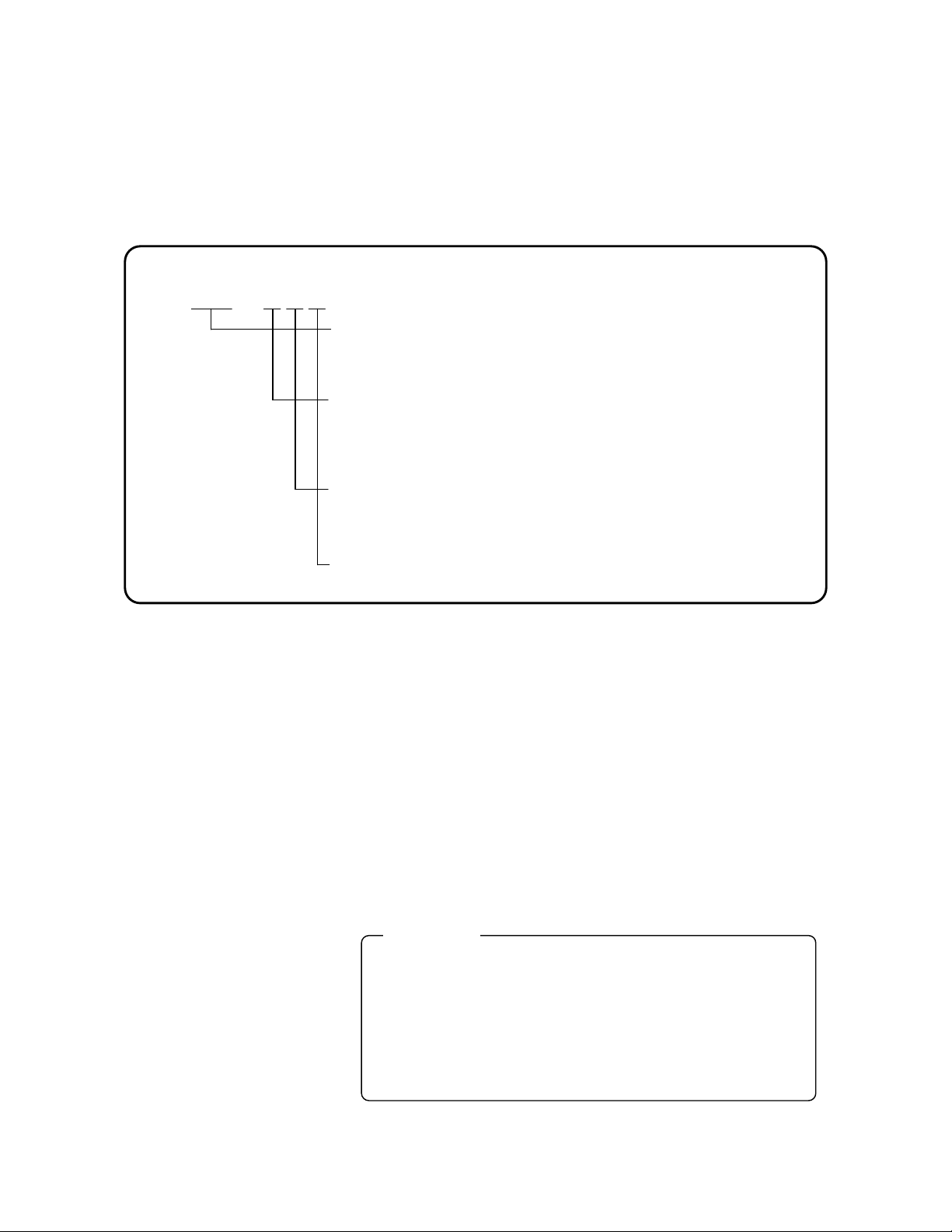
RD99
Measurement points/Sampling rate
06: 6-point input /100ms
12: 12 point input /100ms
Communication interface (Option)
Blank: None
C24: High order: RS232C (High order)/RS485 (High order)
Switchable, Low order: RS485
Alarm output, contact input, Power output for transmitter (Option)
Blank: None
AL12: Alarm relay output (12 points)
Power supply,
Blank: Standard power supply
1. Other manuals to be consulted
This manual is for the communications interface only. For the installations of this instrument, please refer to the
following separate manuals:
1) RD9900 General Instruction Manual
2) RD9900 Mounting/connections edition Instruction Manua
* For the personal computer (PC) you use, refer to the manual attached to the PC.
2. Caution display
This manual contains explanation with . Observe these precautions when operating and
handling the communications interface, otherwise damage of this unit, deterioration in performance or
operation failure may occur.
Precaution
Precaution
Precaution
(1) The right is reserved to change the contents of this manual at any time without
notice.
(2) The contents of this manual have been prepared professionally. However, if
you have any questions, or notice of error or an omission of descriptions
found on this manual, please contact your nearest OMEGA sales agent.
(3) OMEGA is not responsible for any results influenced by the operation of this
communications interface, irrespective of item (2) above.
- 1 -
Page 5

1 . General
1
The communications interfaces available in this unit are Ethernet as standard and 2 kinds of serial
communications, RS-232C/RS485, as an option. Via these communications, a PC can receive
measured data and set various parameters.
1.1 RS-232C communications interface
The RS-232C is the data communications standard being set and issued by EIA (Electronic Industries
Association) in the USA and the correspondence Japanese standard is JIS C 6361.
This standard covers the interfaces between the MODEM and the connected data terminal units, and specifies
electrical and mechanical specifications only. Most of the RS-232C communications interfaces are being used in
PCs and industrial instruments such as the RD9900 series graphic recorder, and do not completely conform to this
standard. Signal wire numbers and connectors of the RS-232C communications interface may differ from those
specified in the standard. Also, since this standard does not specify any software parts, so-called [data
transmission procedures], units having the RS-232C communications interface cannot be interconnected with
each other unconditionally. For these reasons, users must survey and check the specifications and transmission
procedures in advance of units being connected. However, if a unit connected is a PC or similar device that can
optionally program the specifications, most units can be connected via proper software programs created by a
systems engineer.
1.2 RS-485 communications interface
The RS-485 communications interface can communicate with multiple RD9900 series graphic recorders (up to 31
sets) in parallel by signals conforming to the RS-485.
There are few PCs having the RS-485 communications interface. However, since these communications
interfaces are characterized with serial communications, it is easily connectable to a PC having the RS-232C
communications interface by using an RS-232C RS-485 signal-converting unit. A line converter (Model
SC8-10) is available for RS-232C RS-485 signal conversion from OMEGA.
1.3 Ethernet
Ethernet is the communications standard specified in IEEE802.3 and is the most widely installed small-sized LAN
technology. The RD9900 series graphic recorder is connected to a LAN established by the Ethernet and performs
reception of measured data, setting of various parameters, etc.
For the specifications of this unit, connections for the Ethernet, etc., refer to the general manual for this
unit.
1.4 MODBUS protocol
The RD9900 series graphic recorder employs MODBUS protocol as the communications protocol.
The MODBUS protocol has RTU mode and ASCII mode that can be selected by keys on the front of this unit or
the communications.
By using the MODBUS protocol, operation of measurement, setting, etc. to instruments can be performed.
Ethernet interface performs by implementing the MODBUS protocol on TCP protocol packet.
* MODBUS is a registered trademark of Schneider Automation Inc.
- 2 -
Page 6
2 . Communications specifications
2
5
2.1 Serial communications
Specifications of the serial communications of this unit are as follows. * mark shows factory default settings.
Start-stop synchronization system
Half-duplex (polling selecting system)
Protocol: MODBUS protocol
Transmission mode: RTU mode* or ASCII mode
Transmission speed: 19200 bps or 9600 bps* selectable
Start bit: 1 bit
Data length: 7 bits or 8 bits* (depended on transmission mode)
Parity bit: Even, Odd or Non* (none) (depended on transmission mode)
Stop bit: 1 bit* or 2 bits (depended on transmission mode)
Transmission code: Binary* or ASCII (depended on transmission mode)
Error check: CRC-16* or LRC (depended on transmission mode)
External units precedence communications system
Data transmission procedure: No procedure
Signals used: Transmission/reception of data only (Control signal not used)
2.2 Ethernet communications
Specifications of the Ethernet communications of this unit are as follows.
Media: Ethernet (10BASE-T/100BASE-TX)
Communications mode: Full-duplex/Half-duplex)
Communications speed: 10Mbps (1-BASE-T)/100Mbps (100BASE-TX)
However, as the communications speed and the communications mode are automatically
recognized, fixed settings are disabled.
Protocol: MODBUS (RTU) protocol on TCP/IP
Number of simultaneous connection: 1 (for upper communications using the MODBUS protocol only)
This unit provides functions of Web, FTP, etc., but this manual describes data communications using MODBUS
communications only.
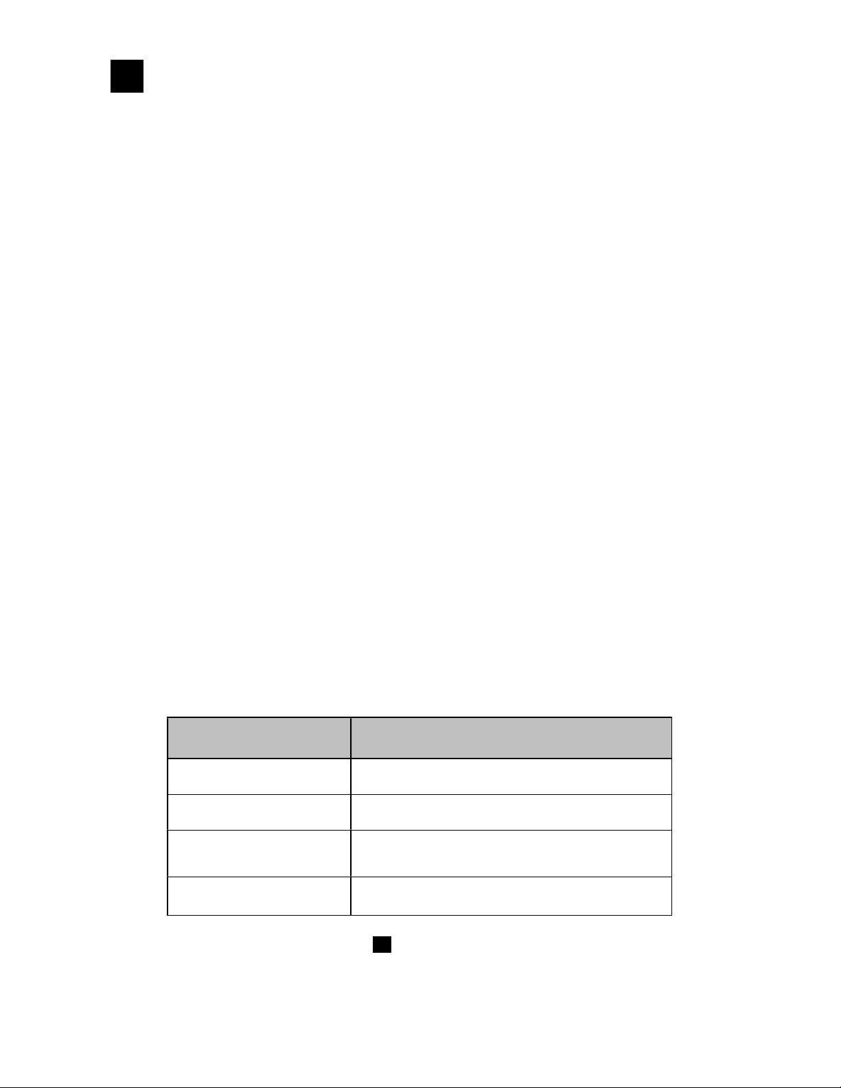
The relation of the MODBUS communications and TCP/IP layers are shown in the table below.
TCP/IP Model Layers
Application layer MODBUS
Transport layer TCP
Internet layer IP, ARP
Main protocols used in
Ethernet communications
Physical layer/Data link layer
For details of the MODBUS protocol, refer to MODBUS protocol.
Hardware (Ethernet)
- 3 -
Page 7
2.2.1 Establishment of TCP connection
R G
F I N
1. SYN
2. SYN+ACK
3. ACK
R G
F I N
G 0
N 1 0 0 1 0
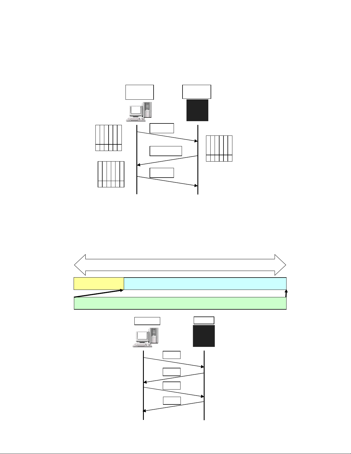
When the upper communications between a PC (the side which requires data: Client) and this unit (the side of
which data is required: Server) is performed, it starts from establishing a TCP connection according to the following
procedures first.
1. The PC transmits the TCP packet with the SYN flag set to this unit.
2. When this unit receives the SYN packet, it transmits the TCP packet the SYN+ACK flags set to the PC.
3. When the PC receives the SYN+ACK packet, it transmits the TCP packet with the ACK flag set to this unit.
PC
Client
U
A
P
C
S
K
H
0
0 0 0 1 0
R
S
S
Y
T
N
U
A
P
R
0
S
C
S
S
Y
K
H
T
N
1 0 0 0 0
This unit
Server
U
A
P
R
S
F
R
C
S
S
Y
I
K
H
T
N
2.2.2 Data transmission and reception through TCP
When the connection is established, transmission and reception of various data through the MODBUS (RTU)
protocol on the TCP data between the PC (Client) side and this unit (Server) are performed.
TCP header
PC
TCP packet
TCP data
MODBUS (RTU) protocol
This unit
Request
Response
Request
Response
-4 -
Page 8
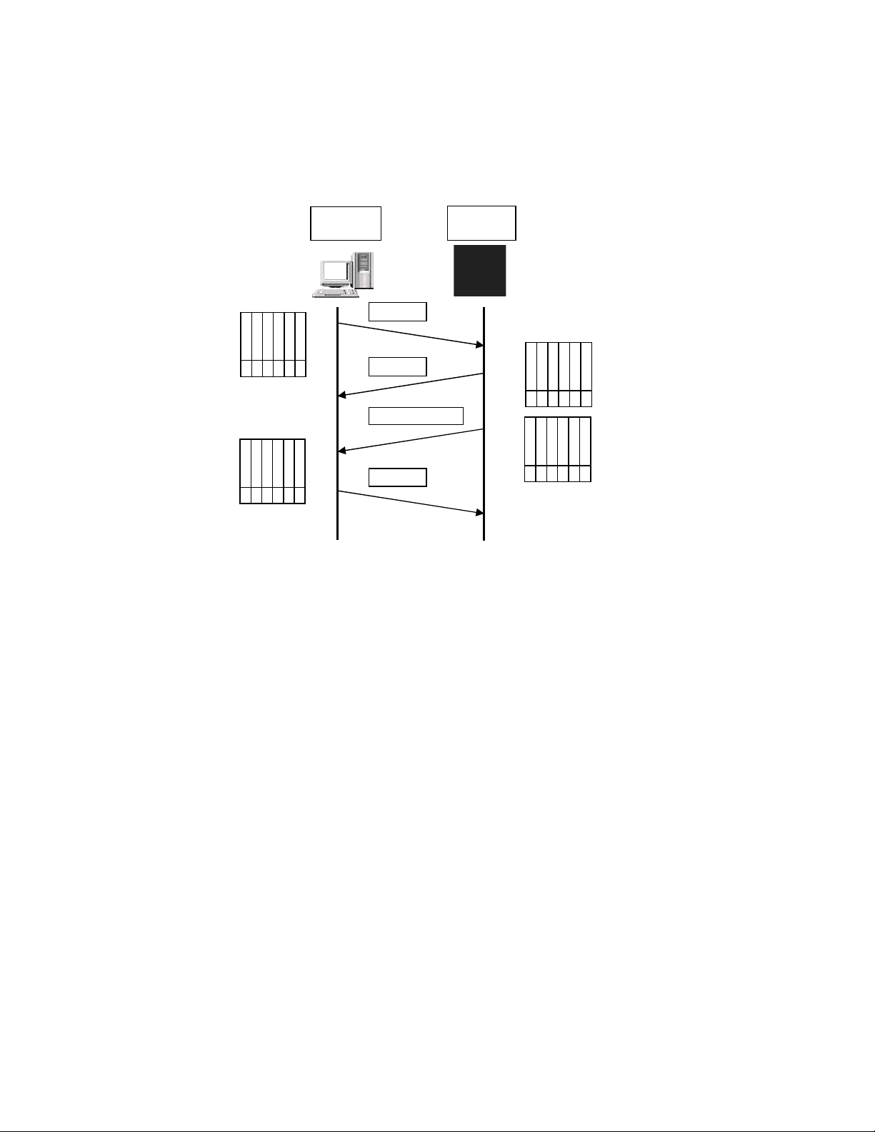
2.2.3 Disconnection of TCP connection
R G
F I N
G 0
N 1 0 0 0 0
R G
G 0
1 0 0 0 0
The communication flow at the disconnection of the TCP connection is as follows.
1. The PC transmits the TCP packet with the FIN flag set to this unit.
2. When this unit receives the FIN packet, it transmits the TCP packet the ACK flag set to the PC.
3. This unit transmits the FIN+ACK packet to the PC.
4. The PC transmits the ACK packet responding to the FIN.
PC
Client
This unit
Server
U
A
P
C
S
K
H
0
0 0 0 0 1
R
S
S
Y
T
N
U
A
P
R
S
R
C
K
F
S
S
Y
I
H
T
N
1. FIN
2. ACK
3. FIN+ACK
4. ACK
U
A
P
R
C
S
K
H
U
A
P
C
S
K
H
0
1 0 0 0 1
R
S
F
S
Y
I
T
N
N
R
S
F
S
Y
I
T
N
N
2.2.4 Functions at communications failure
The followings are functions of this unit when the communications failure on the TCP/IP occurs.
● In case that there is no response from a communication partner (PC, etc.)
When a response (ACK) packet does not return after this unit transmits data to a communication
partner on Ethernet, this unit repeats to retry transmission (up to about 3 minutes).
When there is no response also to the transmission retry packet, this unit disconnects the TCP
connection.
When the communication partner requests to connect the TCP connection to this unit before this unit
disconnect the TCP connection, this unit transmits the RST packet to refuse the connection.
In addition, this unit transmits the RST packet in the following cases.
When this unit receives the TCP packet from other than the partner being connected
When this unit receives the RST packet from the communication partner
●When this unit receives an unexpected reply packet
Fundamentally, this unit ignores the unexpected reply packet. However, this unit disconnects the TCP
connection as soon as it receives the RST packet in case of forcible disconnection of the TCP
connection by the PC side and so on.
-5 -
Page 9
3 . Confirmation of communications
It switches in the state of
485
232C
B
ack side
Switch position
Precaution
3
specifications and settings
3.1 Switch settings
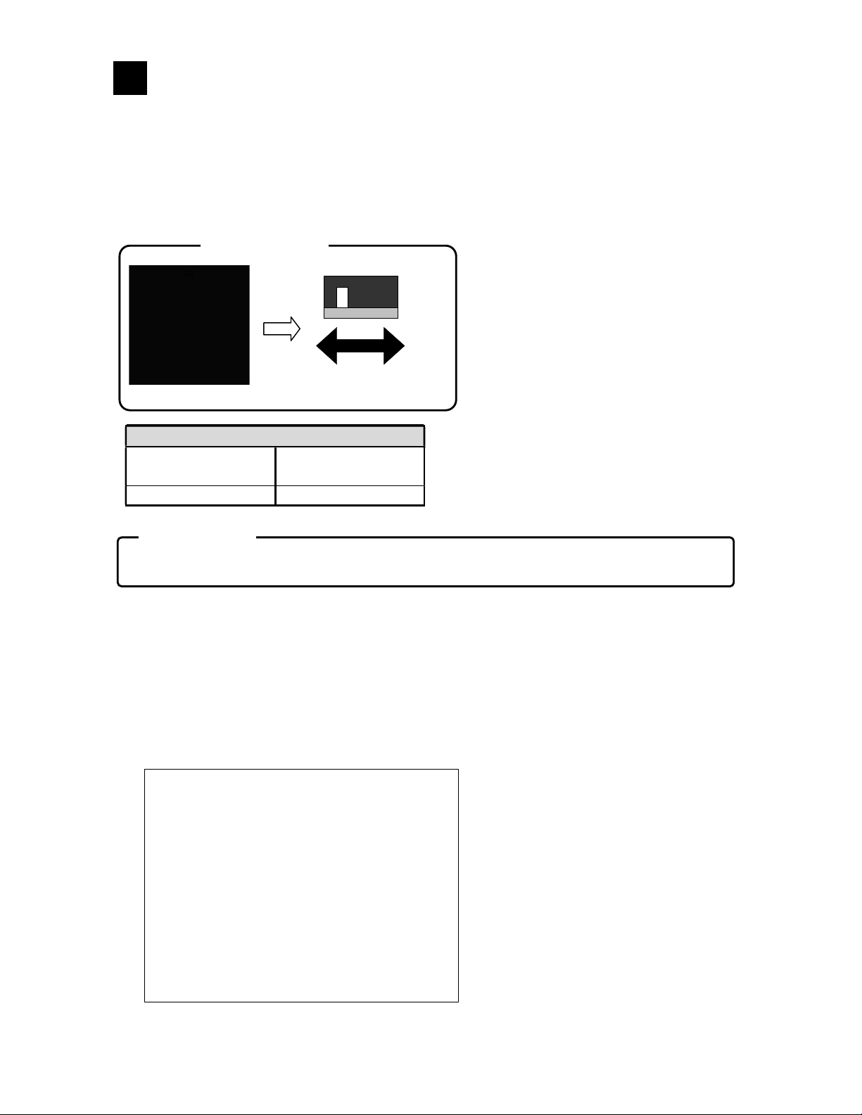
When the serial communication is used, before installations and connections, select the RS-232C or
RS-485 with the selector switch placed the upper part of this unit.
power supply OFF.
SW2
Communication
terminal side
RS-485 RS-232C
Turn the power of this recorder off before the setting of the above switch.
In addition, please confirm that the switch is pushed surely to a side.
Power terminals side
3.2 Settings from this unit
3.2.1 Settings for Ethernet
Push [MENU] key, select [Network settings] from the setting menu displayed, and then press [ENTER]
key. From the menu displayed here, select [Ethernet settings] and push [ENTER] key to display the
setting screen shown below. Set the IP address, the subnet mask and the default gateway if desired. For
the details, refer to “13.10.1 Settings for Ethernet” in the RD9900 General Instruction Manual.
-6 -
Page 10
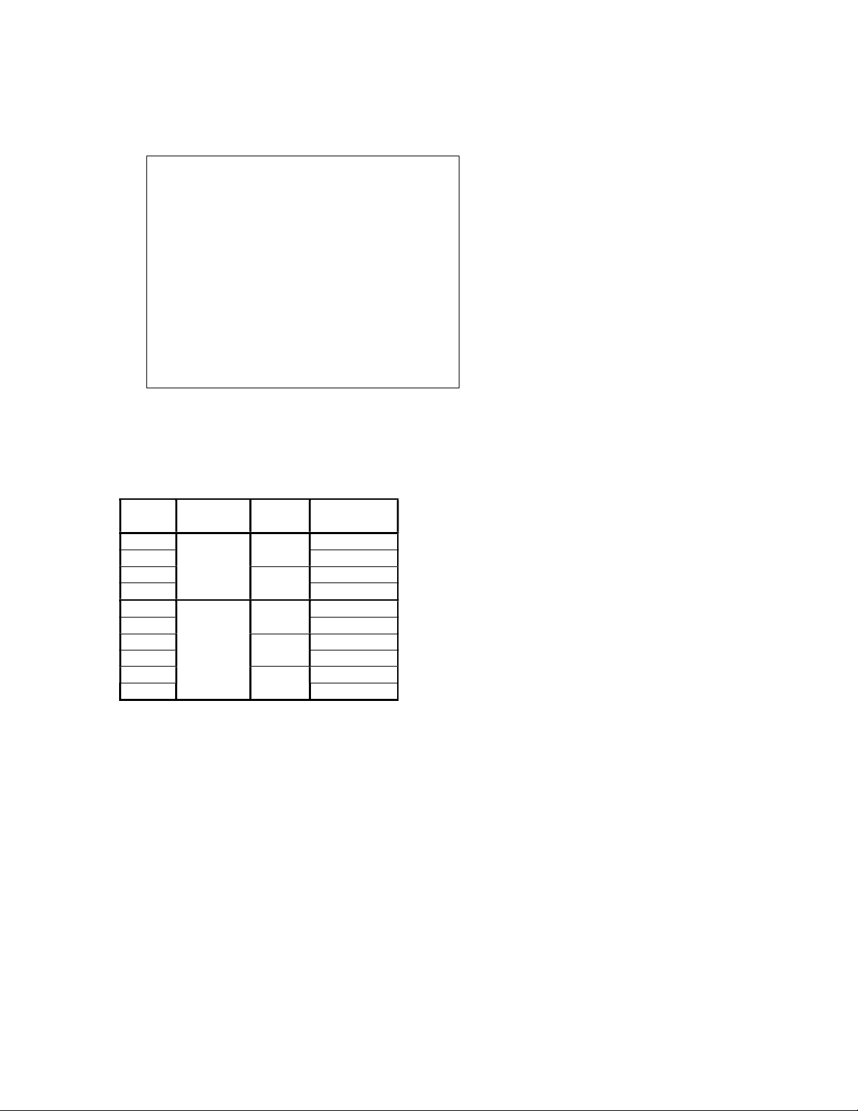
3.2.2 Settings for upper communications
Push [MENU] key, select [System settings] from the setting menu displayed, and then press [ENTER]
key. From the menu displayed here, select [Upper communications] and push [ENTER] key to display
the setting screen shown below. Set each item if desired.
Port number: Specify the port number used in the upper communications* via Ethernet.
Communications mode: Select the RTU/ASCII.
Instrument address: Set an arbitrary number in the range from 01 to 31.
Bit rate: Select 9600bps or 19200bps.
Communications character: Select it from the codes listed below.
Code
7E1
7E2 2
7O1
7O2 2
8N1
8N2 2
8E1
8E2 2
8O1
8O2 2
* In case of the upper communications via Ethernet, the communications mode is the RTU and the
instrument address is fixed at “01”.
Character
length
7 bits
8 bits
Parity
Even
Odd
None
Even
Odd
Stop bit
1
1
1
1
1
-7 -
Page 11
4 . Connections
RD SD
SB SA
4
4.1 Connection precautions
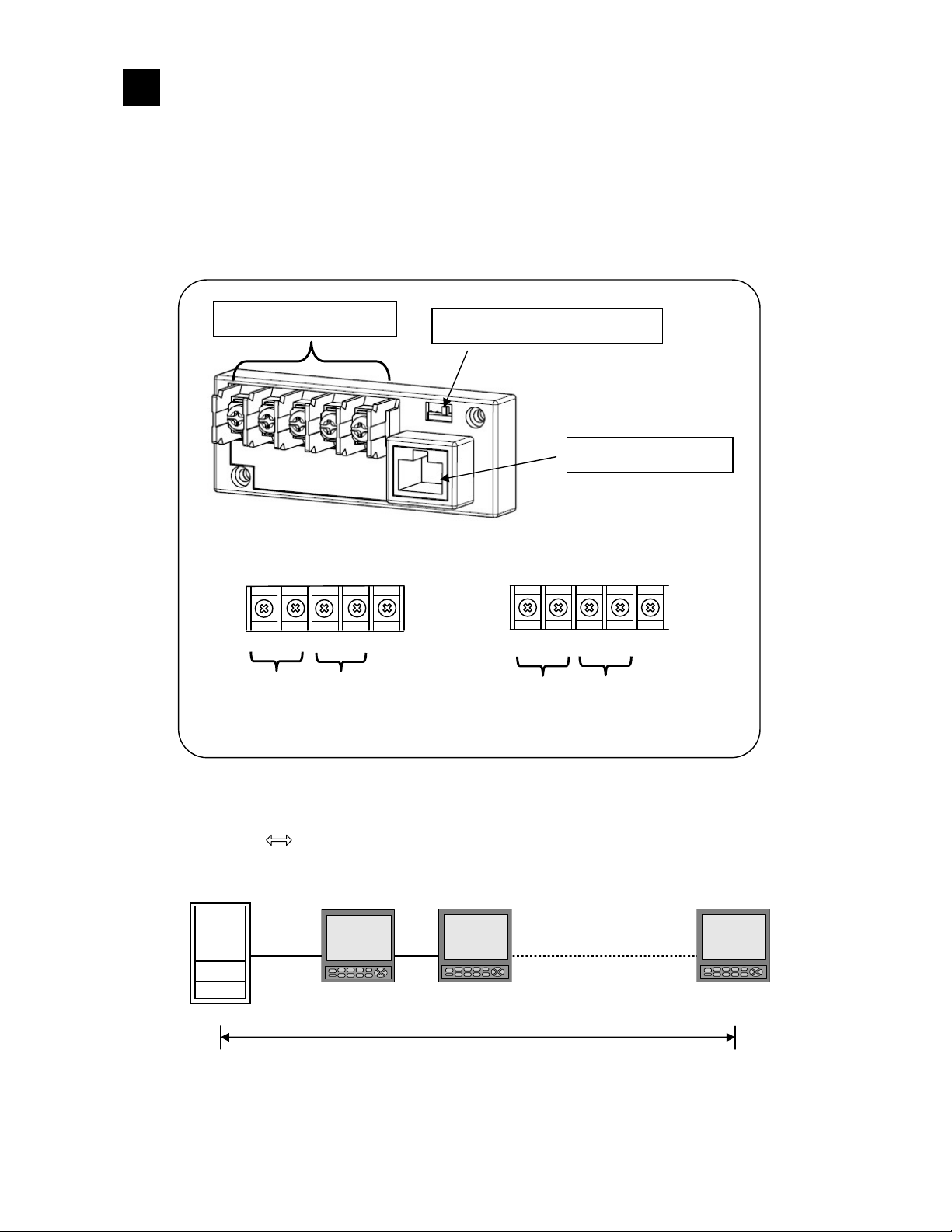
4.1.1 Communications Terminals
In case of the serial communications, the connection terminals are different with each communications interface.
For the details, refer to “4.7 Connections of communications I/F terminals” in the RD9900
Installation/Connection Manual.
4.1.2 Total extension of RS-485 communications cable is up to 1.2km.
The wiring distance between each instrument is arbitrary, but the total extension length of cable is within
1.2km. (Line converter the termination unit of RD9900 series graphic recorders)
Line converter
RS-485/232C terminals
Low-order
High-order
RD9900
SG
RS-485/232C Selector switch
Ethernet connector
SA1
SB1
Low-order
SA2
SB2
High-order
SG
Total extension of cable: Within 1.2km
-8 -
Page 12
4.1.3 Take measures against noise
3.7 or more
Separate the communications cable from power lines and other communications lines more than 50 cm not to be
affected by noise.
In addition, when the communications using a PC or an Ethernet hub are performed, depending on
circumstances, the hub, communications ICs, or the PC itself may be strongly affected by noise and
failures may occur in communication with this unit. In this case, take sufficient measures against noise
for the communication lines, the power lines, etc.
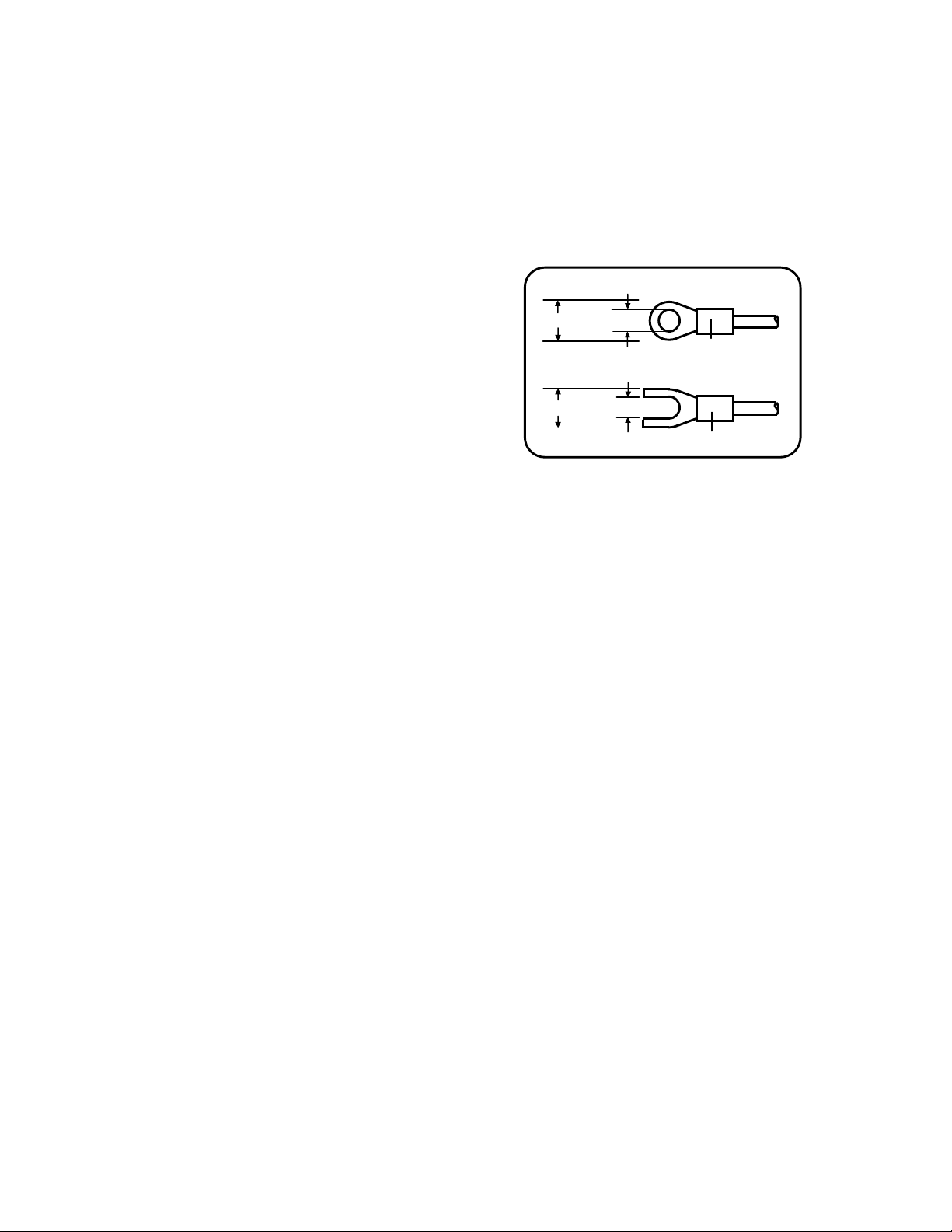
4.1.4 Crimp type terminals
Crimp type ring terminal
Falling off of connections is one of communications failures.
Terminate the communications cable with crimp type ring or
spade terminals with an insulation sleeve. (The terminal
screws of RD9900 series graphic recorders are M4mm and
the terminal screws of the line converter are M3.5mm.)
4.1.5 Attach a termination resistor
8 or less
Insulation sleeve
Crimp type spade terminal
8 or less
(mm)
3.7 or more
Insulation sleeve
For using the RS-485 communications, mount a 100
resistor to the RD9900 series graphic recorder connected at
the final end. (For details, see Section 4.4)
[A general metal film resistor can be used. The resistor (sold separately) is available at OMEGA.]
However, there are also environments where a communication error cannot take place easily without the
termination resistor attached
4.1.6 Number of this unit connectable
For RS-232C:
For RS-485: Up to 31 sets* including other RS-485-compatible instruments
* ICs complying with the RS-485 standards are used in this unit, but the number of the units that can
communicate in high quality is different by cables used, distance and types of instruments connected.
1 set
-9 -
Page 13
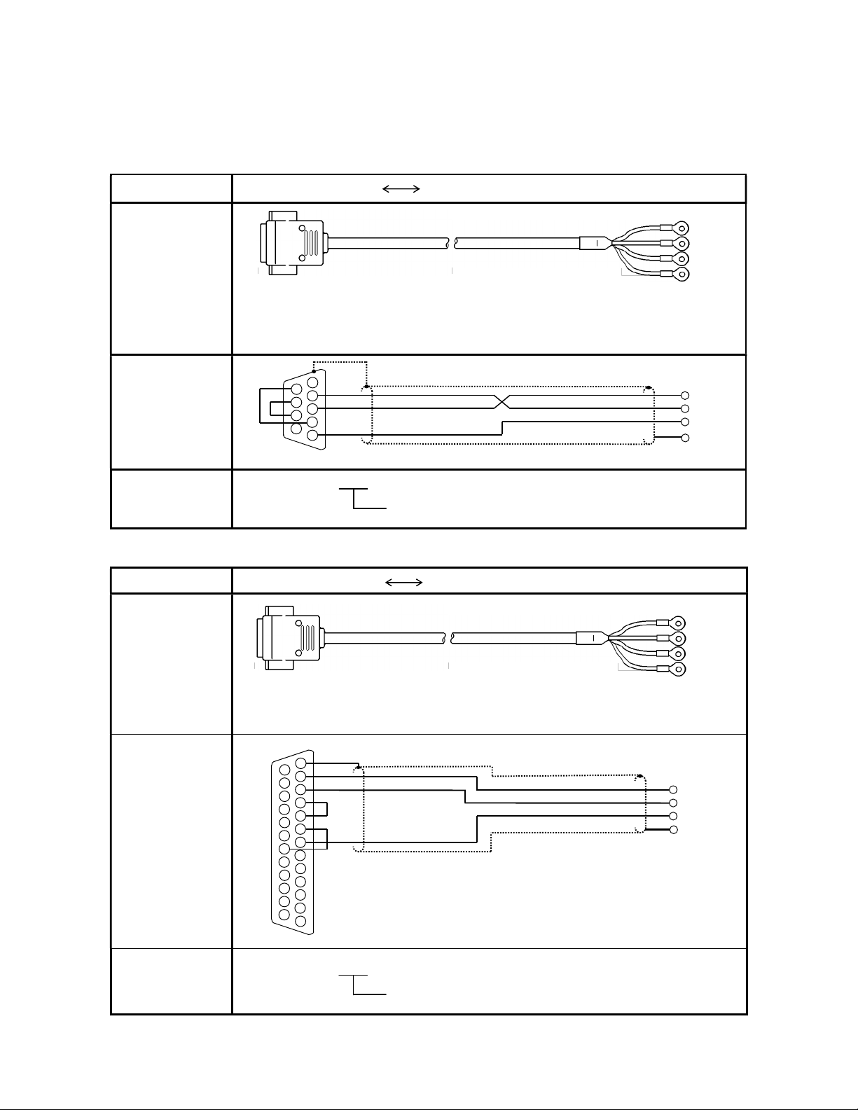
4.2 Communications cables
SD
RD
SG
2 3
5
7 8
RD SD SG
recorder or a line converter
2 3
5 6
8 9
11 12
15 16
18 19
21 22
24 25
RS-232C cable (max. length: 15m)
SG
SD RD SG
FG
FG
FG
FG
Use communications dedicated cables. Communications dedicated cables (sold separately) are available at
OMEGA.
4.2.1 Communications cables for RS-232C
(1) Connections between a PC (9 pins) and the RD9900 series recorder, and between a PC (9 pins) and a line converter
Cable
9-pin connector RS-232C cable with crimp type ring terminals
Shape
Internal wiring
9-pin connector
for a PC
6
9
1
4
RS-232C cable (max. length: 15m)
Terminals for the KR2000 series
RZ-CRS6
Type code
(2) Connections between a PC (25 pins) and the RD9900 series recorder, and between a PC (25 pins) and a line converter
Cable
Shape
Cable length: 1~ 15m (to be specified)
25-pin connector RS-232C cable with crimp type ring terminals
RD
SD
Internal wiring
Type code
25-pin connector
for a PC
Terminals for the KR2000 series
recorder or a line converter
1
14
4
17
7
20
10
23
13
For NEC’s PC98 series (except NX)
RZ-CRS2
Cable length: 1 ~ 15m (to be specified)
-10 -
Page 14
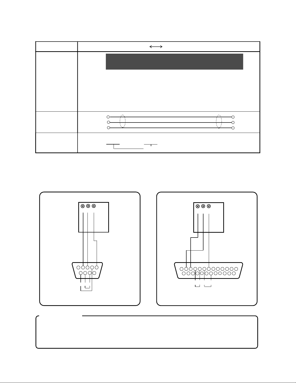
4.2.2 Communications cables for RS-485
R
D9900
:
SA SB SG
SASBSGSA SB SG
RDA
RDBSGSA SB SG
SBSA
SG
RDA
RDB
SG
5 6 7
9 10 11 12 13 14 15
19 20 21 22 23 24
CS DR ER
ER
2 3 4 6 7 8
Connections between a line converter and the RD9900 series recorder, and between the RD9900 recorder and
the RD9900 recorder
Cable
Crimp type ring terminals RS-485 with crimp type ring terminals
Shape
Line converter: RDA RDB SG
RD9900
The cable consists of a twisted dual-core CVVS wires with SG (signal
grounding) wire at both ends. As the line converter has no SG terminal, cut this
wire to use.
Internal wiring
Type code
RZ-LEC or RZ-CSS
Cable length: 1 ~ 200m (to be specified)
4.3 Connection of High order communication RS-232C
This unit uses three control signals of Send (SD), Receive (RD), Signal ground (SG) only. Since regular
PCs are controlled by control signals, the PCs do not function by only connecting three signal cables
without wiring processing inside the connector. The wiring processing depends upon the control signals
being controlled by the PC. For details, read the manual for the PC used.
[Connection
example 1]
RD9900
SD
RD
SG
Communications
cable
RZ-CRS6
1
9-pin connector for a PC
(PC-98 series/IBM-PC・AT)
5
9
RS DR
CS
[Connection
example 2]
1
RD9900
SD
RD SG
Communications
cable
RZ-CRS2
4
3
2
17 18
16
RS
25-pin connector for a PC
(PC-98 series)
8
25
Precaution
The length of the RS-232C cable is maximum 15m. The connection example 1 is for the 9-pin
connector and the connection example 2 is for the 25-pin connector.
Don’t connect the SG line to the protective conductor terminal (ground terminal).
-11 -
Page 15
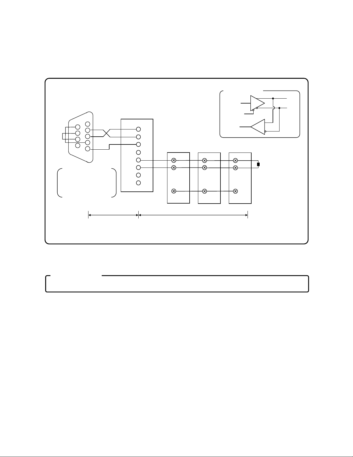
4.4 Connection of High order communication RS-485
SD FR
RS
2
3
4
5
6 7 8
9
SD SG
3
5 6
8
Transmission
SA
Precaution
This paragraph describes the connections of the RS-485 communications interface to a PC via the line
converter (Model SC8-10: sold separately). Since the line converter and the PC use three control signals of
Send, Receive and Signal ground only, the wiring processing inside the connector is required in the same
way as in RS-232C connections.
[For details, read the manual for the line converter (Model SC8-10: sold separately).]
(9 pins or 25 pins)*
The above figure
shows the example
of the 9-pin
connector.
DR
CS
PC
RD
SG
1
Within 15m
Line converter
(SC8-10)
RD
1
2
4
RDA
RDB
SDA
7
SDB
Total length: Within 1.2km (max. 31 sets)
This unit 1
SA
SB
SG
This unit 1
SA
SB
SG
Internal circuit
data
Receive
data
This unit 1
SA
SB
SG
SB
Termination
resistor
100Ω 1/4W
* For the wiring processing of the connector, refer to Para. 4.3 RS-232C connections.
Don’t connect the SG line to the protective conductor terminal (ground terminal).
-12 -
Page 16
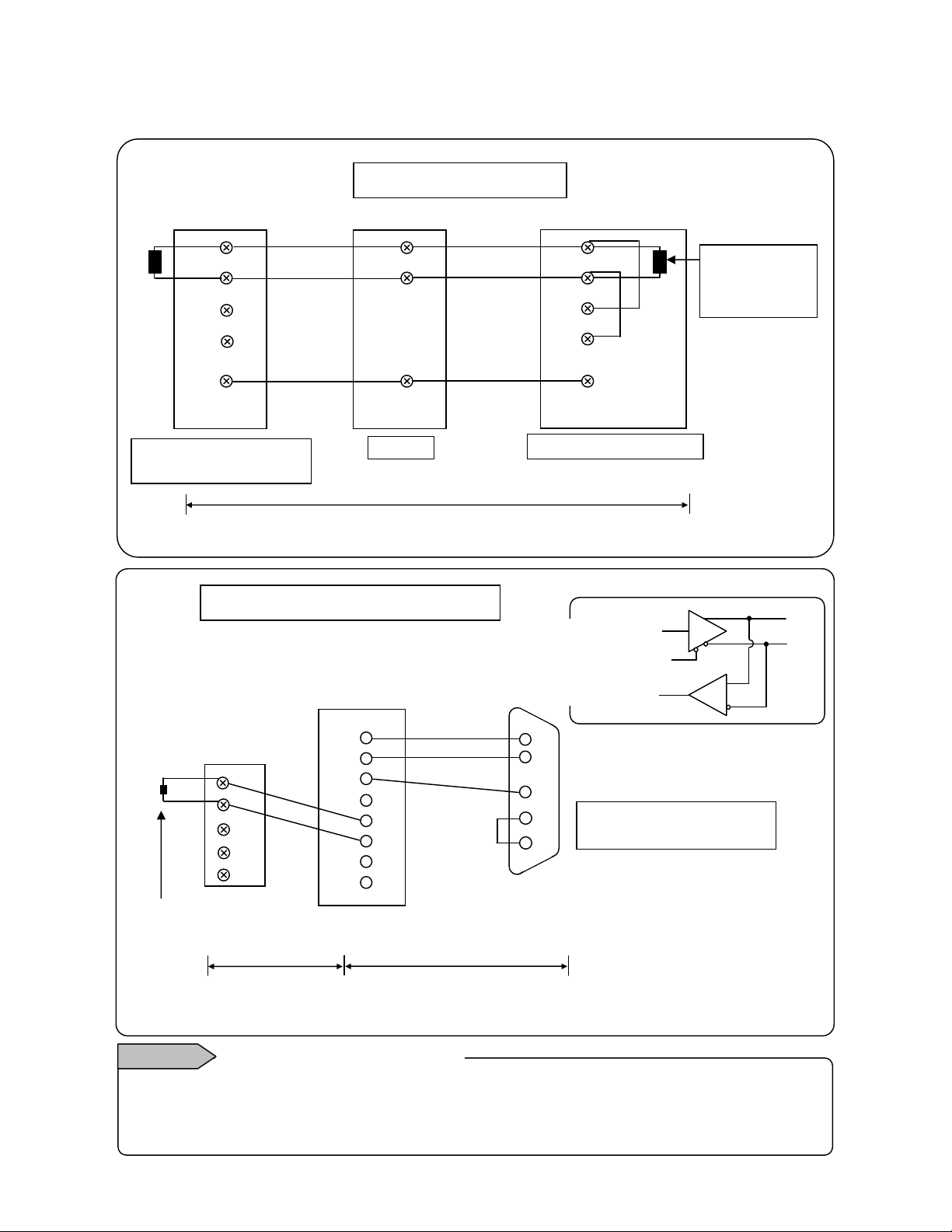
4.5 Connection of Low order communication RS-485
AL/AH
SA
SD SG
2 3
5 6
8
SD SG
3
Transmitting
circuit
data
Connect SA1, SB1 of RD9900 and SA, SB of low order connected instrument like the following figure.
Refer to instruction manual of each instrument for detail method of low order instrument connection.
SA1
SB1
SA2
SB2
SG
RD9900 Low order
communications terminal
Example of connection 1
SB
SG
SE3000 , MELSEC etc.
Within 1.2km(max. 31 sets)
Communications cables
RZ-LEC0□□,RZ-CSS1□□
SDA
SDB
RDA
RDB
SG
Termination
resistor
100Ω・1/4W
Terminatio
n resistor
Example of connection 2 (SYSMAC)
RS-485
This recorder
SA1
SB1
SA2
SB2
SG
100Ω・
Within 1.2km
Communications cables
RZ-LEC0□□,RZ-CSS1□□
Protocol converter
(SC8-10)
1
RD
4
RDA
RDB
7
SDA
SDB
Communications cables
RS-232C
(D-SUB 9-pin receptacle)
Within 15m
RZ-CRS6□□
data
Internal
Receiving
2
RD
9
4
RS
5
CS
Connecting the RS and CS.
Other open.
SYSMAC CPU unit
Internal RS-232C port
SA
SB
Remarks
Mounting termination resistor
To ensure the transmission of data via RS-485 communications, mount a termination resistor at both
ends of transmission lines. When the protocol converter (SC-8) is at an end of a transmission circuit,
short the terminals of and of the unit to insert the termination resistor automatically.
-13 -
Page 17

5 . MODBUS protocol
Precautions
5
Precautions and basic procedure of communications
1. As the control signal wire is not used, pay attention to retransmit a command.
The serial interface of this instrument communicates without using control wire.
Pay attention to retransmit a command as reception defects may occur depending on
the status of this instrument.
2. Do not remove any devices or communication cables and do not turn ON or OFF
the power supply during communications.
If devices or cables configuring the serial interface are removed or if the power is
turned ON (OFF) during communications, the communications may stop or an error
may occur. If this happens, reset all the devices configuring the serial interface and
restart the communications from the beginning.
3. Transmit the next command after confirming that the communication drive is
switched OFF.
In RS-485, if multiple instruments are connected to same communications line, then
only 1 instrument, of which instrument number is specified from the PC, drives the
communications line. At that time, for transmitting all the characters to the PC
completely, the drive of the communications line is turned OFF with some time interval
after the last character is sent. If the PC transmits a command to the next instrument
before it becomes OFF, then the signal crashes and normal communications cannot be
done. Therefore take care when a high speed PC is used. This interval is around 5ms.
-14 -
Page 18
5.1 Transmission mode of message
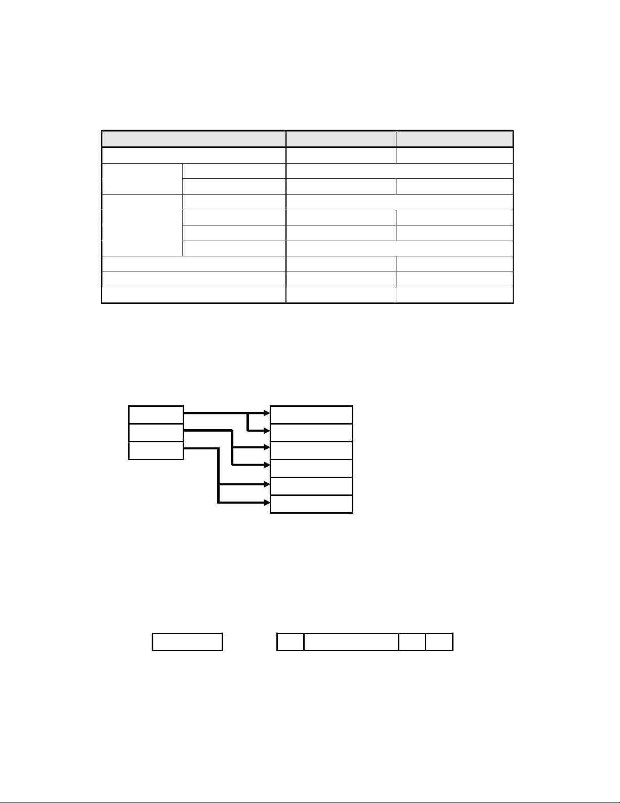
There are 2 types of the RTU (Remote Terminal Unit) mode and the ASCII mode.
(Table 1. Comparison of RTU mode and ASCII mode)
Item RTU mode ASCII mode
Transmission code Binary ASCII
Error detection
(Error check)
Character
configuration
Message start code None : (Colon)
Message end code None CR, LF
Data time interval Less than 28-bit hours Less than 1 second
(Note) When the data bit is 7 bits, [Parity bit None] is not applicable.
Vertical direction Parity
Horizontal direction CRC-16 LRC
Start bit 1 bit
Data bit 8 bits 7 bits, 8 bits
Parity bit
Stop bit 1, 2 bits
None, odd, even
None (Note), odd, even
5.1.1 Transmission data
The RTU mode is binary transmission. The ASCII mode divides 8 bits binary of the RTU into higher 4 bits and lower
4 bits and converts into characters respectively (0-9, A-F).
Ex) RTU mode
67H
The RTU mode is half in the message length as compared to the ASCII mode and enables the efficient transmission.
89H
ABH
ASCII mode
36H (“6”)
37H (“7”)
38H (“8”)
39H (“9”)
41H (“A”)
42H (“B”)
5.1.2 Message frame configuration
The RTU mode is configured by message parts only.
The ASCII mode is configured by the start character “: (colon, 3AH)”, messages and the end character “CR (carriage
return, ODH) + LF (Line feed, OAH)”.
RTU mode ASCII mode
Message : Message CR LF
As the ASCII mode has the start character of “:” it has an advantage that the troubleshooting is easy.
-15 -
Page 19
5.2 Data time interval
RTU mode: Less than 28-bit hours (2.8msec at 9600bps, 1.4msec at19200bps)
ASCII mode: Less than 1 second
When a message is sent, be careful that the time interval of data configuring one message does not exceed the time
shown above. If the time interval exceeds the time shown above, the receiving side (this unit) judges that the
transmission from a sender is finished and the data are processed as the reception of an abnormal message.
In the RTU mode, message characters should be sent continuously, but in the ASCII mode, as the interval between
the characters is maximum 1 second, a master (PC) whose processing speed is comparatively slow can be used.
5.3 Message configuration
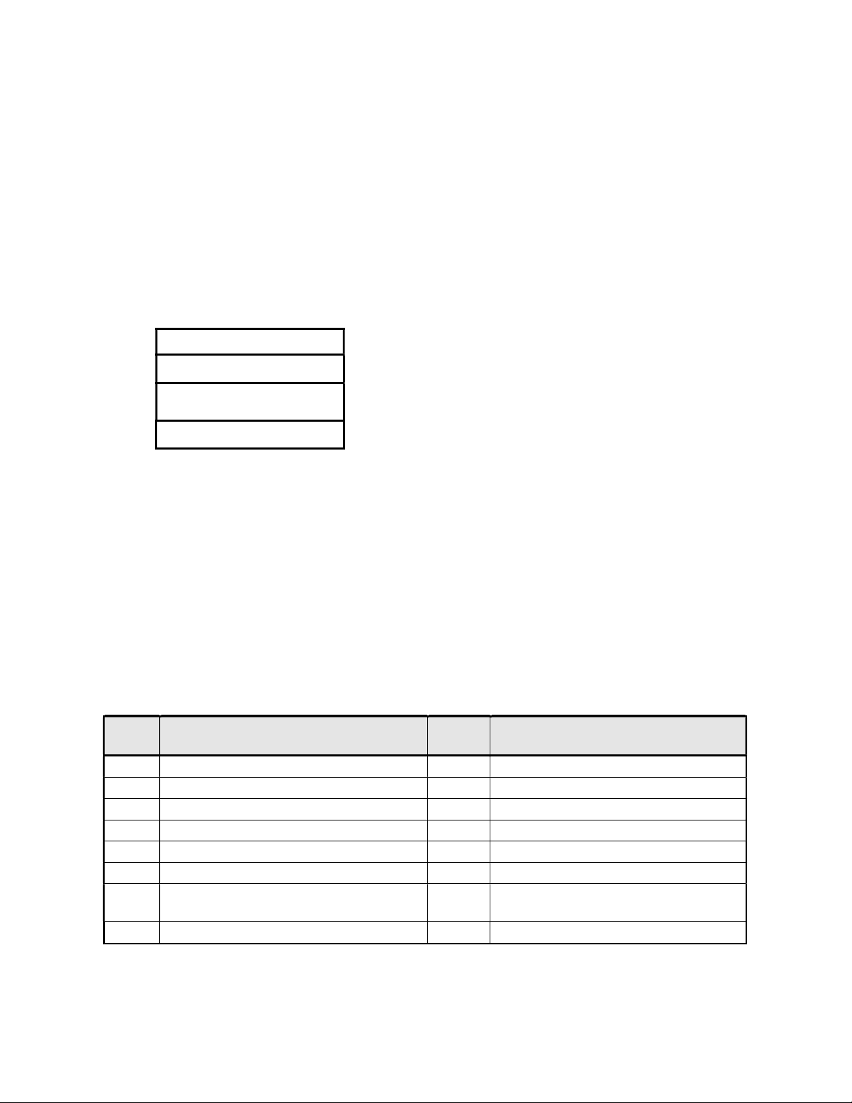
The MODBUS messages have the following configuration for both of the RTU mode and the ASCII mode.
Slave address
Function code
Data
Error check
5.3.1 Slave address
Slave addresses should be set in advance in a range of 1-31. The master usually communicates with 1 slave. Only
the slave corresponding with the slave address in the command message from the master responds to that
message.
The slave address “0” is used in messages (Broadcast) to all the slaves from the master. In this case, the slaves do
not return any response.
5.3.2 Function code
The function codes are the codes to be performed in the slaves and each data is roughly categorized as follows. The
table shows original functions of MODBUS and functions of our MODBUS instruments.
(Table 2. Function codes)
Code
Function Unit
01 Reading of digital (ON/OFF) setting value
02 Reading of digital input data
03 Reading of analog setting value
04 Reading of analog input data
05 Writing digital setting value
06 Writing analog setting value
Transmission of received data (for
08
diagnosis)
16 Writing multiple analog setting values
1 bit
1 bit
16 bits
16 bits
1 bit
16 bits
MODBUS original function
(Reference)
Reading the status of coil
Reading the status of input relay
Reading the content of holding register
Reading the content of input register
Changing the status of single coil
Writing to single holding register
Loop back test
Writing to multiple holding registers
-16 -
Page 20
1. Digital settings value
2. Digital input data Data of event activation status etc.
3. Analog settings value
4. Analog input data
* For the details, refer to the reference table.
Parameters to change functions including record ON/OFF, marker text record
etc.
Various setting information.
Numeric values are in the range of 16 bits (-32763 to 32767).
Measurement data, instrument specification information etc.
Numeric values in the range of 16 bits are outputted.
5.3.3 Data part
Data structures differ depending on the function codes. In case of requests from the master, they are configured by a
code number (relative numbers calculated from reference numbers mentioned hereafter) of the target data for
reading/writing and number of data, etc. Responses from the slaves are configured by data requested by a
command etc.
All basic data of MODBUS are 16-bit integers and existence of a mark is decided for each data. Therefore real
values of data like measured values are expressed by allocating a decimal place to a different address or by
normalizing with high/low values of a scale while the decimal place is fixed. This instrument adopts the allocation
method of the decimal place to a different address.
In the data part, there are specific numeric values such as input data allocated as error data. When using such
data, perform the error judgment of data first and then combine them with decimal point data.
If such error data are combined with decimal point data first, they are judged as normal data.
Precaution
5.3.4 Reference number
Numbers called “Reference numbers” are allocated to all the data of this instrument and these numbers are
necessary for reading/writing data.
The data are classified into “Digital setting values”, “Digital input data”, “Analog input data” and “Analog setting
values” depending on their types. Number designation in messages is performed by relative numbers corresponding
to the respective reference numbers.
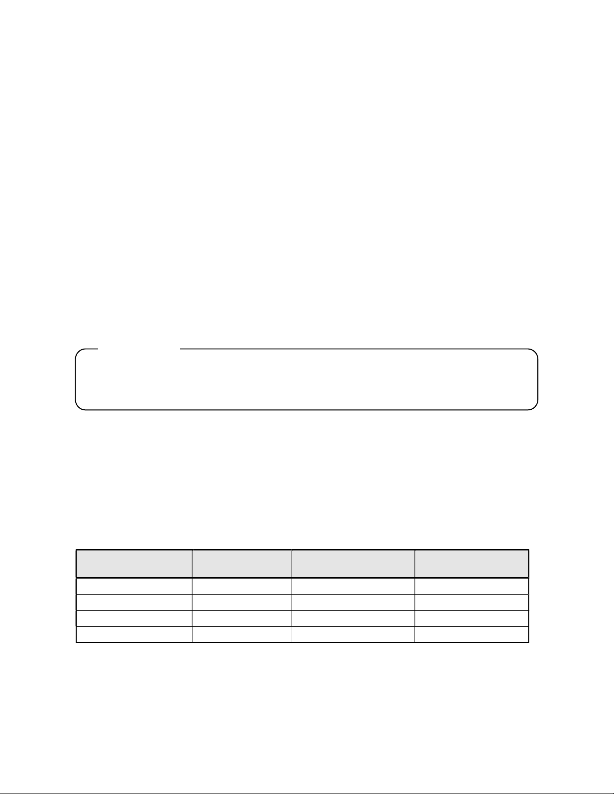
(Table 3. Reference numbers and relative numbers)
Data type Reference number Relative number
Digital setting value 1 ~ 10000 Reference number - 1
Digital input data 10001 ~ 20000 Reference number - 10001 Input relay
Analog input data 30001 ~ 40000 Reference number - 30001 Input register
Analog setting value 40001 ~ 50000 Reference number - 40001 Hold register
For example, the relative number of “Reference number 30101 (Data of Channel 1)” mentioned later
becomes “100”.
MODBUS original
(Reference)
Coil
-17 -
Page 21

(Table 4. Reference numbers)
Data type Parameter
Digital setting value
Key lock
Record ON/OFF
Marker text writing
Reference
number
1 ~ 20
Corresponding
function code
01 (READ)
05 (WRITE)
Reference
table
Para. 5.7.1
Digital input data
Analog input data
Analog setting value
Event status
Instrument information
Measurement data
Common parameter
(Date/time, upper
communications, processing
reset etc.)
Setting parameter for each
channel
Communications parameter
Low order communications
parameter
Group parameter
Common parameter (screen,
schedule etc.)
File-related-parameter
Marker text
Low order communication
setting (PLC relation)
Web server setting
10101 ~ 10800 02 (READ)
30001 ~ 30093
30101 ~ 30188
40001 ~ 40098
40102 ~ 44500
45001 ~ 45486
45501 ~ 45544
46001 ~ 46500
47110 ~ 47167
47207 ~ 47700
48001 ~ 48752
48951~48985
49001~49064
04 (READ)
03 (READ)
06 (WRITE)
16 (WRITE)
Para. 5.7.2
Para. 5.7.3
Para. 5.7.4
-18 -
Page 22

5.3.5 Error check
The error check of transmission frame differs depending on the mode.
RTU mode: CRC-16
ASCII mode: LRC
5.3.5.1 Calculation of CRC-16
The CRC method divides the information to be sent by a generating polynomial and transmits it by attaching the
calculated remainder to its end. The generating polynomial is as follows.
1 + X2 + X
The following calculation is performed for information from a slave address to the end of data.
1) Initialization (=FFFFH) of data of CRC-16 (consider as X)
2) Exclusive OR of data 1 and X (EX-OR) → X
3) 1-bit shifting of X to the right → X
4) For a carry existed, A001H and EX-OR are taken, else go to 5). → X
5) 3) and 4) are repeated up to 8-time shifts.
6) EX-OR of the following data and X→ X
7) Same as 3) - 5)
8) Repeating up to the last data.
9) A message is created in the order from lower digits to higher digits of the calculated 16-bit data (X).
Example)
When data is 02H 07H, the CRC becomes 1241H.
Then the error check data becomes 41H 12H.
15
+ X16
- 19 -
Page 23

Reference: CRC-16 calculation program (C language)
/***** CRC-16 calculation program *****/
#include <stdio.h>
#include <conio.h>
void main(void){
/*** Internal variable declaration ***/
unsigned int iLoopCnt; /* Loop counter */
unsigned short usData; /* Input data */
unsigned short usCrcData; /* CRC-16 data */
unsigned short usErrChkData; /* Error check data */
int iDummy; /* Dummy variable */
/* (1) Initialization of output result of a CRC-16 data */
usCrcData = 0xffff;
printf("Enter the hexadecimal data (Cancel by [q].) >\n");
while( scanf("%x", &usData) != 0){
/* (2) (6) Taking exclusive OR of the CRC output result and the entered data */
usCrcData = usData ^ usCrcData;
/*** CRC calculation processing ***/
/* (5) Repetition up to 8-bit shifts */
for(iLoopCnt = 0 ; iLoopCnt < 8 ; iLoopCnt++){
/* (4) Checking if there is a carry. */
if(usCrcData & 0x0001){
/* (4) At a carry activated */
/* (3) 1-bit shifting of the CRC output result to the right */
usCrcData = usCrcData >> 1;
/* (4) Taking exclusive OR with A001H */
usCrcData = usCrcData ^ 0xa001;
}else{
/* (4) At a carry no activated */
/* (3) 1-bit shifting of the CRC output result to the right */
usCrcData = usCrcData >> 1;
}
} /* for */
}; /* while */
printf("The CRC-16 data is %xH.", usCrcData);
/* Error check data creation*/
usErrChkData = (usCrcData >> 8) | (usCrcData << 8);
printf("The data for the error check is %xH.", usErrChkData);
iDummy = getch();
}
- 20 -
Page 24
5.3.5.2 LRC calculation method
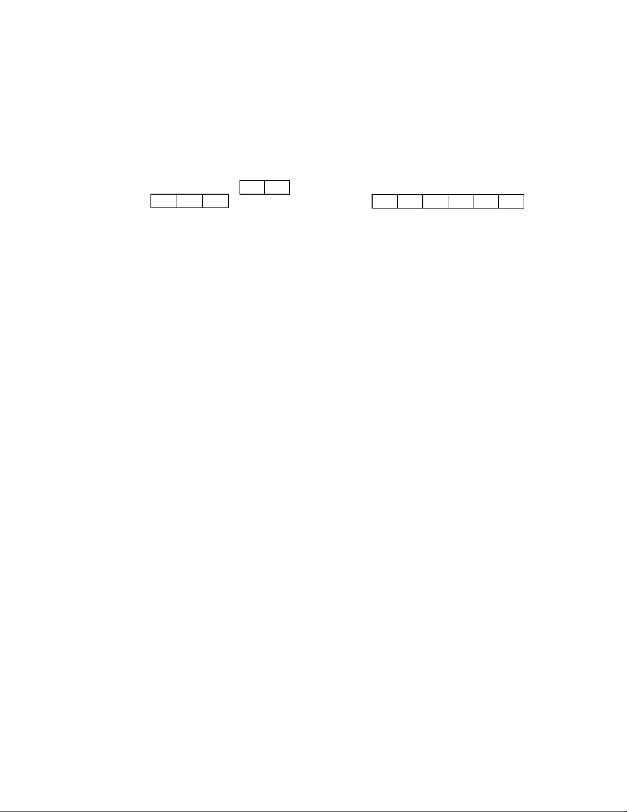
The data from a slave address up to the end of the data are calculated by the following procedure.
1) A message is created in the RTU mode.
2) The data from the start (slave address) to the end are added. →X
3) The complement (Bit inversion) of X is taken. →X
4) 1 is added. (X=X+1)
5) X is attached at the end of the message as the LRC.
6) The entire data is converted into the ASCII character.
Example) When the data is 02H 07H , the LRC becomes F7H. Therefore the binary message
becomes 02H 07H F7H and the ASCII message becomes 30H 32H 30H 37H 46H 37H
5.3.6 Precautions at the time of data processing
1) As the measurement data and the decimal place are assigned to different numbers, it is necessary to
use both information at replaying the data.
2) As each 1 data can be accessed (changed), precautions are necessary at the time of setting the
associated data including Initialization process of the associated data due to change of a range
number, etc.
3) Read and write the data in the range stipulated by the reference number. Reading and writing of
reference number not stipulated may have an adverse effect on the instrument operation.
4) At the reading of continuous reference numbers, the data of the reference number not stipulated
becomes “0”.
5) At the writing to continuous reference numbers, if error is detected, all the settings become disabled.
- 21 -
Page 25
02H
[:]
00H
02H
CR
5.4 Message creation
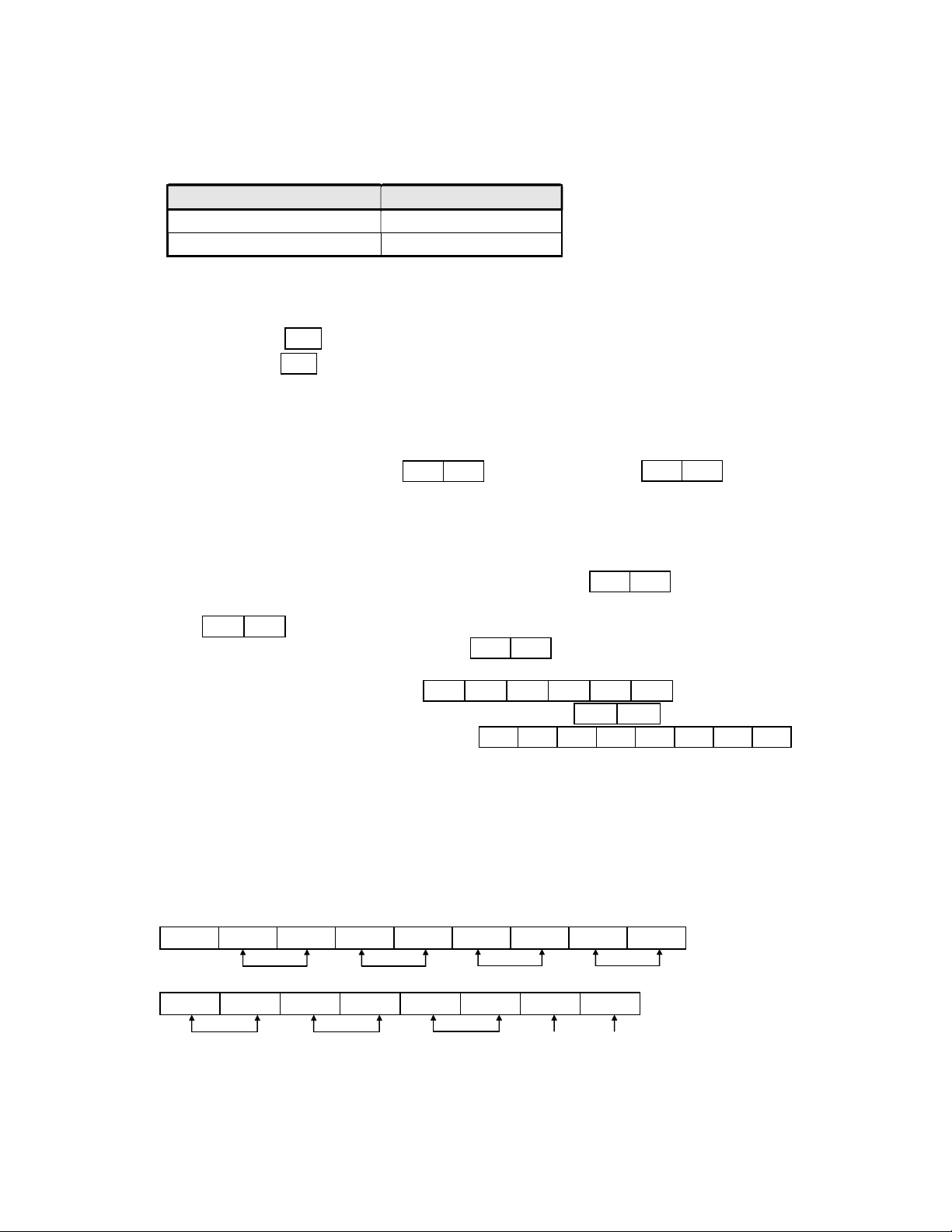
A message is consisted of 1) Slave address, 2) Function code, 3) Data part and 4) Error check code. (Refer to
“5.3 Message configuration“)
The number of data that can be read once is within the following range.
Transmission mode Number of data
RTU 120
ASCII 120
The creating method of a message is explained in the following example.
Example) Reading of the measurement data of “Channel 1” of this unit set by the “Slave address 02”.
5.4.1 RTU mode message
1) Slave address: 02 ( 02H )
2) Function code: 04 ( 04H )
t is the reading of the analog input data (contents of input register). When the function code is “04”, it is
necessary to specify “Relative number of data 2 bytes” for reading in the data part and “Number of data 2
byte” for reading. (Refer to “5.3 Message configuration”. Refer to “5.3.2 Function code: 04”.)
* It is necessary to confirm the number of bytes of data.
3) Data part: Starting relative number 100 ( 00H 64H ) , Number of data 2 ( 00H 02H )
The measured data (analog input data) is stored in the reference number 0001 to 40000. (Refer to “5.3.4
Reference number Table 3”). By the reference table, you will understand that the integer part of CH1 is stored
in “30101” and the decimal place is stored in "30102". (Refer to “5.7 Reference table“. and refer to “5.7.3
Analog input data” for reading of measured data.) The relative number of the starting “Reference number
30101” is 30101-30001=100. If it is expressed in 2 bytes, it becomes “ 00H 64H “. The number of data to
be read is the integer part of CH 1 and the decimal place and if it is expressed in the hexadecimal 2 bytes, it
becomes “ 00H 02H “.
4) Error check: Calculation by the CRC-16 2730H ( 30H 27H )
The error check in RTU mode is performed by the CRC-16. (Refer to “5.3.5.1 Calculation of CRC-16“) The
data of basic part of the message becomes 02H 04H 00H 64H 00H 02H as per 1) to 3), and the
CRC-16 becomes 2730H. Therefore the error check data becomes 30H 27H .
5) Message: A message is created with the configuration of 02H 04H 00H 64H 00H 02H 30H 27H .
(Refer to “5.3 Message configuration”)
5.4.2 ASCII mode message
The error check LRC is calculated from basic part of the message. The LRC becomes 94H. (Refer to “5.3.5.2
LRC calculation method). Each data of the basic part is converted into the ASCII code. In addition, the LRC is
converted into ASCII code and is attached to the basic part. The start character of the message " : ", and “CR”
and “LF” are added to the end.
(Example) In case of 02H, 04H, 00H, 64H, 00H, 02H, 30H and 27H
3AH 30H 32H 30H 34H 30H 30H 36H 34H
30H 30H 30H 32H 39H 34H 0DH 0AH
00H 64H
94H
LRC
- 22 -
LF
Page 26
(00H)
(02H)
5.5 Function Code
The response for each function is given below. (Refer to <Table 2 Function code table> in “5.3.2 Function code“)
Note) Refer to “5.6 Process during abnormality“ for responses for abnormality.
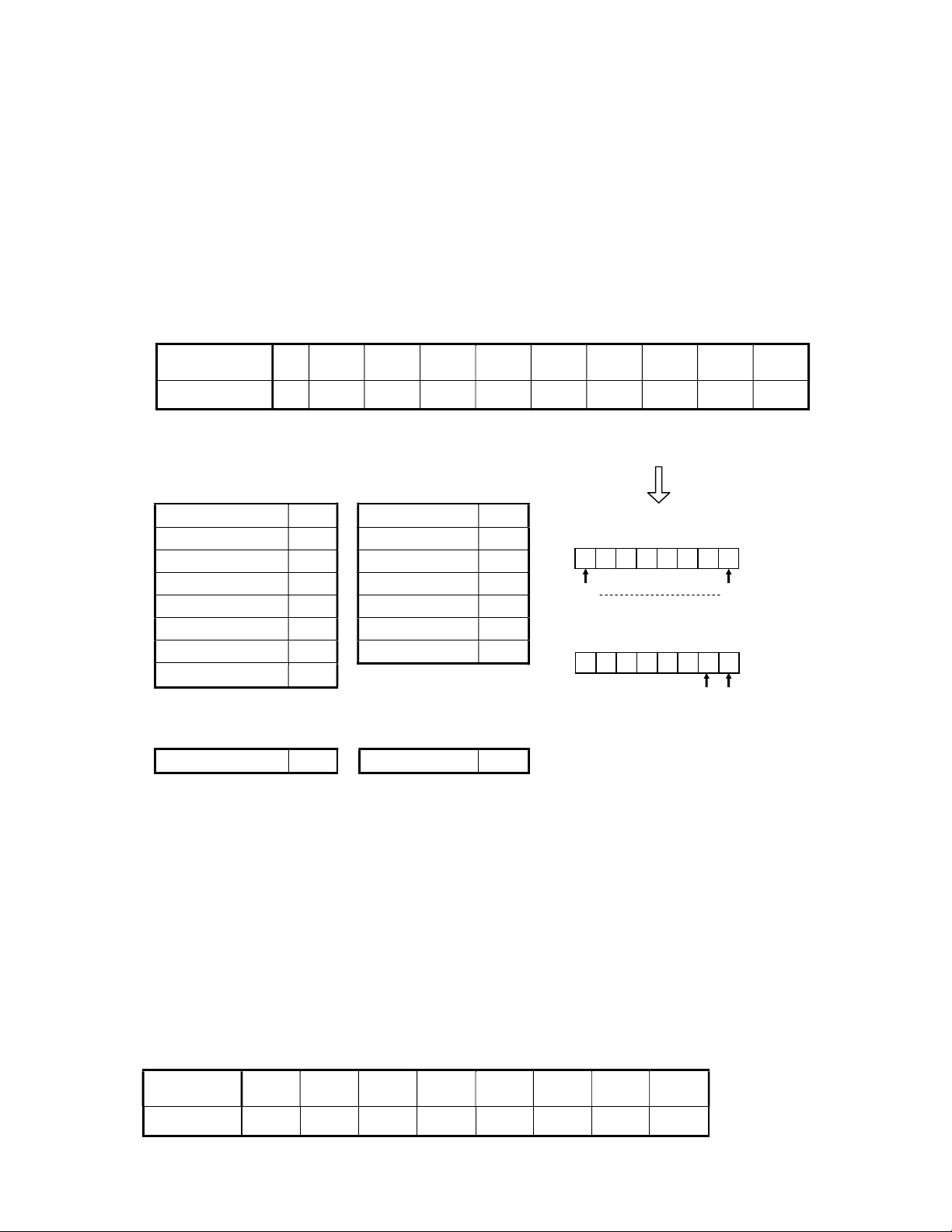
5.5.1 Reading of digital setting values (Reading of coil status)
[Function code:01 (01H)]
“Digital (ON/OFF) setting values with the continuous numbers” are read for the number of data specified from
the start number specified. The ON/OFF data is arranged per 8 by 8 in numerical order in 1 data (1 byte) and
configures a data of the response message. The LSB (D0 side) of each data is the digital data of the youngest
number. When the number of read data pieces is not in multiples of 8, the unnecessary bits become 0.
Example) Reading of 10 digital setting value reference numbers from 8 to 17 of the slave 2
Reference
number
Data - - - - - - - - - ON
“0” is responded as no reference number exists.
<RTU mode>
Master→Instrument I
Slave address 02H
Function code 01H
Start No. (H) 00H
End No. (L) 07H
Number of data (L) 0AH
CRC (L)
CRC (H) FFH
<ASCII mode error check>
Error check: The CRC (L) and the CRC (H) parts are as follows.
8 9 10 11 12 13 14 15 16 17
Record
ON
nstrument→Master (Normal)
Slave address 02H
Function code 01H
Data pieces 02H
First 8 data 00H
00H
0DH
Next 8 data 02H
CRC (L) 7CH
CRC (H) 3DH
First 8 data
0 0 0 0 0 0 0 0
15 8
Reference number
Next 8 data
0 0 0 0 0 0 1 0
Reference number 17 16
LRC ECH
Note) The start number (Relative number) is “Reference number - 1”. (Decimal 7 (= 8 - 1) →
Hexadecimal 07H)
Note) The data pieces are the number of bytes of data.
(It differs from the number of data requested. In the example, the requested number of data is
10 and the data pieces are 2.)
LRC F9H
5.5.2 Reading of digital input data (Reading of input relay status)
[Function code: 02 (02H)]
“Digital (ON/OFF) input data with the continuous numbers” are read for the number of data specified from the
start number specified. The ON/OFF data is arranged per 8 by 8 in numerical order in 1 data (1 byte) and
configures a data of the response message. The LSB (D0 side) of each data is the digital data of the youngest
number. When the number of read data pieces is not in multiples of 8, the unnecessary bits become 0.
The start number (Relative number) is “Reference number - 10001”.
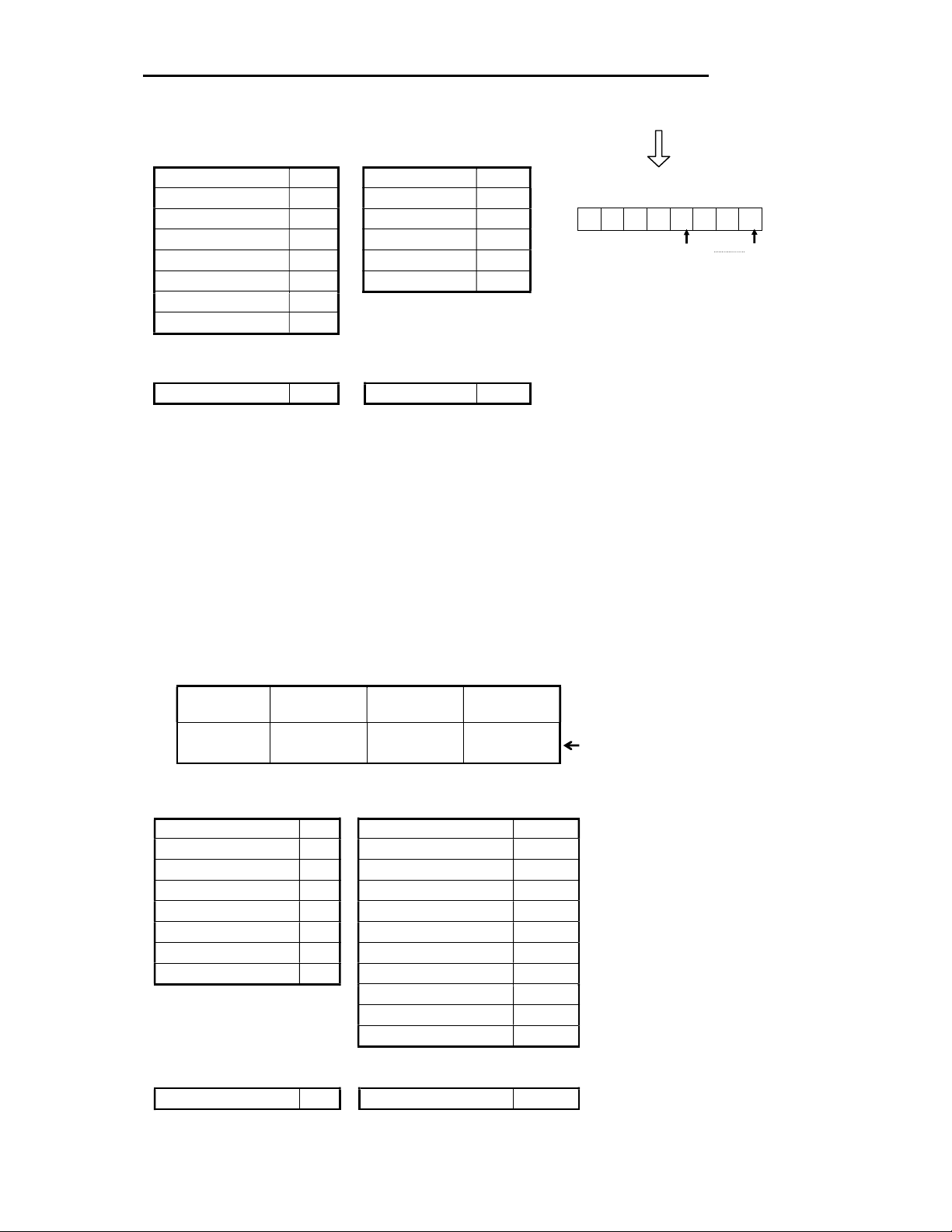
Example) Reading of 4 digital input setting value reference numbers from 10109 to 10112 of the slave 2
Reference
number
Data ON OFF ON OFF - - - -
10109 10110 10111 10112 10113 10114 10115 10116
- 23 -
Page 27
CRC (L)
is responded as the reference
numbers from 10113 to 10116 do not
<RTU mode>
Master→Instrument Instrument→Master (Normal)
Slave address 02H
Function code 02H
Start No. (H) 00H
End No. (L) 6CH
Number of data (H) 00H
Number of data (L) 04H
CRC (H)
<ASCII mode error check>
Error check: The CRC (L) and the CRC (H) parts are as follows.
Note) The start number (Relative number) is “Reference number - 10001”.
Note) The data pieces are the number of bytes of data.
Level 1 Level 2 Level 3 Level 4
CH1 Event activation status
Slave address 02H
Function code 02H
Data pieces 01H
First 8 data 05H
CRC (L) 61H
CRC (H) CFH
B9H
E7H
LRC 8CH
(Decimal 108 (= 10109 - 10001) → Hexadecimal 6CH)
(It differs from the number of data requested. In the example, the requested number of data is 4 and
the data piece is 1.)
LRC F6H
“0” is responded as no
reference number exists.
First 8 data
0 0 0 0 0 1 0 1
10112 10109
Reference number
“0”
exist.
(05H)
5.5.3 Reading of analog setting values (Reading of maintenance register
contents)
[Function code: 03 (03H)]
“Analog setting values (2 bytes: 16 bits) with the continuous numbers” are read for the number of data
specified from the start number specified. The data is arranged by splitting into higher 8 bits and lower 8 bits in
numerical order and configures a data of the response message.
Example) Reading of the range high/low limits and the decimal point of Channel 1 of the slave 2
(Reading of 3 analog setting value reference numbers from 40104 to 40106 of the slave 2)
Reference
number
Data
<RTU mode>
Master→Instrument
Slave address 02H
Function code 03H
Start No. (H) 00H
End No. (L) 67H
Number of data (H) 00H
Number of data (L) 03H High limit value data (H) 03H
CRC (L)
CRC (H) 27H
Decimal point data (L) 01H
CRC (L) 74H
CRC (H) 35H
<ASCII mode error check>
LRC
Note) The start number (Relative number) is “Reference number - 40001”.
(Decimal 103 (= 40104 - 40001) → Hexadecimal 67H)
40104 40105 40106
0
(0000H)
B4H High limit value data (L) E8H
91
1000
(03E8H)
Instrument→Master (Normal)
Slave address 02H
Function code 03H
Data pieces 06H
Low limit value data (H) 00H
Low limit value data (L) 00H
Decimal point data
LRC 09H
(0001H)
1
Data example 0.0 ~ 100.0
00H
- 24 -
Page 28
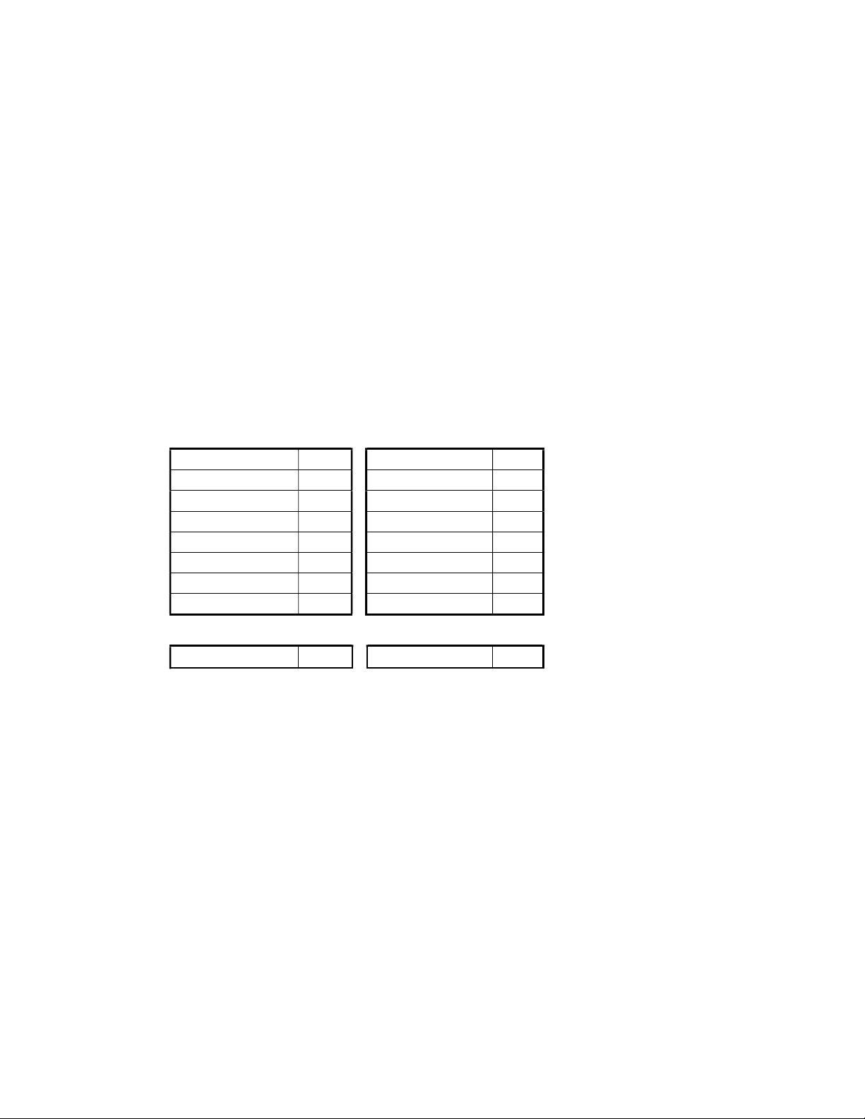
Note) The data pieces are the number of bytes of data.
(It differs from the number of data requested. In the example, the requested number of data is 3 and the
data pieces are 6.)
Note) There is a limitation on the data pieces for the message (that this unit can transmit) that can be
received at a time. (Refer to “5.4 Message creation“)
5.5.4 Reading of analog input data (Reading of input register contents)
[Function code: 04 (034)]
“Analog input data (2 bytes: 16 bits) with the continuous numbers” are read for the number of data specified
from the start number specified. The data is arranged by splitting into higher 8 bits and lower 8 bits in
numerical order and configures a data of the response message. The response example is same as
“Function code 03”, but the start number (Relative number) is “Reference number – 30001”.
5.5.5 Writing of digital setting values (Changing of single coil status)
[Function code: 05 (05H)]
The digital setting value specified is put into the status (ON/OFF) specified.
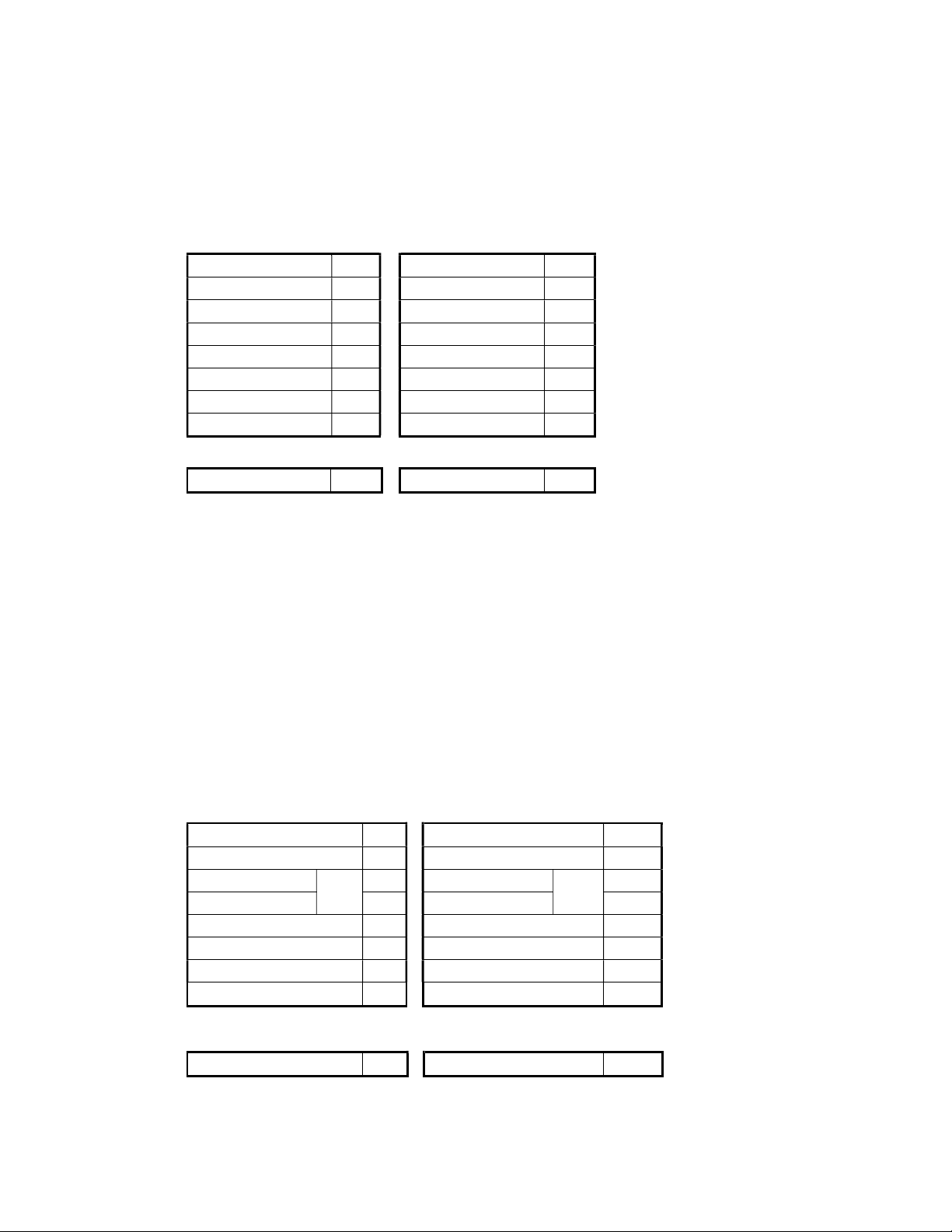
Example) Execution of the marker text writing of the slave 2 (The digital setting value reference number
20 of the slave 2 is turned ON.)
<RTU mode>
Master→Instrument
Slave address 02H
Function code 05H
Setting value No. (H) 00H Setting value No. (H) 00H
Setting value No. (L) 13H
Setting status (H) FFH
Setting status (L) 00H
CRC (L) 7DH
CRC (H) CCH
Instrument→Master (Normal)
Slave address 02H
Function code 05H
Setting value No. (L) 13H
Setting status (H) FFH
Setting status (L) 00H
CRC (L) 7DH
CRC (H) CCH
<ASCII mode error check>
LRC E7H
Note) In case of a normal response, the response is same as a command message.
Note) The setting value number (Relative number) is “Reference number - 1”. (Decimal 19 (= 20 - 1)
→ Hexadecimal 13H)
Note) Set “F00HH” at the execution. In the key lock and the record ON/OFF, set “0000H” to turn OFF
and “FF00H” to turn ON.
Note) When the slave address is set to 0, all slaves perform this command, but no slave responds.
LRC E7H
- 25 -
Page 29
5.5.6 Writing of analog setting values (Writing of single maintenance resister)
[Function code: 06 (06H)]
The analog setting value specified is put into the value specified.
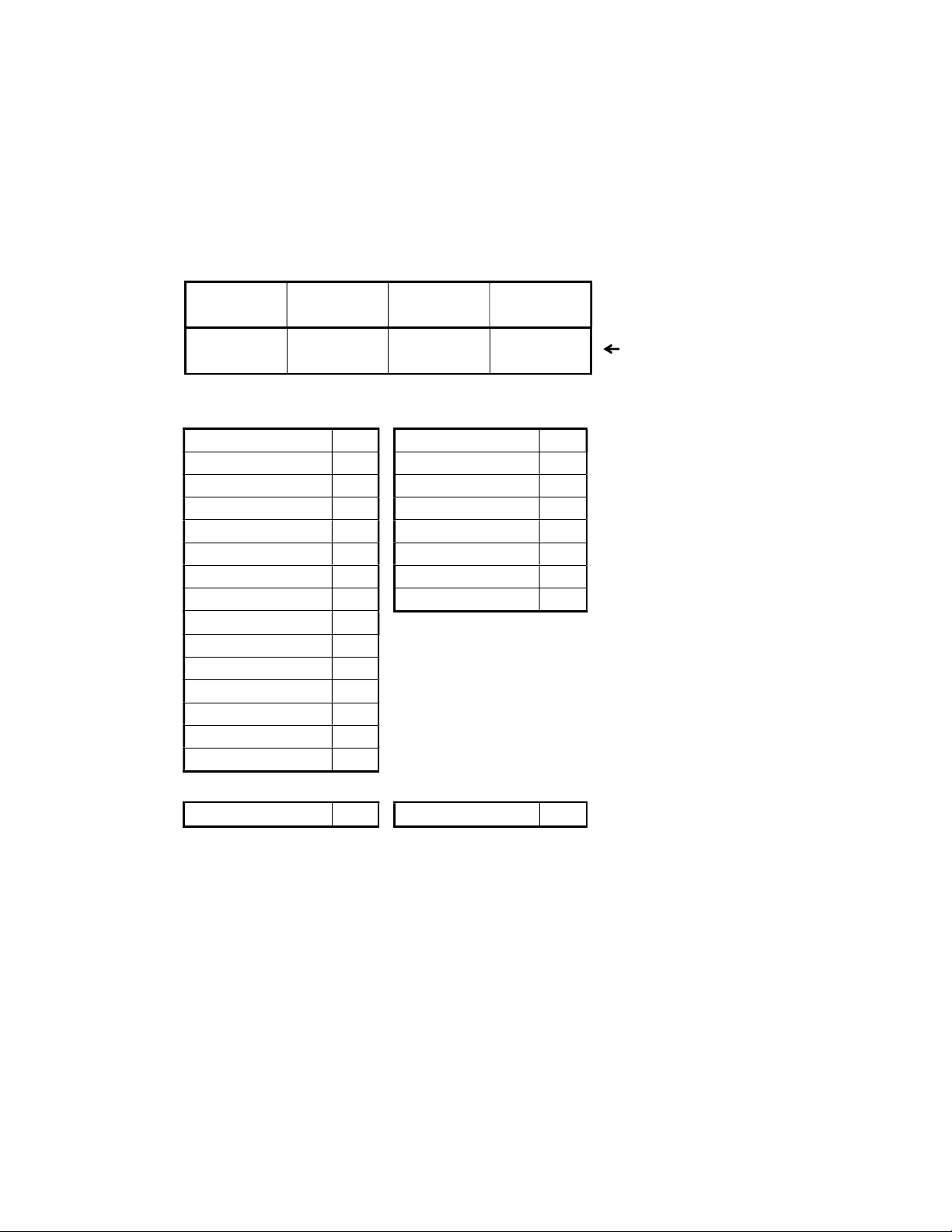
Example) Setting of the sensor correction value of Channel 1 of the slave 2 to 20
(Setting of the analog setting value reference number 40111 of the slave 2 to “20”.)
<RTU mode>
Master→Instrument
Slave address 02H
Function code 06H
Setting value No. (H) 00H
Setting value No. (L) 6EH
Setting data (H) 00H
Setting data (L) 14H
CRC (L) E8H
CRC (H) 2BH
Instrument→Master (Normal)
Slave address 02H
Function code 06H
Setting value No. (H) 00H
Setting value No. (L) 6EH
Setting data (H) 00H
Setting data (L) 14H
CRC (L) E8H
CRC (H) 2BH
<ASCII mode error check>
LRC 76H
Note) In case of a normal response, the response is same as a command message.
Note) The setting value number (Relative number) is “Reference number - 40001”.
(Decimal 110 (= 40111 - 40001) → Hexadecimal 6EH)
Note) When the slave address is set to 0, all slaves perform this command, but no slave responds.
LRC 76H
5.5.7 Loop back test
[Function code: 08 (08H)]
The transmission check is performed between the master and slaves. The response is performed according to
the diagnosis code specified. With this unit, “Return check by transmitting the received data as it is” is performed
and the diagnosis code is fixed with “0000H”.
Example) Execution of "Loop back test" in the slave 2
<RTU mode>
Master→Instrument
Slave address 02H
Function code 08H
Diagnosis code (H)
Diagnosis code (L)
Optional data *
Optional data *
CRC (L) *
CRC (H) *
<ASCII mode error check>
LRC *
Fixed
00H
00H
Instrument→Master (Normal)
Slave address 02H
Function code 08H
Diagnosis code (H)
Diagnosis code (L)
Received data *
Received data *
CRC (L) *
CRC (H) *
LRC
Fixed
00H
00H
*
- 26 -
Page 30
5.5.8 Writing multiple analog setting values (Writing to multiple maintenance
registers)
[Function code: 16 (10H)]
The specified number of the analog setting values from the start number specified is put into the values
specified. The data is arranged and sent by splitting into higher 8 bits and lower 8 bits in numerical order.
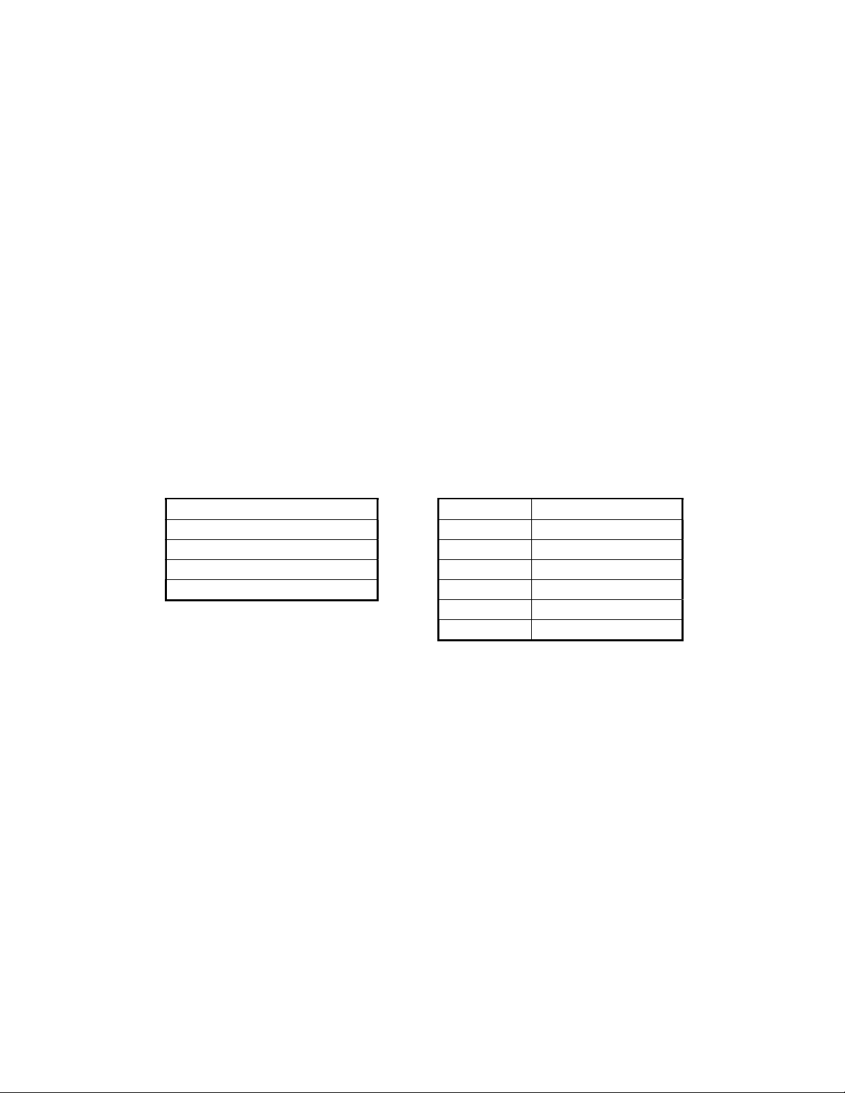
Example) Setting of the range high/low limit values and the decimal point of Channel 1 of the slave 2
to 0.0 ~ 100.0
(Set ting of 3 analog setting value reference numbers from 40104 to 40106 of the slave 2)
Reference
number
Data
<RTU mode>
Master→Instrument
Slave address 02H
Function code 10H
Start No. (H) 00H
End No. (L) 67H
Number of data (H) 00H
Number of data (L) 03H
Data pieces 06H
First dada (H) 00H
First data (L) 00H
Second data (H) 03H
Second data (L) E8H
Third data (H) 00H
Third data (L) 01H
CRC (L) 10H
CRC (H) 97H
<ASCII mode error check>〉
LRC 92H
Note) The start number (Relative number) is “Reference number - 40001”.
(Decimal 103 (= 40104 - 40001) → Hexadecimal 67H)
Note) When the slave address is set to 0, all slaves perform this command, but no slave responds.
Note) There is a limitation on the data pieces for the message (that this unit can receive) that can be
sent at a time. (Refer to “5.4 Message creation”)
40104 40105 40106
0
(0000H)
1000
(03E8H)
Instrument→Master (Normal)
Slave address 02H
Function code 10H
Start No. (H) 00H
End No. (L) 67H
Number of data (H) 00H
Number of data (L) 03H
CRC (L) 31H
CRC (H) E4H
LRC 84H
(0001H)
1
Data example 0.0 ~ 100.0
- 27 -
Page 31
5.6 Process during abnormality
The followings are responses when there is an error in the message content from the master.
5.6.1 No response
In the following cases, the message is ignored and no response is performed.
1) When a transmission error (overrun, framing, parity, CRC, or LRC) is detected in the message
2) When the slave address in the message is not ones own address
3) When the data interval of the message is long
RTU mode... 28 bits hour or more
ASCII mode … 1 second or more
4) When the transmission parameter does not match
5) When the received message exceeds 512 bytes
Note) When the slave address is “0” in the writing function, if there is no error in the message, the message
is performed but no response is performed.
5.6.2 Error message response
When the following error is detected in the message content not having any error shown in Para. 5.6.1 from the
master, the code showing its error content is responded as the “Error message”.
The format of the error message is as follows.
Slave address
Function code + 80H
Error code
CRC (L)
CRC (H)
Function code Function code + 80H
02 82H
03 83H
04 84H
06 86H
08 88H
16 90H
- 28 -
Page 32

The error codes are as follows.
Error code
01H
02H
03H
11H
12H
Content
Defect of a function code
When the function code not defined is received
Defect of a Relative number (Reference number)
When the received starting number or the received setting value number are other than defined
Defect of the number of data
In case of any of the followings
1) When the received function code and the number of data do not match
When “data pieces” is not twice the “number of data” in case of the function code “16”
2) When the number of data to be sent in response to the received message exceeds the
number of data defined
Maximum 120 data (RTU), Maximum 120 data (ASCII)
Out of setting value range (Set error)
In case of any of the followings
1) For the range No., etc. not defined
2) When the setting value (binary) exceeds the range of “-30000 ~ 30000”
3) When the decimal point data exceeds the range of “0 ~ 3”
4) When the RJ is set to “internal” for other than thermocouple input ranges
5) When the burnout is set to “enable” for other than thermocouple input ranges, etc.
Setting impossible
When a setting message is received in any of the following cases
When the parameter setting message for multiple channels at the parameter setting for each
channel
When the parameter setting message for an optional function not built-in
(“0” is responded to a message for reading.)
When the setting is being performed through the instrument and the Web screen
When the setting content is being registered
(The registration starts 3 seconds after the last setting frame is received. The registration
takes about 1 second.)
- 29 -
Page 33
5.7 Reference table
5.7.1 Digital setting values
Reference
number
01
17
20 05 W Marker text writing
Applied function
code
01
05
01
05
R/W
R
W
R
W
Record ON/OFF
R/W … R: READ, W: WRITE
Content Detail
0 (0000h) = Keylock disabled
1 (FF00h) = Keylock enabled
Keylock
The figures shown in parentheses are for the
function code 05.
Error code: 01H, 02H, 03H, 11H, 12H
0 (0000h) = Record OFF
1 (FF00h) = Record ON
The figures shown in parentheses are for the
function code 05.
Error code: 01H, 02H, 03H, 11H, 12H
1 (FF00h) = Marker text writing
Writing of the text with the number specified
by 48002 to the group specified by the
analog setting value reference number
48001
The figures shown in parentheses are for the
function code 05.
Error code: 01H, 02H, 03H, 11H, 12H
- 30 -
Page 34

Applied function
5.7.2 Digital input data
Reference
number
10101
10102
10105
10106
10107
10108
10109
10110
10111
10112
10117
10118
code
02 R CH1 status 1
02 R CH1 status 2
02 R
02 R CH2 status 1
R/W
CH1 alarm 1 activated
CH1 alarm 2 activated
CH1 alarm 3 activated
CH1 alarm 4 activated
Content Detail
Status expression in 2 bits
00: Measured data
01: Calculated data
Error code: 01H, 02H, 03H
Status expression in 4 bits
0000: Normal data
0001: +over range
0010: -over range
0100: Burnout
1000: Invalid data
Error code: 01H, 02H, 03
0: Not activated
1: Alarm activated
Error code: 01H, 02H, 03
Status expression in 2 bits
00: Measured data
01: Calculated data
Error code: 01H, 02H, 03H
10121
10122
10123
10124
10125
10126
10127
10128
10133
10134
10137
10138
10139
10140
10141
10142
10143
10144
10149 ~
10160
10165 ~
10176
10181 ~
10192
02 R CH2 status 2
CH2 alarm 1 activated
02 R
02 R CH3 status 1
02 R CH3 status 2
02 R
02 R
02 R
02 R
CH2 alarm 2 activated
CH2 alarm 3 activated
CH2 alarm 4 activated
CH3 alarm 1 activated
CH3 alarm 2 activated
CH3 alarm 3 activated
CH3 alarm 4 activated
From CH4 event level 1 to CH4 event
level 4 activated
From CH5 event level 1 to CH5 event
level 4 activated
From CH6 event level 1 to CH6 event
level 4 activated
Status expression in 4 bits
0000: Normal data
0001: +over range
0010: -over range
0100: Burnout
1000: Invalid data
Error code: 01H, 02H, 03
0: Not activated
1: Alarm activated
Error code: 01H, 02H, 03
Status expression in 2 bits
00: Measured data
01: Calculated data
Error code: 01H, 02H, 03H
Status expression in 4 bits
0000: Normal data
0001: +over range
0010: -over range
0100: Burnout
1000: Invalid data
Error code: 01H, 02H, 03
0: Not activated
1: Alarm activated
Error code: 01H, 02H, 03
Same as CH1
Same as CH1
Same as CH1
- 31 -
Page 35
Applied function
Reference
number
10197 ~
10208
10213 ~
10224
10229 ~
10240
10245 ~
10256
10261 ~
10272
10277 ~
10288
10293 ~
10304
10309 ~
10320
10325 ~
10336
10341 ~
10352
10357 ~
10368
10373 ~
10384
10389 ~
10400
10405 ~
10416
10421 ~
10432
10437 ~
10448
10453 ~
10464
10469 ~
10480
10485 ~
10496
10501 ~
10512
10517 ~
10528
10533 ~
10544
10549 ~
10560
code
02 R
02 R
02 R
02 R
02 R
02 R
02 R
02 R
02 R
02 R
02 R
02 R
02 R
02 R
02 R
02 R
02 R
02 R
02 R
02 R
02 R
02 R
02 R
R/W
From CH7 event level 1 to CH7 event
level 4 activated
From CH8 event level 1 to CH8 event
level 4 activated
From CH9 event level 1 to CH9 event
level 4 activated
From CH10 event level 1 to CH10 event
level 4 activated
From CH11 event level 1 to CH11 event
level 4 activated
From CH12 event level 1 to CH12 event
level 4 activated
From CH13 event level 1 to CH13 event
level 4 activated
From CH14 event level 1 to CH14 event
level 4 activated
From CH15 event level 1 to CH15 event
level 4 activated
From CH16 event level 1 to CH16 event
level 4 activated
From CH17 event level 1 to CH17 event
level 4 activated
From CH18 event level 1 to CH18 event
level 4 activated
From CH19 event level 1 to CH19 event
level 4 activated
From CH20 event level 1 to CH20 event
level 4 activated
From CH21 event level 1 to CH21 event
level 4 activated
From CH22 event level 1 to CH22 event
level 4 activated
From CH23 event level 1 to CH23 event
level 4 activated
From CH24 event level 1 to CH24 event
level 4 activated
From CH25 event level 1 to CH25 event
level 4 activated
From CH26 event level 1 to CH26 event
level 4 activated
From CH27 event level 1 to CH27 event
level 4 activated
From CH28 event level 1 to CH28 event
level 4 activated
From CH29 event level 1 to CH29 event
level 4 activated
Content Detail
Same as CH1
Same as CH1
Same as CH1
Same as CH1
Same as CH1
Same as CH1
Same as CH1
Same as CH1
Same as CH1
Same as CH1
Same as CH1
Same as CH1
Same as CH1
Same as CH1
Same as CH1
Same as CH1
Same as CH1
Same as CH1
Same as CH1
Same as CH1
Same as CH1
Same as CH1
Same as CH1
- 32 -
Page 36
Applied function
Reference
number
10565 ~
10576
10581 ~
10592
10597 ~
10608
10613 ~
10624
10629 ~
10640
10645 ~
10656
10661 ~
10672
10677 ~
10688
10693 ~
10704
10709 ~
10720
10725 ~
10736
10741 ~
10752
10757 ~
10768
10773 ~
10784
10789 ~
10800
code
02 R
02 R
02 R
02 R
02 R
02 R
02 R
02 R
02 R
02 R
02 R
02 R
02 R
02 R
02 R
R/W
From CH30 event level 1 to CH30 event
level 4 activated
From CH31 event level 1 to CH31 event
level 4 activated
From CH32 event level 1 to CH32 event
level 4 activated
From CH33 event level 1 to CH33 event
level 4 activated
From CH34 event level 1 to CH34 event
level 4 activated
From CH35 event level 1 to CH35 event
level 4 activated
From CH36 event level 1 to CH36 event
level 4 activated
From CH37 event level 1 to CH37 event
level 4 activated
From CH38 event level 1 to CH38 event
level 4 activated
From CH39 event level 1 to CH39 event
level 4 activated
From CH40 event level 1 to CH40 event
level 4 activated
From CH41 event level 1 to CH41 event
level 4 activated
From CH42 event level 1 to CH42 event
level 4 activated
From CH43 event level 1 to CH43 event
level 4 activated
From CH44 event level 1 to CH44 event
level 4 activated
Content Detail
Same as CH1
Same as CH1
Same as CH1
Same as CH1
Same as CH1
Same as CH1
Same as CH1
Same as CH1
Same as CH1
Same as CH1
Same as CH1
Same as CH1
Same as CH1
Same as CH1
Same as CH1
- 33 -
Page 37
Applied function
5.7.3 Analog input data
1) Reading of instrument specifications
R/W … R: READ, W: WRITE
Reference
number
code
30001 04 R Instrument name character 1, 2 ASCII ”KR”
30002 04 R Instrument name character 3, 4 ASCII “21”
30003 04 R Instrument name character 5, 6
30009 04 R ROM version character 1, 2 ASCII 2 digits
30010 04 R ROM version character 3, 4 ASCII 2 digits
30011 04 R ROM version character 5, 6 ASCII 2 digits
30012 04 R ROM version character 7, 8 ASCII 2 digits
30017 04 R Input point 6: 6 points, 12: 12 points
30025 04 R Alarm output point
30026 04 R External contact
30079 04 R Serial number 1, 2 ASCII 2 digits
30080 04 R Serial number 3, 4 ASCII 2 digits
30081 04 R Serial number 5, 6 ASCII 2 digits
30082 04 R Serial number 7, 8 ASCII 2 digits
30083 04 R Serial number 9, 10 ASCII 2 digits
30084 04 R Serial number 11, 12 ASCII 2 digits
30085 04 R Serial number 13, 14 ASCII 2 digits
30086 04 R Serial number 15, 16 ASCII 2 digits
30087 04 R Built date 1, 2 ASCII 2 digits
30088 04 R Built date 3, 4 ASCII 2 digits
30089 04 R Built date 5, 6 ASCII 2 digits
30090 04 R Built date 7, 8 ASCII 2 digits
30091 04 R MAC address 1, 2 MAC address 1, 2
30092 04 R MAC address 3, 4 MAC address 3, 4
30093 04 R MAC address 5, 6 MAC address 5, 6
30094 04 R Communication kind
R/W
Content Detail
ASCII “60”: 6 points, “20”: 12
points
12: 12 points, 8: 8 points, 6: 6
points, 4: 4 points, 0: None
Optional external contact
Enable: 1, Disable: 0
01:High order+Low order(read)
12:High order+Low order(write)
- 34 -
Page 38
Applied function
2) Reading of measured data
Reference
number
30101 04 R CH1 Measured data
30102 04 R CH1 decimal point/status
30103 04 R CH2 measured data Same as CH1
30104 04 R CH2 decimal point/status Same as CH1
30105 04 R CH3 measured data Same as CH1
30106 04 R CH3 decimal point/status Same as CH1
30107 04 R CH4 measured data Same as CH1
30108 04 R CH4 decimal point/status Same as CH1
30109 04 R CH5 measured data Same as CH1
30110 04 R CH5 decimal point/status Same as CH1
30111 04 R CH6 measured data Same as CH1
30112 04 R CH6 decimal point/status Same as CH1
30113 04 R CH7 measured data Same as CH1
30114 04 R CH7 decimal point/status Same as CH1
30115 04 R CH8 measured data Same as CH1
30116 04 R CH8 decimal point/status Same as CH1
30117 04 R CH9 measured data Same as CH1
30118 04 R CH9 decimal point/status Same as CH1
30119 04 R CH10 measured data Same as CH1
30120 04 R CH10 decimal point/status Same as CH1
30121 04 R CH11 measured data Same as CH1
30122 04 R CH11 decimal point/status Same as CH1
30123 04 R CH12 measured data Same as CH1
30124 04 R CH12 decimal point/status Same as CH1
30125 04 R CH13 measured data Same as CH1
30126 04 R CH13 decimal point/status Same as CH1
30127 04 R CH14 measured data Same as CH1
30128 04 R CH14 decimal point/status Same as CH1
30129 04 R CH15 measured data Same as CH1
30130 04 R CH15 decimal point/status Same as CH1
30131 04 R CH16 measured data Same as CH1
30132 04 R CH16 decimal point/status Same as CH1
30133 04 R CH17 measured data Same as CH1
30134 04 R CH17 decimal point/status Same as CH1
30135 04 R CH18 measured data Same as CH1
30136 04 R CH18 decimal point/status Same as CH1
code
R/W
Content Detail
DATA: -30000 ~ 30000
32767: High limit over flow
-32767: Low limit over flow
32765: RJ error
32766: Burnout
-32765: Invalid data
32764: Calculation error
Error code: 01H, 02H, 03H, 12H
(The exponent part is described later.)
Data status, event status, decimal point
(discussed later)
Error code: 01H, 02H, 03H, 12H
R/W … R: READ, W: WRITE
- 35 -
Page 39
Applied function
Reference
number
30137 04 R CH19 measured data Same as CH1
30138 04 R CH19 decimal point/status Same as CH1
30139 04 R CH20 measured data Same as CH1
30140 04 R CH20 decimal point/status Same as CH1
30141 04 R CH21 measured data Same as CH1
30142 04 R
30143 04 R
30144 04 R
30145 04 R
30146 04 R
30147 04 R
30148 04 R
30149 04 R
30150 04 R
30151 04 R
30152 04 R
30153 04 R
30154 04 R
30155 04 R
30156 04 R
30157 04 R
30158 04 R
30159 04 R
30160 04 R
30161 04 R
30162 04 R
30163 04 R
30164 04 R
30165 04 R
30166 04 R
30167 04 R
30168 04 R
30169 04 R
30170 04 R
30171 04 R
30172 04 R
30173 04 R
30174 04 R
30175 04 R
30176 04 R
30177 04 R
30178 04 R
30179 04 R
30180 04 R
30181 04 R
code
R/W
Content Detail
CH21 decimal point/status Same as CH1
CH22 measured data Same as CH1
CH22 decimal point/status Same as CH1
CH23 measured data Same as CH1
CH23 decimal point/status Same as CH1
CH24 measured data Same as CH1
CH24 decimal point/status Same as CH1
CH25 measured data Same as CH1
CH25 decimal point/status Same as CH1
CH26 measured data Same as CH1
CH26 decimal point/status Same as CH1
CH27 measured data Same as CH1
CH27 decimal point/status Same as CH1
CH28 measured data Same as CH1
CH28 decimal point/status Same as CH1
CH29 measured data Same as CH1
CH29 decimal point/status Same as CH1
CH30 measured data Same as CH1
CH30 decimal point/status Same as CH1
CH31 measured data Same as CH1
CH31 decimal point/status Same as CH1
CH32 measured data Same as CH1
CH32 decimal point/status Same as CH1
CH33 measured data Same as CH1
CH33 decimal point/status Same as CH1
CH34 measured data Same as CH1
CH34 decimal point/status Same as CH1
CH35 measured data Same as CH1
CH35 decimal point/status Same as CH1
CH36 measured data Same as CH1
CH36 decimal point/status Same as CH1
CH37 measured data Same as CH1
CH37 decimal point/status Same as CH1
CH38 measured data Same as CH1
CH38 decimal point/status Same as CH1
CH39 measured data Same as CH1
CH39 decimal point/status Same as CH1
CH40 measured data Same as CH1
CH40 decimal point/status Same as CH1
CH41 measured data Same as CH1
- 36 -
Page 40
Applied function
Reference
number
code
30182 04 R
30183 04 R
30184 04 R
30185 04 R
30186 04 R
R/W
Content Detail
CH41 decimal point/status Same as CH1
CH42 measured data Same as CH1
CH42 decimal point/status Same as CH1
CH43 measured data Same as CH1
CH43 decimal point/status Same as CH1
30187 04 R CH44 measured data Same as CH1
30188 04 R CH44 decimal point/status Same as CH1
*About the exponent part form data format.
MSB(15) (14) (4) (3) LSB(0)
Integer
part
sign
Integer part(10 bit)
Exponent
part
sign
Exponent part(4 bit)
Integer part sign :sign 0(+) / 1(-)
Exponent part sign :sign 0(+) / 1(-)
*About the error
1023 :Over High limit over flow
1022 :Under Low limit over flow
1021 :RJ RJ error
1020 :BURN Burnout
1019 :Cal Calculation error
1018 :Other error
1017 :Invalid data
* About the decimal point/status information
MSB(15) (11) (7) (4) (3) LSB(0)
0 0 0 0 SCALE EV4 EV3 EV2 EV1 ERR BURN OF UF DP
SCALE : Display scale type 0(Standard)/1 (Logarithm)
EV1 ~ 4 : Each alarm status 0 (Not activated)/1 (activated)
ERR : Input part status 0 (normal)/1 (abnormal)
BURN : Sensor disconnection 0 (Not activated)/1 (activated)
OF : Overflow error 0 (Not activated)/1 (activated)
UF : Underflow error 0 (Not activated)/1 (activated)
DP : Data decimal place |0|0|0|0|: 0, |0|0|0|1|: 1, |0|0|1|0|: 2
|0|0|1|1|: 3
- 37 -
Page 41

5.7.4 Analog setting values
1) Common parameters (Date/time, upper communications, etc.)
Reference
number
40001
40002
40003
40004
40005
40006
40031
40032
40033
Applied function
code
03
06
16
03
06
16
03
06
16
03
06
16
03
06
16
03
06
16
03
06
16
03
06
16
03
06
16
R/W Content Detail
R
W W Date/time setting 1, 2
R
W W Date/time setting 3, 4
R
W W Date/time setting 5, 6
R
W W Date/time setting 7, 8
R
W W Date/time setting 9, 10
R
W W Date/time setting 11, 12
R
W
W
R
W
W
R
W
W
Upper transmission
mode
Upper l instrument
address
Upper transmission
speed
Year, ASCII 2 digits
00: Year 2000 ~ 99: Year 2099
Error code: 01H, 02H, 03H, 11H, 12H
Month, ASCII 2 digits
Error code: 01H, 02H, 03H, 11H, 12H
Day, ASCII 2 digits
Error code: 01H, 02H, 03H, 11H, 12H
Hour, ASCII 2 digits
Error code: 01H, 02H, 03H, 11H, 12H
Minute, ASCII 2 digits
Error code: 01H, 02H, 03H, 11H, 12H
Second, ASCII 2 digits
Error code: 01H, 02H, 03H, 11H, 12H
0: RTU mode, 1: ASCII mode
Error code: 01H, 02H, 03H, 11H, 12H
1 ~ 31
Error code: 01H, 02H, 03H, 11H, 12H
3: 9600bps, 4: 19200bps
Error code: 01H, 02H, 03H, 11H, 12H
40034
40072
40073
40074
40075
03
06
16
03
06
16
03
06
16
03
06
16
03
06
16
R
W
W
R
W
W
R
W W Frequency selection
R
W
W
R
W W Number of using loop
Upper transmission
character
Decimal point mark
Filter level
0: 8N1, 1: 8N2, 2: 8E1, 3: 8E2, 4: 8O1,
5: 8O2, 6: 7E1, 7: 7E2, 8: 7O1, 9: 7O2
Error code: 01H, 02H, 03H, 11H, 12H
0: Dot, 1: Comma
Error code: 01H, 02H, 03H, 11H, 12H
1: 50Hz, 2: 60Hz
Error code: 01H, 02H, 03H, 11H, 12H
0 ~ 3
Error code: 01H, 02H, 03H, 11H, 12H
1 ~ 5
Error code: 01H, 02H, 03H, 11H, 12H
- 38 -
Page 42
Reference
number
40076
40077
40078
40079
40080
40081
40082
40083
40084
40085
40086
40087
40091
40092
Applied function
code
03
06
16
03
06
16
03
06
16
03
06
16
03
06
16
03
06
16
03
06
16
03
06
16
03
06
16
03
06
16
03
06
16
03
06
16
03
06
16
03
06
16
R/W Content Detail
R
W
W
R
W
W
R
W
W
R
W
W
R
W
W
R
W
W
R
W
W
R
W
W
R
W
W
R
W
W
R
W
W
R
W
W
R
W W Instrument name 1, 2
R
W W Instrument name 3, 4
At writing message,
method of using
remote contact
Overwriting mode
Remote contact
selection
Keylock operation
restriction item
PEN corddinates
Calculation reset/
Automatic reset
ON/OFF
Calculation reset/
at reference
Calculation reset/
for reference
Calculation reset/
at interval
Calculation reset/
for interval
Calculation reset/
Reset by DI
Calculation reset/
Setting method
0: Standard, 1: Binary
Error code: 01H, 02H, 03H, 11H, 12H
0: OFF, 1: ON
Error code: 01H, 02H, 03H, 11H, 12H
0: CF card, 1: USB memory
Error code: 01H, 02H, 03H, 11H, 12H
Bit0:Setting, Bit1:START/STOP key,
Bit2:Display selection ,
Bit3:Group selecton
Bit4:Touch panel operation
Bit5:All keys operation
Error code:01H,02H,03H,11H,12H
0:Smoothness, 1:Directly
Error code:01H,02H,03H,11H,12H
0: OFF, 1: ON
Error code: 01H, 02H, 03H, 11H, 12H
ASCII 2 digits, 00 ~ 23
Error code: 01H, 02H, 03H, 11H, 12H
ASCII 2 digits, 00 ~ 59
Error code: 01H, 02H, 03H, 11H, 12H
ASCII 2 digits, 00 ~ 23
Error code: 01H, 02H, 03H, 11H, 12H
ASCII 2 digits, 00 ~ 59
Error code: 01H, 02H, 03H, 11H, 12H
1 to 8:Channel number, 0:None
Error code: 01H, 02H, 03H, 11H, 12H
0: All CH commonness,1:CH individual
Error code: 01H, 02H, 03H, 11H, 12H
ASCII 2 characters, Shift JIS 1 character
Error code: 01H, 02H, 03H, 11H, 12H
ASCII 2 characters, Shift JIS 1 character
Error code: 01H, 02H, 03H, 11H, 12H
- 39 -
Page 43
Reference
number
40093
40094
40095
40096
40097
40098
Applied function
code
03
06
16
03
06
16
03
06
16
03
06
16
03
06
16
03
06
16
R/W Content Detail
R
W W Instrument name 5, 6
R
W W Instrument name 7, 8
R
W W Instrument name 9, 10
R
W W Instrument name 11, 12
R
W W Instrument name 13, 14
R
W W Instrument name 15, 16
ASCII 2 characters, Shift JIS 1 character
Error code: 01H, 02H, 03H, 11H, 12H
ASCII 2 characters, Shift JIS 1 character
Error code: 01H, 02H, 03H, 11H, 12H
ASCII 2 characters, Shift JIS 1 character
Error code: 01H, 02H, 03H, 11H, 12H
ASCII 2 characters, Shift JIS 1 character
Error code: 01H, 02H, 03H, 11H, 12H
ASCII 2 characters, Shift JIS 1 character
Error code: 01H, 02H, 03H, 11H, 12H
ASCII 2 characters, Shift JIS 1 character
Error code: 01H, 02H, 03H, 11H, 12H
- 40 -
Page 44

Applied function
2) Setting parameters for each channel
(Note) Writing of multiple setting values across channels becomes an error. (Error code 12H)
R/W … R: READ, W: WRITE
Reference
number
40102
40103
40104
40105
40106
40107
40108
40109
40110
40111
40112
40113
code
03
06
16
03
06
16
03
06
16
03
06
16
03
06
16
03
06
16
03
06
16
03
06
16
03
06
16
03
06
16
03
06
16
03
06
16
R/W Content Detail
ASCII code 2 digits (A space code can be
used in the first digit.)
R
W
W
R
W
W
R
W
W
R
W
W
R
W W CH1 range decimal point
R
W
W
R
W
W
R
W W CH1 scale decimal point
R
W
W
R
W W CH1 sensor correction
R
W
W
R
W
W
CH1 range number
CH1 RJ
CH1 range low limit
CH1 range high limit
CH1 scale low limit
CH1 scale high limit
CH1 burnout
CH1 display color
CH1 filter level
CH1 ~ CH12: 01(13.80mV) ~ 80(Pt-Co)
CH13 ~ : 10 (-10.00 ~ 10.00V) fixed
For the optional DI added
CH37 ~ CH42: 90 (DI) ~ 92 (pulse (-))
Error code: 01H, 02H, 03H, 09H, 11H, 12H
0: External, 1: Internal
* For other than thermocouple inputs
“0: External” fixed
Error code: 01H, 02H, 03H, 09H, 11H, 12H
-30000 ~ 30000
Error code: 01H, 02H, 03H, 09H, 11H, 12H
-30000 ~ 30000
Error code: 01H, 02H, 03H, 09H, 11H, 12H
Range decimal place 0 ~ 3
* Same decimal place for range high/low
limits values
Error code: 01H, 02H, 03H, 09H, 11H, 12H
-30000 ~ 30000
Error code: 01H, 02H, 03H, 09H, 11H, 12H
-30000 ~ 30000
Error code: 01H, 02H, 03H, 09H, 11H, 12H
Scale decimal place 0 ~ 3
* Same decimal place for scale high/low
limits values
Error code: 01H, 02H, 03H, 09H, 11H, 12H
0: Disable 1: Up scale, 2: Down scale
Error code: 01H, 02H, 03H, 09H, 11H, 12H
-30000 ~ 30000
* The scale decimal point is used for the
decimal place.
Error code: 01H, 02H, 03H, 09H, 11H, 12H
12 colors 1: Red, 2: Blue, 3: Green, 4:
Brown, 5: Purple, 6: Orange, 7: Gray, 8:
Light blue, 9: Yellow-green, 10: Yellow,
11: Pink, 12: Dark blue
Error code: 01H, 02H, 03H, 09H, 11H, 12H
0:System setting is used
1:[0]none, [1]Weak,[2]Middle,[3]Strong
Error code: 01H, 02H, 03H, 09H, 11H, 12H
- 41 -
Page 45
Applied function
Reference
number
40114
40115
40116
40117
40118
40119
40120
40121
40122
40125
40126
40127
40128
40129
40130
40131
code
03
06
16
03
06
16
03
06
16
03
06
16
03
06
16
03
06
16
03
06
16
03
06
16
03
06
16
03
06
16
03
06
16
03
06
16
03
06
16
03
06
16
03
06
16
03
06
16
R/W Content Detail
R
W W CH1 alarm maker 1,2
R
W W CH1 alarm maker 3,4
R
W
W
R
W
W
R
W
W
R
W
W
R
W
W
R
W
W
R
W
W
R
W
W
R
W
W
R
W
W
R
W
W
R
W
W
R
W
W
R
W
W
CH1 totalizer
Automatic reset
Reset by DI
CH1 totalizer reset
reference hour/minute
CH1 totalizer reset
interval
CH1 unit 1, 2
CH1 unit 3, 4
CH1 unit 5, 6
CH1 unit 7
CH1 tag 1, 2
CH1 tag 3, 4
CH1 tag 5, 6
CH1 tag 7, 8
CH1 tag 9, 10
CH1 tag 11, 12
CH1 tag 13, 14
Higher 1 byte:Alarm marker1 0 to 50
Lower 1 byte:Alarm marker21 0 to 50
Error code: 01H, 02H, 03H, 09H, 11H, 12H
Higher 1 byte:Alarm marker3 0 to 50
Lower 1 byte:Alarm marker4 0 to 50
Error code: 01H, 02H, 03H, 09H, 11H, 12H
Higher 1 byte:totalizer reset[0]OFF,[1]ON
Lower 1 byte:reset by DI 0 to 8([0] is
nine.)
Error code: 01H, 02H, 03H, 09H, 11H, 12H
Higher 1 byte:hour 0 to 23
Lower 1 byte:minute 0 to 59
Error code: 01H, 02H, 03H, 09H, 11H, 12H
Higher 1 byte:hour 0 to 24
Lower 1 byte:minute 0 to 59
Error code: 01H, 02H, 03H, 09H, 11H, 12H
ASCII, Shift JIS 2 digit
Error code: 01H, 02H, 03H, 09H, 11H, 12H
ASCII, Shift JIS 2 digit
Error code: 01H, 02H, 03H, 09H, 11H, 12H
ASCII, Shift JIS 2 digit
Error code: 01H, 02H, 03H, 09H, 11H, 12H
ASCII 1 digit, Low 1 byte - 00H fixed
Error code: 01H, 02H, 03H, 09H, 11H, 12H
ASCII, Shift JIS 2 digit
Error code: 01H, 02H, 03H, 09H, 11H, 12H
ASCII, Shift JIS 2 digit
Error code: 01H, 02H, 03H, 09H, 11H, 12H
ASCII, Shift JIS 2 digit
Error code: 01H, 02H, 03H, 09H, 11H, 12H
ASCII, Shift JIS 2 digit
Error code: 01H, 02H, 03H, 09H, 11H, 12H
ASCII, Shift JIS 2 digit
Error code: 01H, 02H, 03H, 09H, 11H, 12H
ASCII, Shift JIS 2 digit
Error code: 01H, 02H, 03H, 09H, 11H, 12H
ASCII, Shift JIS 2 digit
Error code: 01H, 02H, 03H, 09H, 11H, 12H
- 42 -
Page 46

Applied function
Reference
number
40132
40133
40134
40135
40136
40137
40139
40140
40141
40142
40143
40144
40145
40147
code
03
06
16
03
06
16
03
06
16
03
06
16
03
06
16
03
06
16
03
06
16
03
06
16
03
06
16
03
06
16
03
06
16
03
06
16
03
06
16
03
06
16
R/W Content Detail
R
W
W
R
W
W
R
W
W
R
W
W
R
W
W
R
W W CH1 reference channel 1
R
W
W
R
W
W
R
W
W
R
W
W
R
W
W
R
W
W
R
W W CH1 reference channel 2
R
W
W
CH1 tag 15
CH1 alarm type 1
CH1 setting value 1
CH1 output relay 1
CH1 AND/OR 1
CH1 dead band 1
CH1 alarm delay 1
CH1 alarm type 2
CH1 setting value 2
CH1 output relay 2
CH1 AND/OR 2
CH1 dead band 2
ASCII 1 digit, Low 1 byte - 00H fixed
Error code: 01H, 02H, 03H, 09H, 11H, 12H
0: Disable, 1: High limit, 2: Low limit, 5:
Difference high limit, 6: Difference low
limit, 7: Abnormal data
Error code: 01H, 02H, 03H, 09H, 11H, 12H
-30000 ~ 30000
* The scale decimal point is used for the
decimal place.
Error code: 01H, 02H, 03H, 09H, 11H, 12H
ASCII 2 digits
01 ~ Alarm output point, 00H: No setting
Error code: 01H, 02H, 03H, 09H, 11H, 12H
0: OR, 1: AND
Error code: 01H, 02H, 03H, 09H, 11H, 12H
ASCII 2 digits
Reference channel at difference alarm
No. 01 ~ 44
Error code: 01H, 02H, 03H, 09H, 11H, 12H
0 ~ 30000
* The scale decimal point is used for the
decimal place.
Error code: 01H, 02H, 03H, 09H, 11H, 12H
0 ~ 3600 seconds
Error code: 01H, 02H, 03H, 09H, 11H, 12H
0: Disable, 1: high limit, 2: Low limit, 5:
Difference high limit, 6: Difference low
limit, 7: Abnormal data
Error code: 01H, 02H, 03H, 09H, 11H, 12H
-30000 ~ 30000
* The scale decimal point is used for the
decimal place.
Error code: 01H, 02H, 03H, 09H, 11H, 12H
ASCII 2 digits
01 ~ Alarm output point, 00H: No setting
Error code: 01H, 02H, 03H, 09H, 11H, 12H
0:OR, 1: AND
Error code: 01H, 02H, 03H, 09H, 11H, 12H
ASCII 2 digits
Reference channel at difference alarm
No. 01 ~ 44
Error code: 01H, 02H, 03H, 09H, 11H, 12H
0 ~ 30000
* The scale decimal point is used for the
decimal place.
Error code: 01H, 02H, 03H, 09H, 11H, 12H
- 43 -
Page 47

Applied function
Reference
number
40148
40149
40150
40151
40152
40153
40155
40156
40157
40158
40159
40160
40161
40163
code
03
06
16
03
06
16
03
06
16
03
06
16
03
06
16
03
06
16
03
06
16
03
06
16
03
06
16
03
06
16
03
06
16
03
06
16
03
06
16
03
06
16
R/W Content Detail
R
W
W
R
W
W
R
W
W
R
W
W
R
W
W
R
W W CH1 reference channel 3
R
W
W
R
W
W
R
W
W
R
W
W
R
W
W
R
W
W
R
W W CH1 reference channel 4
R
W
W
CH1 alarm delay 2
CH1 alarm type 3
CH1 setting value 3
CH1 output relay 3
CH1 AND/OR 3
CH1 dead band 3
CH1 alarm delay 3
CH1 alarm type 4
CH1 setting value 4
CH1 output relay 4
CH1 AND/OR 4
CH1 dead band 4
0 ~ 3600 seconds
Error code: 01H, 02H, 03H, 09H, 11H, 12H
0: Disable, 1: high limit, 2: Low limit, 5:
Difference high limit, 6: Difference low
limit, 7: Abnormal data
Error code: 01H, 02H, 03H, 09H, 11H, 12H
-30000 ~ 30000
* The scale decimal point is used for the
decimal place.
Error code: 01H, 02H, 03H, 09H, 11H, 12H
ASCII 2 digits
01 ~ Alarm output point, 00H: No setting
Error code: 01H, 02H, 03H, 09H, 11H, 12H
0:OR, 1: AND
Error code: 01H, 02H, 03H, 09H, 11H, 12H
ASCII2 桁
Reference channel at difference alarm
No. 01 ~ 44
Error code: 01H, 02H, 03H, 09H, 11H, 12H
0 ~ 30000
* The scale decimal point is used for the
decimal place.
Error code: 01H, 02H, 03H, 09H, 11H, 12H
0 ~ 3600 seconds
Error code: 01H, 02H, 03H, 09H, 11H, 12H
0: Disable, 1: high limit, 2: Low limit, 5:
Difference high limit, 6: Difference low
limit, 7: Abnormal data
Error code: 01H, 02H, 03H, 09H, 11H, 12H
-30000 ~ 30000
* The scale decimal point is used for the
decimal place.
Error code: 01H, 02H, 03H, 09H, 11H, 12H
ASCII 2 digits
01 ~ Alarm output point, 00H: No setting
Error code: 01H, 02H, 03H, 09H, 11H, 12H
0:OR, 1: AND
Error code: 01H, 02H, 03H, 09H, 11H, 12H
ASCII 2 digits
Reference channel at difference alarm
No. 01 ~ 44
Error code: 01H, 02H, 03H, 09H, 11H, 12H
0 ~ 30000
* The scale decimal point is used for the
decimal place.
Error code: 01H, 02H, 03H, 09H, 11H, 12H
- 44 -
Page 48
Applied function
Reference
number
40164
40166
40167
40168
40169
40171
40176
40177
40178
40179
40180
40181
40182
40183
40184
code
03
06
16
03
06
16
03
06
16
03
06
16
03
06
16
03
06
16
03
06
16
03
06
16
03
06
16
03
06
16
03
06
16
03
06
16
03
06
16
03
06
16
03
06
16
R/W Content Detail
R
W
W
R
W W CH1 display scale low limit
R
W W CH1 display scale high limit
R
W
W
R
W W CH1 display scale type
R
W
W
R
W
W
R
W W CH1 calculation formula 1, 2
R
W
W
R
W
W
R
W
W
R
W
W
R
W
W
R
W
W
R
W
W
CH1 alarm delay 4
CH1 display scale
decimal point
CH1 range position
(Area belonged)
Calculation ON/OFF
CH1 calculation formula 3, 4
CH1 calculation formula 5, 6
CH1 calculation formula 7, 8
CH1 calculation formula 9, 10
CH1 calculation formula 11, 12
CH1 calculation formula 13, 14
CH1 calculation formula 15, 16
0 ~ 3600 seconds
Error code: 01H, 02H, 03H, 09H, 11H, 12H
-30000 ~ 30000
Error code: 01H, 02H, 03H, 09H, 11H, 12H
-30000 ~ 30000
Error code: 01H, 02H, 03H, 09H, 11H, 12H
0 ~ 3
Error code: 01H, 02H, 03H, 09H, 11H, 12H
0: Standard, 1: Logarithm
Error code: 01H, 02H, 03H, 09H, 11H, 12H
0 ~ 3, At parallel scale 0 ~ 7 (0 ~ 3: First
zone, 4 ~ 7: Second zone)
Error code: 01H, 02H, 03H, 09H, 11H, 12H
0: Not used, 1: Used
Error code: 01H, 02H, 03H, 09H, 11H, 12H
ASCII 2 digits
Error code: 01H, 02H, 03H, 09H, 11H, 12H
ASCII 2 digits
Error code: 01H, 02H, 03H, 09H, 11H, 12H
ASCII 2 digits
Error code: 01H, 02H, 03H, 09H, 11H, 12H
ASCII 2 digits
Error code: 01H, 02H, 03H, 09H, 11H, 12H
ASCII 2 digits
Error code: 01H, 02H, 03H, 09H, 11H, 12H
ASCII 2 digits
Error code: 01H, 02H, 03H, 09H, 11H, 12H
ASCII 2 digits
Error code: 01H, 02H, 03H, 09H, 11H, 12H
ASCII 2 digits
Error code: 01H, 02H, 03H, 09H, 11H, 12H
- 45 -
Page 49
Applied function
Reference
number
40185
40186
40187
40188
40189
40190
40191
40192
code
03
06
16
03
06
16
03
06
16
03
06
16
03
06
16
03
06
16
03
06
16
03
06
16
R/W Content Detail
R
CH1 calculation formula 17, 18
W
W
R
CH1 calculation formula 19, 20
W
W
R
CH1 calculation formula 21, 22
W
W
R
CH1 calculation formula 23, 24
W
W
R
CH1 calculation formula 25, 26
W
W
R
CH1 calculation formula 27, 28
W
W
R
CH1 calculation formula 29, 30
W
W
R
W W CH1 calculation formula 31, 32
ASCII 2 digits
Error code: 01H, 02H, 03H, 09H, 11H, 12H
ASCII 2 digits
Error code: 01H, 02H, 03H, 09H, 11H, 12H
ASCII 2 digits
Error code: 01H, 02H, 03H, 09H, 11H, 12H
ASCII 2 digits
Error code: 01H, 02H, 03H, 09H, 11H, 12H
ASCII 2 digits
Error code: 01H, 02H, 03H, 09H, 11H, 12H
ASCII 2 digits
Error code: 01H, 02H, 03H, 09H, 11H, 12H
ASCII 2 digits
Error code: 01H, 02H, 03H, 09H, 11H, 12H
ASCII 2 digits
Error code: 01H, 02H, 03H, 09H, 11H, 12H
40193
40194
40195
40196
40197
40198
40199
03
06
16
03
06
16
03
06
16
03
06
16
03
06
16
03
06
16
03
06
16
R
W W CH1 calculation formula 33, 34
R
W W CH1 calculation formula 35, 36
R
W W CH1 calculation formula 37, 38
R
W W CH1 calculation formula 39, 40
R
W W CH1 calculation formula 41, 42
R
W W CH1 calculation formula 43, 44
R
W W CH1 calculation formula 45, 46
ASCII 2 digits
Error code: 01H, 02H, 03H, 09H, 11H, 12H
ASCII 2 digits
Error code: 01H, 02H, 03H, 09H, 11H, 12H
ASCII 2 digits
Error code: 01H, 02H, 03H, 09H, 11H, 12H
ASCII 2 digits
Error code: 01H, 02H, 03H, 09H, 11H, 12H
ASCII 2 digits
Error code: 01H, 02H, 03H, 09H, 11H, 12H
ASCII 2 digits
Error code: 01H, 02H, 03H, 09H, 11H, 12H
ASCII 2 digits
Error code: 01H, 02H, 03H, 09H, 11H, 12H
- 46 -
Page 50

Applied function
Reference
number
40200
40202
~
40300
40302
~
40400
40402
~
40500
40502
~
40600
40602
~
40700
40702
~
40800
40802
~
40900
40902
~
41000
41002
~
41100
41102
~
41200
41202
~
41300
41302
~
41400
41402
~
41500
code
03
06
16
03
06
16
03
06
16
03
06
16
03
06
16
03
06
16
03
06
16
03
06
16
03
06
16
03
06
16
03
06
16
03
06
16
03
06
16
03
06
16
R/W Content Detail
R
W W CH1 calculation formula 47, 48
R
W W CH2 setting parameter Same as CH1 parameter (40102 ~ 40200)
R
W W CH3 setting parameter Same as CH1 parameter (40102 ~ 40200)
R
W W CH4 setting parameter Same as CH1 parameter (40102 ~ 40200)
R
W W CH5 setting parameter Same as CH1 parameter (40102 ~ 40200)
R
W W CH6 setting parameter Same as CH1 parameter (40102 ~ 40200)
R
W W CH7 setting parameter Same as CH1 parameter (40102 ~ 40200)
R
W W CH8 setting parameter Same as CH1 parameter (40102 ~ 40200)
R
W W CH9 setting parameter Same as CH1 parameter (40102 ~ 40200)
R
W W CH10 setting parameter Same as CH1 parameter (40102 ~ 40200)
R
W W CH11 setting parameter Same as CH1 parameter (40102 ~ 40200)
R
W W CH12 setting parameter Same as CH1 parameter (40102 ~ 40200)
R
W W CH13 setting parameter Same as CH1 parameter (40102 ~ 40200)
R
W W CH14 setting parameter
ASCII 2 digits
Error code: 01H, 02H, 03H, 09H, 11H, 12H
Same as CH1 parameter (40102 ~ 40200)
41502
~
41600
03
06
16
R
W W CH15 setting parameter
- 47 -
Same as CH1 parameter (40102 ~ 40200)
Page 51

Applied function
Reference
number
41602
~
41700
41702
~
41800
41802
~
41900
41902
~
42000
42002
~
42100
42102
~
42200
42202
~
42300
code
03
06
16
03
06
16
03
06
16
03
06
16
03
06
16
03
06
16
03
06
16
R/W Content Detail
R
W W CH16 setting parameter
R
W W CH17 setting parameter
R
W W CH18 setting parameter
R
W W CH19 setting parameter
R
W W CH20 setting parameter
R
W W CH21 setting parameter
R
W W CH22 setting parameter
Same as CH1 parameter (40102 ~ 40200)
Same as CH1 parameter (40102 ~ 40200)
Same as CH1 parameter (40102 ~ 40200)
Same as CH1 parameter (40102 ~ 40200)
Same as CH1 parameter (40102 ~ 40200)
Same as CH1 parameter (40102 ~ 40200)
Same as CH1 parameter (40102 ~ 40200)
42302
~
42400
42402
~
42500
42502
~
42600
42602
~
42700
42702
~
42800
42802
~
42900
42902
~
43000
43002
~
43100
03
06
16
03
06
16
03
06
16
03
06
16
03
06
16
03
06
16
03
06
16
03
06
16
R
W W CH23 setting parameter
R
W W CH24 setting parameter
R
W W CH25 setting parameter
R
W W CH26 setting parameter
R
W W CH27 setting parameter
R
W W CH28 setting parameter
R
W W CH29 setting parameter
R
W W CH30 setting parameter
Same as CH1 parameter (40102 ~ 40200)
Same as CH1 parameter (40102 ~ 40200)
Same as CH1 parameter (40102 ~ 40200)
Same as CH1 parameter (40102 ~ 40200)
Same as CH1 parameter (40102 ~ 40200)
Same as CH1 parameter (40102 ~ 40200)
Same as CH1 parameter (40102 ~ 40200)
Same as CH1 parameter (40102 ~ 40200)
- 48 -
Page 52
Applied function
Reference
number
43102
~
43200
43202
~
43300
43302
~
43400
43402
~
43500
43502
~
43600
43602
~
43700
43702
~
43800
43802
~
43900
43902
~
44000
44002
~
44100
44102
~
44200
44202
~
44300
44302
~
44400
44402
~
44500
code
03
06
16
03
06
16
03
06
16
03
06
16
03
06
16
03
06
16
03
06
16
03
06
16
03
06
16
03
06
16
03
06
16
03
06
16
03
06
16
03
06
16
R/W Content Detail
R
W W CH31 setting parameter
R
W W CH32 setting parameter
R
W W CH33 setting parameter
R
W W CH34 setting parameter
R
W W CH35 setting parameter
R
W W CH36 setting parameter
R
W W CH37 setting parameter
R
W W CH38 setting parameter
R
W W CH39 setting parameter
R
W W CH40 setting parameter
R
W W CH41 setting parameter
R
W W CH42 setting parameter
R
W W CH43 setting parameter
R
W W CH44 setting parameter
Same as CH1 parameter (40102 ~ 40200)
Same as CH1 parameter (40102 ~ 40200)
Same as CH1 parameter (40102 ~ 40200)
Same as CH1 parameter (40102 ~ 40200)
Same as CH1 parameter (40102 ~ 40200)
Same as CH1 parameter (40102 ~ 40200)
Same as CH1 parameter (40102 ~ 40200)
Same as CH1 parameter (40102 ~ 40200)
Same as CH1 parameter (40102 ~ 40200)
Same as CH1 parameter (40102 ~ 40200)
Same as CH1 parameter (40102 ~ 40200)
Same as CH1 parameter (40102 ~ 40200)
Same as CH1 parameter (40102 ~ 40200)
Same as CH1 parameter (40102 ~ 40200)
- 49 -
Page 53
3) Communications parameter
Reference
number
45001
45002
45003
45004
45005
45006
45010
45011
45012
45013
45014
45015
45016
45017
45018
Applied function
code
03
06
16
03
06
16
03
06
16
03
06
16
03
06
16
03
06
16
03
06
16
03
06
16
03
06
16
03
06
16
03
06
16
03
06
16
03
06
16
03
06
16
03
06
16
R/W Content Detail
R
W
W
R
W
W
R
W
W
R
W
W
R
W W Default gateway 1, 2
R
W W Default gateway 3, 4
R
W
W
R
W
W
R
W
W
R
W
W
R
W
W
R
W
W
R
W
W
R
W
W
R
W
W
IP address 1, 2
IP address 3, 4
Subnet mask1, 2
Subnet mask 3, 4
FTP client directory
1,2
FTP client directory
3,4
FTP client directory
5,6
FTP client directory
7,8
FTP client directory
9,108,9
FTP client directory
11,12
FTP client directory
13,14
FTP client directory
15,16
FTP client directory
17,18
IP address
Error code: 01H, 02H, 03H, 09H, 11H, 12H
IP address
Error code: 01H, 02H, 03H, 09H, 11H, 12H
Subnet mask
Error code: 01H, 02H, 03H, 09H, 11H, 12H
Subnet mask
Error code: 01H, 02H, 03H, 09H, 11H, 12H
Default gateway
Error code: 01H, 02H, 03H, 09H, 11H, 12H
Default gateway
Error code: 01H, 02H, 03H, 09H, 11H, 12H
ASCII 2 digits
Error code: 01H, 02H, 03H, 09H, 11H, 12H
ASCII 2 digits
Error code: 01H, 02H, 03H, 09H, 11H, 12H
ASCII 2 digits
Error code: 01H, 02H, 03H, 09H, 11H, 12H
ASCII 2 digits
Error code: 01H, 02H, 03H, 09H, 11H, 12H
ASCII 2 digits
Error code: 01H, 02H, 03H, 09H, 11H, 12H
ASCII 2 digits
Error code: 01H, 02H, 03H, 09H, 11H, 12H
ASCII 2 digits
Error code: 01H, 02H, 03H, 09H, 11H, 12H
ASCII 2 digits
Error code: 01H, 02H, 03H, 09H, 11H, 12H
ASCII 2 digits
Error code: 01H, 02H, 03H, 09H, 11H, 12H
- 50 -
Page 54
Reference
number
45019
45020
45021
45022
45023
45024
45025
45026
45027
45028
45029
45030
45031
45032
45033
45034
Applied function
code
03
06
16
03
06
16
03
06
16
03
06
16
03
06
16
03
06
16
03
06
16
03
06
16
03
06
16
03
06
16
03
06
16
03
06
16
03
06
16
03
06
16
03
06
16
03
06
16
R/W Content Detail
R
W
W
R
W
W
R
W
W
R
W
W
R
W
W
R
W
W
R
W
W
R
W
W
R
W
W
R
W
W
R
W
W
R
W
W
R
W
W
R
W
W
R
W
W
R
W
W
FTP client directory
19,20
FTP client directory
21,22
FTP client directory
23,24
FTP client directory
25,26
FTP client directory
27,28
FTP client directory
29,30
FTP client directory
31,32
FTP Login user
Name(client/sever)
1,2
FTP Login user
Name(client/sever)
3,4
FTP Login user
Name(client/sever)
5,6
FTP Login user
Name(client/sever)
7,8
FTP Login user
Name(client/sever)
9,10
FTP Login user
Name(client/sever)
11,12
FTP Login user
Name(client/sever)
13,14
FTP Login user
Name(client/sever)
15,16
FTP Login user
Name(client/sever)
17,18
ASCII 2 digits
Error code: 01H, 02H, 03H, 09H, 11H, 12H
ASCII 2 digits
Error code: 01H, 02H, 03H, 09H, 11H, 12H
ASCII 2 digits
Error code: 01H, 02H, 03H, 09H, 11H, 12H
ASCII 2 digits
Error code: 01H, 02H, 03H, 09H, 11H, 12H
ASCII 2 digits
Error code: 01H, 02H, 03H, 09H, 11H, 12H
ASCII 2 digits
Error code: 01H, 02H, 03H, 09H, 11H, 12H
ASCII 2 digits
Error code: 01H, 02H, 03H, 09H, 11H, 12H
ASCII 2 digits
Error code: 01H, 02H, 03H, 09H, 11H, 12H
ASCII 2 digits
Error code: 01H, 02H, 03H, 09H, 11H, 12H
ASCII 2 digits
Error code: 01H, 02H, 03H, 09H, 11H, 12H
ASCII 2 digits
Error code: 01H, 02H, 03H, 09H, 11H, 12H
ASCII 2 digits
Error code: 01H, 02H, 03H, 09H, 11H, 12H
ASCII 2 digits
Error code: 01H, 02H, 03H, 09H, 11H, 12H
ASCII 2 digits
Error code: 01H, 02H, 03H, 09H, 11H, 12H
ASCII 2 digits
Error code: 01H, 02H, 03H, 09H, 11H, 12H
ASCII 2 digits
Error code: 01H, 02H, 03H, 09H, 11H, 12H
- 51 -
Page 55
Reference
number
45035
45036
45037
45038
45039
45040
45041
45042
45043
45044
45045
45046
45047
45048
45049
45050
Applied function
code
03
06
16
03
06
16
03
06
16
03
06
16
03
06
16
03
06
16
03
06
16
03
06
16
03
06
16
03
06
16
03
06
16
03
06
16
03
06
16
03
06
16
03
06
16
03
06
16
R/W Content Detail
R
W
W
R
W
W
R
W
W
R
W
W
R
W
W
R
W
W
R
W
W
R
W
W
R
W
W
R
W
W
R
W
W
R
W
W
R
W
W
R
W
W
R
W
W
R
W
W
FTP Login user
Name(client/sever)
19.20
FTP Login user
Name(client/sever)
21,22
FTP Login user
Name(client/sever)
23,24
FTP Login user
Name(client/sever)
25,26
FTP Login user
Name(client/sever)
27,28
FTP Login user
Name(client/sever)
29,30
FTP Login user
Name(client/sever)
31,32
FTP Login password
(client/sever)
1,2
FTP Login password
(client/sever)
3,4
FTP Login password
(client/sever)
5,6
FTP Login password
(client/sever)
7,8
FTP Login password
(client/sever)
9,10
FTP Login password
(client/sever)
11,12
FTP Login password
(client/sever)
13,14
FTP Login password
(client/sever)
15,16
FTP Login password
(client/sever)
17,18
ASCII 2 digits
Error code: 01H, 02H, 03H, 09H, 11H, 12H
ASCII 2 digits
Error code: 01H, 02H, 03H, 09H, 11H, 12H
ASCII 2 digits
Error code: 01H, 02H, 03H, 09H, 11H, 12H
ASCII 2 digits
Error code: 01H, 02H, 03H, 09H, 11H, 12H
ASCII 2 digits
Error code: 01H, 02H, 03H, 09H, 11H, 12H
ASCII 2 digits
Error code: 01H, 02H, 03H, 09H, 11H, 12H
ASCII 2 digits
Error code: 01H, 02H, 03H, 09H, 11H, 12H
ASCII 2 digits
Error code: 01H, 02H, 03H, 09H, 11H, 12H
ASCII 2 digits
Error code: 01H, 02H, 03H, 09H, 11H, 12H
ASCII 2 digits
Error code: 01H, 02H, 03H, 09H, 11H, 12H
ASCII 2 digits
Error code: 01H, 02H, 03H, 09H, 11H, 12H
ASCII 2 digits
Error code: 01H, 02H, 03H, 09H, 11H, 12H
ASCII 2 digits
Error code: 01H, 02H, 03H, 09H, 11H, 12H
ASCII 2 digits
Error code: 01H, 02H, 03H, 09H, 11H, 12H
ASCII 2 digits
Error code: 01H, 02H, 03H, 09H, 11H, 12H
ASCII 2 digits
Error code: 01H, 02H, 03H, 09H, 11H, 12H
- 52 -
Page 56
Reference
number
45051
45052
45053
45054
45055
45056
45057
45058
45059
45060
45070
45071
45072
45073
45074
45075
Applied function
code
03
06
16
03
06
16
03
06
16
03
06
16
03
06
16
03
06
16
03
06
16
03
06
16
03
06
16
03
06
16
03
06
16
03
06
16
03
06
16
03
06
16
03
06
16
03
06
16
R/W Content Detail
R
FTP Login password
W
W
R
W
W
R
W
W
R
W
W
R
W
W
R
W
W
R
W
W
R
W
W
R
W
W
R
W
W
R
W
W
R
W
W
R
W
W
R
W
W
R
W
W
R
W
W
(client/sever)
FTP Login password
(client/sever)
FTP Login password
(client/sever)
FTP Login password
(client/sever)
FTP Login password
(client/sever)
FTP Login password
(client/sever)
FTP Login password
(client/sever)
FTP client
PASV mode
FTP client
Auto transfer
FTP client
Retry mode
FTP server
FTP server address
FTP server address
FTP server address
FTP server address
FTP server address
19,20
21,22
23,24
25,26
27,28
29,30
31,32
ON/OFF
1, 2
3, 4
5, 6
7, 8
9, 10
ASCII 2 digits
Error code: 01H, 02H, 03H, 09H, 11H, 12H
ASCII 2 digits
Error code: 01H, 02H, 03H, 09H, 11H, 12H
ASCII 2 digits
Error code: 01H, 02H, 03H, 09H, 11H, 12H
ASCII 2 digits
Error code: 01H, 02H, 03H, 09H, 11H, 12H
ASCII 2 digits
Error code: 01H, 02H, 03H, 09H, 11H, 12H
ASCII 2 digits
Error code: 01H, 02H, 03H, 09H, 11H, 12H
ASCII 2 digits
Error code: 01H, 02H, 03H, 09H, 11H, 12H
0:OFF,1:ON
Error code: 01H, 02H, 03H, 09H, 11H, 12H
0:OFF,1:ON
Error code: 01H, 02H, 03H, 09H, 11H, 12H
0:OFF,1:ON
Error code: 01H, 02H, 03H, 09H, 11H, 12H
0: OFF, 1: ON
Error code: 01H, 02H, 03H, 09H, 11H, 12H
ASCII 2 digits
Error code: 01H, 02H, 03H, 09H, 11H, 12H
ASCII 2 digits
Error code: 01H, 02H, 03H, 09H, 11H, 12H
ASCII 2 digits
Error code: 01H, 02H, 03H, 09H, 11H, 12H
ASCII 2 digits
Error code: 01H, 02H, 03H, 09H, 11H, 12H
ASCII 2 digits
Error code: 01H, 02H, 03H, 09H, 11H, 12H
- 53 -
Page 57
Reference
number
45076
45077
45078
45079
45080
45081
45082
45083
45084
45085
45086
45091
45092
45093
45094
45095
Applied function
code
03
06
16
03
06
16
03
06
16
03
06
16
03
06
16
03
06
16
03
06
16
03
06
16
03
06
16
03
06
16
03
06
16
03
06
16
03
06
16
03
06
16
03
06
16
03
06
16
R/W Content Detail
R
FTP server address
W
W
R
FTP server address
W
W
R
W
W
R
W
W
R
W
W
R
W
W
R
W
W
R
W
W
R
W
W
R
W
W
R
W
W
R
Login user name (for
W
W
R
Login user name (for
W
W
R
Login user name (for
W
W
R
Login user name (for
W
W
R
Login user name (for
W
W
13, 14
FTP server address
15, 16
FTP server address
17, 18
FTP server address
19, 20
FTP server address
21, 22
FTP server address
23, 24
FTP server address
25, 26
FTP server address
27, 28
FTP server address
29, 30
FTP server address
31, 32
server) 1, 2
server) 3, 4
server) 5, 6
server) 7, 8
server) 9, 10
11, 12
ASCII 2 digits
Error code: 01H, 02H, 03H, 09H, 11H, 12H
ASCII 2 digits
Error code: 01H, 02H, 03H, 09H, 11H, 12H
ASCII 2 digits
Error code: 01H, 02H, 03H, 09H, 11H, 12H
ASCII 2 digits
Error code: 01H, 02H, 03H, 09H, 11H, 12H
ASCII 2 digits
Error code: 01H, 02H, 03H, 09H, 11H, 12H
ASCII 2 digits
Error code: 01H, 02H, 03H, 09H, 11H, 12H
ASCII 2 digits
Error code: 01H, 02H, 03H, 09H, 11H, 12H
ASCII 2 digits
Error code: 01H, 02H, 03H, 09H, 11H, 12H
ASCII 2 digits
Error code: 01H, 02H, 03H, 09H, 11H, 12H
ASCII 2 digits
Error code: 01H, 02H, 03H, 09H, 11H, 12H
ASCII 2 digits
Error code: 01H, 02H, 03H, 09H, 11H, 12H
ASCII 2 digits
Error code: 01H, 02H, 03H, 09H, 11H, 12H
ASCII 2 digits
Error code: 01H, 02H, 03H, 09H, 11H, 12H
ASCII 2 digits
Error code: 01H, 02H, 03H, 09H, 11H, 12H
ASCII 2 digits
Error code: 01H, 02H, 03H, 09H, 11H, 12H
ASCII 2 digits
Error code: 01H, 02H, 03H, 09H, 11H, 12H
- 54 -
Page 58
Reference
number
45096
45097
45098
45099
45100
45101
45102
45103
45104
45105
45106
45111
45112
45113
45114
45115
Applied function
code
03
06
16
03
06
16
03
06
16
03
06
16
03
06
16
03
06
16
03
06
16
03
06
16
03
06
16
03
06
16
03
06
16
03
06
16
03
06
16
03
06
16
03
06
16
03
06
16
R/W Content Detail
R
Login user name (for
W
W
R
W
W
R
W
W
R
W
W
R
W
W
R
W
W
R
W
W
R
W
W
R
W
W
R
W
W
R
W
W
R
W
W
R
W
W
R
W
W
R
W
W
R
W
W
server) 11, 12
Login user name (for
server) 13, 14
Login user name (for
server) 15, 16
Login user name (for
server) 17, 18
Login user name (for
server) 19, 20
Login user name (for
server) 21, 22
Login user name (for
server) 23, 24
Login user name (for
server) 25, 26
Login user name (for
server) 27, 28
Login user name (for
server) 29,30
Login user name (for
server) 31, 32
Login password (for
server) 1, 2
Login password (for
server) 3, 4
Login password (for
server) 5, 6
Login password (for
server) 7, 8
Login password (for
server) 9, 10
ASCII 2 digits
Error code: 01H, 02H, 03H, 09H, 11H, 12H
ASCII 2 digits
Error code: 01H, 02H, 03H, 09H, 11H, 12H
ASCII 2 digits
Error code: 01H, 02H, 03H, 09H, 11H, 12H
ASCII 2 digits
Error code: 01H, 02H, 03H, 09H, 11H, 12H
ASCII 2 digits
Error code: 01H, 02H, 03H, 09H, 11H, 12H
ASCII 2 digits
Error code: 01H, 02H, 03H, 09H, 11H, 12H
ASCII 2 digits
Error code: 01H, 02H, 03H, 09H, 11H, 12H
ASCII 2 digits
Error code: 01H, 02H, 03H, 09H, 11H, 12H
ASCII 2 digits
Error code: 01H, 02H, 03H, 09H, 11H, 12H
ASCII 2 digits
Error code: 01H, 02H, 03H, 09H, 11H, 12H
ASCII 2 digits
Error code: 01H, 02H, 03H, 09H, 11H, 12H
ASCII 2 digits
Error code: 01H, 02H, 03H, 09H, 11H, 12H
ASCII 2 digits
Error code: 01H, 02H, 03H, 09H, 11H, 12H
ASCII 2 digits
Error code: 01H, 02H, 03H, 09H, 11H, 12H
ASCII 2 digits
Error code: 01H, 02H, 03H, 09H, 11H, 12H
ASCII 2 digits
Error code: 01H, 02H, 03H, 09H, 11H, 12H
- 55 -
Page 59
Reference
number
45116
45117
45118
45119
45120
45121
45122
45123
45124
45125
45126
45141
45142
45143
Applied function
code
03
06
16
03
06
16
03
06
16
03
06
16
03
06
16
03
06
16
03
06
16
03
06
16
03
06
16
03
06
16
03
06
16
03
06
16
03
06
16
03
06
16
R/W Content Detail
R
Login password (for
W
W
R
W
W
R
W
W
R
W
W
R
W
W
R
W
W
R
W
W
R
W
W
R
W
W
R
W
W
R
W
W
R
W
W
R
W
W
R
W
W
server) 11, 12
Login password (for
server) 13, 14
Login password (for
server) 15, 16
Login password (for
server) 17, 18
Login password (for
server) 19, 20
Login password (for
server) 21, 22
Login password (for
server) 23, 24
Login password (for
server) 25, 26
Login password (for
server) 27,28
Login password (for
server) 29, 30
Login password (for
server) 31, 32
E-mail transfer
condition 1
Condition type
selection/Transfer
address number
E-mail transfer
condition 1
Alarm channel
starting/ending
E-mail transfer
condition 1
Reference
hour/minute
numbers
ASCII 2 digits
Error code: 01H, 02H, 03H, 09H, 11H, 12H
ASCII 2 digits
Error code: 01H, 02H, 03H, 09H, 11H, 12H
ASCII 2 digits
Error code: 01H, 02H, 03H, 09H, 11H, 12H
ASCII 2 digits
Error code: 01H, 02H, 03H, 09H, 11H, 12H
ASCII 2 digits
Error code: 01H, 02H, 03H, 09H, 11H, 12H
ASCII 2 digits
Error code: 01H, 02H, 03H, 09H, 11H, 12H
ASCII 2 digits
Error code: 01H, 02H, 03H, 09H, 11H, 12H
ASCII 2 digits
Error code: 01H, 02H, 03H, 09H, 11H, 12H
ASCII 2 digits
Error code: 01H, 02H, 03H, 09H, 11H, 12H
ASCII 2 digits
Error code: 01H, 02H, 03H, 09H, 11H, 12H
ASCII 2 digits
Error code: 01H, 02H, 03H, 09H, 11H, 12H
Higher 1 byte Condition type selection
0: Disable, 1: At alarm activated, 2: At fixed time
Lower 1 byte Transfer address number: Bit
correspondence
Bit 0 ~ 7 → Address 1 ~ 8
Higher 1 byte Starting channel number: 1 ~ 44
Lower 1 byte Ending channel number: 1 ~ 44
Error code: 01H, 02H, 03H, 09H, 11H, 12H
Higher 1 byte At reference: 0 ~ 23
Lower 1 byte For reference: 0 ~ 59
00:00 ~ 23:59
Error code: 01H, 02H, 03H, 09H, 11H, 12H
- 56 -
Page 60
Reference
number
45144
45145 ~
45148
45149 ~
45152
45153 ~
45156
45157 ~
45160
45161 ~
45164
45165 ~
45168
45169 ~
45172
45181
45182
45183
45184
45185
45186
45187
Applied function
code
03
06
16
03
06
16
03
06
16
03
06
16
03
06
16
03
06
16
03
06
16
03
06
16
03
06
16
03
06
16
03
06
16
03
06
16
03
06
16
03
06
16
03
06
16
R/W Content Detail
R
W
W
R
W
W
R
W
W
R
W
W
R
W
W
R
W
W
R
W
W
R
W
W
R
W
W
R
W
W
R
W
W
R
W
W
R
W
W
R
W
W
R
W
W
E-mail transfer
condition 1
Interval hour/minute
E-mail transfer
condition 2
E-mail transfer
condition 3
E-mail transfer
condition 4
E-mail transfer
condition 5
E-mail transfer
condition 6
E-mail transfer
condition 7
E-mail transfer
condition 8
E-mail transfer
E-mail transfer
E-mail transfer
E-mail transfer
E-mail transfer
E-mail transfer
E-mail transfer
address 1
1, 2
address 1
3, 4
address 1
5, 6
address 1
7, 8
address 1
9, 10
address 1
11, 12
address 1
13, 14
Higher 1 byte At interval: 0 ~ 24
Lower 1 byte For interval: 0 ~ 59
00:00 ~ 24:00
Error code: 01H, 02H, 03H, 09H, 11H, 12H
Same as E-mail transfer condition 1 (45141 ~
45144)
Same as E-mail transfer condition 1 (45141 ~
45144)
Same as E-mail transfer condition 1 (45141 ~
45144)
Same as E-mail transfer condition 1 (45141 ~
45144)
Same as E-mail transfer condition 1 (45141 ~
45144)
Same as E-mail transfer condition 1 (45141 ~
45144)
Same as E-mail transfer condition 1 (45141 ~
45144)
ASCII 2 digits
Error code: 01H, 02H, 03H, 09H, 11H, 12H
ASCII 2 digits
Error code: 01H, 02H, 03H, 09H, 11H, 12H
ASCII 2 digits
Error code: 01H, 02H, 03H, 09H, 11H, 12H
ASCII 2 digits
Error code: 01H, 02H, 03H, 09H, 11H, 12H
ASCII 2 digits
Error code: 01H, 02H, 03H, 09H, 11H, 12H
ASCII 2 digits
Error code: 01H, 02H, 03H, 09H, 11H, 12H
ASCII 2 digits
Error code: 01H, 02H, 03H, 09H, 11H, 12H
- 57 -
Page 61
Reference
number
45188
45189
45190
45191
45192
45193
45194
45195
45196
45197 ~
45212
45213 ~
45228
45229 ~
45244
45245 ~
45260
45261 ~
45276
45277 ~
45292
45293 ~
45308
Applied function
code
03
06
16
03
06
16
03
06
16
03
06
16
03
06
16
03
06
16
03
06
16
03
06
16
03
06
16
03
06
16
03
06
16
03
06
16
03
06
16
03
06
16
03
06
16
03
06
16
R/W Content Detail
R
W
W
R
W
W
R
W
W
R
W
W
R
W
W
R
W
W
R
W
W
R
W
W
R
W
W
R
W
W
R
W
W
R
W
W
R
W
W
R
W
W
R
W
W
R
W
W
E-mail transfer
address 1
15, 16
E-mail transfer
address 1
17, 18
E-mail transfer
address 1
19, 20
E-mail transfer
address 1
21, 22
E-mail transfer
address 1
23, 24
E-mail transfer
address 1
25, 26
E-mail transfer
address 1
27, 28
E-mail transfer
address 1
29, 30
E-mail transfer
address 1
31, 32
E-mail transfer
address 2
E-mail transfer
address 3
E-mail transfer
address 4
E-mail transfer
address 5
E-mail transfer
address 6
E-mail transfer
address 7
E-mail transfer
address 8
ASCII 2 digits
Error code: 01H, 02H, 03H, 09H, 11H, 12H
ASCII 2 digits
Error code: 01H, 02H, 03H, 09H, 11H, 12H
ASCII 2 digits
Error code: 01H, 02H, 03H, 09H, 11H, 12H
ASCII 2 digits
Error code: 01H, 02H, 03H, 09H, 11H, 12H
ASCII 2 digits
Error code: 01H, 02H, 03H, 09H, 11H, 12H
ASCII 2 digits
Error code: 01H, 02H, 03H, 09H, 11H, 12H
ASCII 2 digits
Error code: 01H, 02H, 03H, 09H, 11H, 12H
ASCII 2 digits
Error code: 01H, 02H, 03H, 09H, 11H, 12H
ASCII 2 digits
Error code: 01H, 02H, 03H, 09H, 11H, 12H
Same as E-mail address 1 (45181 ~ 45196)
Same as E-mail address 1 (45181 ~ 45196)
Same as E-mail address 1 (45181 ~ 45196)
Same as E-mail address 1 (45181 ~ 45196)
Same as E-mail address 1 (45181 ~ 45196)
Same as E-mail address 1 (45181 ~ 45196)
Same as E-mail address 1 (45181 ~ 45196)
- 58 -
Page 62
Reference
number
45311
45312
45313
45314
45315
45316
45317
45318
45319
45320
45321
Applied function
code
03
06
16
03
06
16
03
06
16
03
06
16
03
06
16
03
06
16
03
06
16
03
06
16
03
06
16
03
06
16
03
06
16
R/W Content Detail
R
E-mail attached data
W
W
R
E-mail attached data
W
W
R
E-mail attached data
W
W
R
E-mail attached data
W
W
R
E-mail attached data
W
W
R
E-mail attached data
W
W
R
E-mail attached data
W
W
R
E-mail attached data
W
W
R
E-mail attached data
W
W
R
E-mail attached data
W
W
R
E-mail attached data
W
W
CH1
CH2
CH3
CH4
CH5
CH6
CH7
CH8
CH9
CH10
CH11
Bit correspondence
Bit 0: Address 1 ~ Bit 7: Address 8
0: Not attached, 1: Attached
Error code: 01H, 02H, 03H, 09H, 11H, 12H
Bit correspondence
Bit 0: Address 1 ~ Bit 7: Address 8
0: Not attached, 1: Attached
Error code: 01H, 02H, 03H, 09H, 11H, 12H
Bit correspondence
Bit 0: Address 1 ~ Bit 7: Address 8
0: Not attached, 1: Attached
Error code: 01H, 02H, 03H, 09H, 11H, 12H
Bit correspondence
Bit 0: Address 1 ~ Bit 7: Address 8
0: Not attached, 1: Attached
Error code: 01H, 02H, 03H, 09H, 11H, 12H
Bit correspondence
Bit 0: Address 1 ~ Bit 7: Address 8
0: Not attached, 1: Attached
Error code: 01H, 02H, 03H, 09H, 11H, 12H
Bit correspondence
Bit 0: Address 1 ~ Bit 7: Address 8
0: Not attached, 1: Attached
Error code: 01H, 02H, 03H, 09H, 11H, 12H
Bit correspondence
Bit 0: Address 1 ~ Bit 7: Address 8
0: Not attached, 1: Attached
Error code: 01H, 02H, 03H, 09H, 11H, 12H
Bit correspondence
Bit 0: Address 1 ~ Bit 7: Address 8
0: Not attached, 1: Attached
Error code: 01H, 02H, 03H, 09H, 11H, 12H
Bit correspondence
Bit 0: Address 1 ~ Bit 7: Address 8
0: Not attached, 1: Attached
Error code: 01H, 02H, 03H, 09H, 11H, 12H
Bit correspondence
Bit 0: Address 1 ~ Bit 7: Address 8
0: Not attached, 1: Attached
Error code: 01H, 02H, 03H, 09H, 11H, 12H
Bit correspondence
Bit 0: Address 1 ~ Bit 7: Address 8
0: Not attached, 1: Attached
Error code: 01H, 02H, 03H, 09H, 11H, 12H
- 59 -
Page 63

Reference
number
45322
45323
45324
45325
45326
45327
45328
45329
45330
45331
45332
45333
Applied function
code
03
06
16
03
06
16
03
06
16
03
06
16
03
06
16
03
06
16
03
06
16
03
06
16
03
06
16
03
06
16
03
06
16
03
06
16
R/W Content Detail
R
E-mail attached data
W
W
R
E-mail attached data
W
W
R
E-mail attached data
W
W
R
E-mail attached data
W
W
R
E-mail attached data
W
W
R
E-mail attached data
W
W
R
E-mail attached data
W
W
R
E-mail attached data
W
W
R
E-mail attached data
W
W
R
E-mail attached data
W
W
R
E-mail attached data
W
W
R
E-mail attached data
W
W
CH12
CH13
CH14
CH15
CH16
CH17
CH18
CH19
CH20
CH21
CH22
CH23
Bit correspondence
Bit 0: Address 1 ~ Bit 7: Address 8
0: Not attached, 1: Attached
Error code: 01H, 02H, 03H, 09H, 11H, 12H
Bit correspondence
Bit 0: Address 1 ~ Bit 7: Address 8
0: Not attached, 1: Attached
Error code: 01H, 02H, 03H, 09H, 11H, 12H
Bit correspondence
Bit 0: Address 1 ~ Bit 7: Address 8
0: Not attached, 1: Attached
Error code: 01H, 02H, 03H, 09H, 11H, 12H
Bit correspondence
Bit 0: Address 1 ~ Bit 7: Address 8
0: Not attached, 1: Attached
Error code: 01H, 02H, 03H, 09H, 11H, 12H
Bit correspondence
Bit 0: Address 1 ~ Bit 7: Address 8
0: Not attached, 1: Attached
Error code: 01H, 02H, 03H, 09H, 11H, 12H
Bit correspondence
Bit 0: Address 1 ~ Bit 7: Address 8
0: Not attached, 1: Attached
Error code: 01H, 02H, 03H, 09H, 11H, 12H
Bit correspondence
Bit 0: Address 1 ~ Bit 7: Address 8
0: Not attached, 1: Attached
Error code: 01H, 02H, 03H, 09H, 11H, 12H
Bit correspondence
Bit 0: Address 1 ~ Bit 7: Address 8
0: Not attached, 1: Attached
Error code: 01H, 02H, 03H, 09H, 11H, 12H
Bit correspondence
Bit 0: Address 1 ~ Bit 7: Address 8
0: Not attached, 1: Attached
Error code: 01H, 02H, 03H, 09H, 11H, 12H
Bit correspondence
Bit 0: Address 1 ~ Bit 7: Address 8
0: Not attached, 1: Attached
Error code: 01H, 02H, 03H, 09H, 11H, 12H
Bit correspondence
Bit 0: Address 1 ~ Bit 7: Address 8
0: Not attached, 1: Attached
Error code: 01H, 02H, 03H, 09H, 11H, 12H
Bit correspondence
Bit 0: Address 1 ~ Bit 7: Address 8
0: Not attached, 1: Attached
Error code: 01H, 02H, 03H, 09H, 11H, 12H
- 60 -
Page 64

Reference
number
45334
45335
45336
45337
45338
45339
45340
45341
45342
45343
45344
45345
Applied function
code
03
06
16
03
06
16
03
06
16
03
06
16
03
06
16
03
06
16
03
06
16
03
06
16
03
06
16
03
06
16
03
06
16
03
06
16
R/W Content Detail
R
E-mail attached data
W
W
R
E-mail attached data
W
W
R
E-mail attached data
W
W
R
E-mail attached data
W
W
R
E-mail attached data
W
W
R
E-mail attached data
W
W
R
E-mail attached data
W
W
R
E-mail attached data
W
W
R
E-mail attached data
W
W
R
E-mail attached data
W
W
R
E-mail attached data
W
W
R
E-mail attached data
W
W
C24
C25
C26
CH27
CH28
CH29
CH30
CH31
CH32
CH33
CH34
CH35
Bit correspondence
Bit 0: Address 1 ~ Bit 7: Address 8
0: Not attached, 1: Attached
Error code: 01H, 02H, 03H, 09H, 11H, 12H
Bit correspondence
Bit 0: Address 1 ~ Bit 7: Address 8
0: Not attached, 1: Attached
Error code: 01H, 02H, 03H, 09H, 11H, 12H
Bit correspondence
Bit 0: Address 1 ~ Bit 7: Address 8
0: Not attached, 1: Attached
Error code: 01H, 02H, 03H, 09H, 11H, 12H
Bit correspondence
Bit 0: Address 1 ~ Bit 7: Address 8
0: Not attached, 1: Attached
Error code: 01H, 02H, 03H, 09H, 11H, 12H
Bit correspondence
Bit 0: Address 1 ~ Bit 7: Address 8
0: Not attached, 1: Attached
Error code: 01H, 02H, 03H, 09H, 11H, 12H
Bit correspondence
Bit 0: Address 1 ~ Bit 7: Address 8
0: Not attached, 1: Attached
Error code: 01H, 02H, 03H, 09H, 11H, 12H
Bit correspondence
Bit 0: Address 1 ~ Bit 7: Address 8
0: Not attached, 1: Attached
Error code: 01H, 02H, 03H, 09H, 11H, 12H
Bit correspondence
Bit 0: Address 1 ~ Bit 7: Address 8
0: Not attached, 1: Attached
Error code: 01H, 02H, 03H, 09H, 11H, 12H
Bit correspondence
Bit 0: Address 1 ~ Bit 7: Address 8
0: Not attached, 1: Attached
Error code: 01H, 02H, 03H, 09H, 11H, 12H
Bit correspondence
Bit 0: Address 1 ~ Bit 7: Address 8
0: Not attached, 1: Attached
Error code: 01H, 02H, 03H, 09H, 11H, 12H
Bit correspondence
Bit 0: Address 1 ~ Bit 7: Address 8
0: Not attached, 1: Attached
Error code: 01H, 02H, 03H, 09H, 11H, 12H
Bit correspondence
Bit 0: Address 1 ~ Bit 7: Address 8
0: Not attached, 1: Attached
Error code: 01H, 02H, 03H, 09H, 11H, 12H
- 61 -
Page 65
Reference
number
45346
45347
45348
45349
45350
45351
45352
45353
45354
45361
45362
45363
45364
Applied function
code
03
06
16
03
06
16
03
06
16
03
06
16
03
06
16
03
06
16
03
06
16
03
06
16
03
06
16
03
06
16
03
06
16
03
06
16
03
06
16
R/W Content Detail
R
E-mail attached data
W
W
R
E-mail attached data
W
W
R
E-mail attached data
W
W
R
E-mail attached data
W
W
R
E-mail attached data
W
W
R
E-mail attached data
W
W
R
E-mail attached data
W
W
R
E-mail attached data
W
W
R
E-mail attached data
W
W
R
W
W
R
W
W
R
W
W
R
W
W
POP3 address 1, 2
POP3 address 3, 4
POP3 address 5, 6
POP3 address 7, 8
CH36
CH37
CH38
CH39
CH40
CH41
CH42
CH43
CH44
Bit correspondence
Bit 0: Address 1 ~ Bit 7: Address 8
0: Not attached, 1: Attached
Error code: 01H, 02H, 03H, 09H, 11H, 12H
Bit correspondence
Bit 0: Address 1 ~ Bit 7: Address 8
0: Not attached, 1: Attached
Error code: 01H, 02H, 03H, 09H, 11H, 12H
Bit correspondence
Bit 0: Address 1 ~ Bit 7: Address 8
0: Not attached, 1: Attached
Error code: 01H, 02H, 03H, 09H, 11H, 12H
Bit correspondence
Bit 0: Address 1 ~ Bit 7: Address 8
0: Not attached, 1: Attached
Error code: 01H, 02H, 03H, 09H, 11H, 12H
Bit correspondence
Bit 0: Address 1 ~ Bit 7: Address 8
0: Not attached, 1: Attached
Error code: 01H, 02H, 03H, 09H, 11H, 12H
Bit correspondence
Bit 0: Address 1 ~ Bit 7: Address 8
0: Not attached, 1: Attached
Error code: 01H, 02H, 03H, 09H, 11H, 12H
Bit correspondence
Bit 0: Address 1 ~ Bit 7: Address 8
0: Not attached, 1: Attached
Error code: 01H, 02H, 03H, 09H, 11H, 12H
Bit correspondence
Bit 0: Address 1 ~ Bit 7: Address 8
0: Not attached, 1: Attached
Error code: 01H, 02H, 03H, 09H, 11H, 12H
Bit correspondence
Bit 0: Address 1 ~ Bit 7: Address 8
0: Not attached, 1: Attached
Error code: 01H, 02H, 03H, 09H, 11H, 12H
ASCII 2 digits
Error code: 01H, 02H, 03H, 09H, 11H, 12H
ASCII 2 digits
Error code: 01H, 02H, 03H, 09H, 11H, 12H
ASCII 2 digits
Error code: 01H, 02H, 03H, 09H, 11H, 12H
ASCII 2 digits
Error code: 01H, 02H, 03H, 09H, 11H, 12H
- 62 -
Page 66
Reference
number
45365
45366
45367
45368
45369
45370
45371
45372
45373
45374
45375
45376
45381
45382
45383
45384
Applied function
code
03
06
16
03
06
16
03
06
16
03
06
16
03
06
16
03
06
16
03
06
16
03
06
16
03
06
16
03
06
16
03
06
16
03
06
16
03
06
16
03
06
16
03
06
16
03
06
16
R/W Content Detail
R
W W POP3 address 9, 10
R
W W POP3 address 11, 12
R
W W POP3 address 13, 14
R
W W POP3 address 15, 16
R
W W POP3 address 17, 18
R
W W POP3 address 19, 20
R
W W POP3 address 21, 22
R
W W POP3 address 23, 24
R
W W POP3 address 25, 26
R
W W POP3 address 27, 28
R
W W POP3 address 29, 30
R
W W POP3 address 31, 32
R
W
W
R
W
W
R
W
W
R
W
W
SMTP address 1, 2
SMTP address 3, 4
SMTP address 5, 6
SMTP address 7, 8
ASCII 2 digits
Error code: 01H, 02H, 03H, 09H, 11H, 12H
ASCII 2 digits
Error code: 01H, 02H, 03H, 09H, 11H, 12H
ASCII 2 digits
Error code: 01H, 02H, 03H, 09H, 11H, 12H
ASCII 2 digits
Error code: 01H, 02H, 03H, 09H, 11H, 12H
ASCII 2 digits
Error code: 01H, 02H, 03H, 09H, 11H, 12H
ASCII 2 digits
Error code: 01H, 02H, 03H, 09H, 11H, 12H
ASCII 2 digits
Error code: 01H, 02H, 03H, 09H, 11H, 12H
ASCII 2 digits
Error code: 01H, 02H, 03H, 09H, 11H, 12H
ASCII 2 digits
Error code: 01H, 02H, 03H, 09H, 11H, 12H
ASCII 2 digits
Error code: 01H, 02H, 03H, 09H, 11H, 12H
ASCII 2 digits
Error code: 01H, 02H, 03H, 09H, 11H, 12H
ASCII 2 digits
Error code: 01H, 02H, 03H, 09H, 11H, 12H
ASCII 2 digits
Error code: 01H, 02H, 03H, 09H, 11H, 12H
ASCII 2 digits
Error code: 01H, 02H, 03H, 09H, 11H, 12H
ASCII 2 digits
Error code: 01H, 02H, 03H, 09H, 11H, 12H
ASCII 2 digits
Error code: 01H, 02H, 03H, 09H, 11H, 12H
- 63 -
Page 67
Reference
number
45385
45386
45387
45388
45389
45390
45391
45392
45393
45394
45395
45396
45401
45402
45403
45404
Applied function
code
03
06
16
03
06
16
03
06
16
03
06
16
03
06
16
03
06
16
03
06
16
03
06
16
03
06
16
03
06
16
03
06
16
03
06
16
03
06
16
03
06
16
03
06
16
03
06
16
R/W Content Detail
R
W W SMTP address 9, 10
R
W W SMTP address 11, 12
R
W W SMTP address 13, 14
R
W W SMTP address 15, 16
R
W W SMTP address 17, 18
R
W W SMTP address 19, 20
R
W W SMTP address 21, 22
R
W W SMTP address 23, 24
R
W W SMTP address 25, 26
R
W W SMTP address 27, 28
R
W W SMTP address 29, 30
R
W W SMTP address 31, 32
R
W W Sender address 1, 2
R
W W Sender address 3, 4
R
W W Sender address 5, 6
R
W W Sender address 7, 8
ASCII 2 digits
Error code: 01H, 02H, 03H, 09H, 11H, 12H
ASCII 2 digits
Error code: 01H, 02H, 03H, 09H, 11H, 12H
ASCII 2 digits
Error code: 01H, 02H, 03H, 09H, 11H, 12H
ASCII 2 digits
Error code: 01H, 02H, 03H, 09H, 11H, 12H
ASCII 2 digits
Error code: 01H, 02H, 03H, 09H, 11H, 12H
ASCII 2 digits
Error code: 01H, 02H, 03H, 09H, 11H, 12H
ASCII 2 digits
Error code: 01H, 02H, 03H, 09H, 11H, 12H
ASCII 2 digits
Error code: 01H, 02H, 03H, 09H, 11H, 12H
ASCII 2 digits
Error code: 01H, 02H, 03H, 09H, 11H, 12H
ASCII 2 digits
Error code: 01H, 02H, 03H, 09H, 11H, 12H
ASCII 2 digits
Error code: 01H, 02H, 03H, 09H, 11H, 12H
ASCII 2 digits
Error code: 01H, 02H, 03H, 09H, 11H, 12H
ASCII 2 digits
Error code: 01H, 02H, 03H, 09H, 11H, 12H
ASCII 2 digits
Error code: 01H, 02H, 03H, 09H, 11H, 12H
ASCII 2 digits
Error code: 01H, 02H, 03H, 09H, 11H, 12H
ASCII 2 digits
Error code: 01H, 02H, 03H, 09H, 11H, 12H
- 64 -
Page 68
Reference
number
45405
45406
45407
45408
45409
45410
45411
45412
45413
45414
45415
45416
45421
45422
45423
45424
Applied function
code
03
06
16
03
06
16
03
06
16
03
06
16
03
06
16
03
06
16
03
06
16
03
06
16
03
06
16
03
06
16
03
06
16
03
06
16
03
06
16
03
06
16
03
06
16
03
06
16
R/W Content Detail
R
W W Sender address 9, 10
R
W W Sender address 11, 12
R
W W Sender address 13, 14
R
W W Sender address 15, 16
R
W W Sender address 17, 18
R
W W Sender address 19, 20
R
W W Sender address 21, 22
R
W W Sender address 23, 24
R
W W Sender address 25, 26
R
W W Sender address 27, 28
R
W W Sender address 29, 30
R
W W Sender address 31, 32
R
W
W
R
W
W
R
W
W
R
W
W
Mail account 1, 2
Mail account 3, 4
Mail account 5, 6
Mail account 7, 8
ASCII 2 digits
Error code: 01H, 02H, 03H, 09H, 11H, 12H
ASCII 2 digits
Error code: 01H, 02H, 03H, 09H, 11H, 12H
ASCII 2 digits
Error code: 01H, 02H, 03H, 09H, 11H, 12H
ASCII 2 digits
Error code: 01H, 02H, 03H, 09H, 11H, 12H
ASCII 2 digits
Error code: 01H, 02H, 03H, 09H, 11H, 12H
ASCII 2 digits
Error code: 01H, 02H, 03H, 09H, 11H, 12H
ASCII 2 digits
Error code: 01H, 02H, 03H, 09H, 11H, 12H
ASCII 2 digits
Error code: 01H, 02H, 03H, 09H, 11H, 12H
ASCII 2 digits
Error code: 01H, 02H, 03H, 09H, 11H, 12H
ASCII 2 digits
Error code: 01H, 02H, 03H, 09H, 11H, 12H
ASCII 2 digits
Error code: 01H, 02H, 03H, 09H, 11H, 12H
ASCII 2 digits
Error code: 01H, 02H, 03H, 09H, 11H, 12H
ASCII 2 digits
Error code: 01H, 02H, 03H, 09H, 11H, 12H
ASCII 2 digits
Error code: 01H, 02H, 03H, 09H, 11H, 12H
ASCII 2 digits
Error code: 01H, 02H, 03H, 09H, 11H, 12H
ASCII 2 digits
Error code: 01H, 02H, 03H, 09H, 11H, 12H
- 65 -
Page 69
Reference
number
45425
45426
45427
45428
45429
45430
45431
45432
45433
45434
45435
45436
45441
45442
45443
45444
Applied function
code
03
06
16
03
06
16
03
06
16
03
06
16
03
06
16
03
06
16
03
06
16
03
06
16
03
06
16
03
06
16
03
06
16
03
06
16
03
06
16
03
06
16
03
06
16
03
06
16
R/W Content Detail
R
W W Mail account 9, 10
R
W W Mail account 11, 12
R
W W Mail account 13, 14
R
W W Mail account 15, 16
R
W W Mail account 17, 18
R
W W Mail account 19, 20
R
W W Mail account 21, 22
R
W W Mail account 23, 24
R
W W Mail account 25, 26
R
W W Mail account 27, 28
R
W W Mail account 29, 30
R
W W Mail account 31, 32
R
W
W
R
W
W
R
W
W
R
W
W
Mail password 1, 2
Mail password 3, 4
Mail password 5, 6
Mail password 7, 8
ASCII 2 digits
Error code: 01H, 02H, 03H, 09H, 11H, 12H
ASCII 2 digits
Error code: 01H, 02H, 03H, 09H, 11H, 12H
ASCII 2 digits
Error code: 01H, 02H, 03H, 09H, 11H, 12H
ASCII 2 digits
Error code: 01H, 02H, 03H, 09H, 11H, 12H
ASCII 2 digits
Error code: 01H, 02H, 03H, 09H, 11H, 12H
ASCII 2 digits
Error code: 01H, 02H, 03H, 09H, 11H, 12H
ASCII 2 digits
Error code: 01H, 02H, 03H, 09H, 11H, 12H
ASCII 2 digits
Error code: 01H, 02H, 03H, 09H, 11H, 12H
ASCII 2 digits
Error code: 01H, 02H, 03H, 09H, 11H, 12H
ASCII 2 digits
Error code: 01H, 02H, 03H, 09H, 11H, 12H
ASCII 2 digits
Error code: 01H, 02H, 03H, 09H, 11H, 12H
ASCII 2 digits
Error code: 01H, 02H, 03H, 09H, 11H, 12H
ASCII 2 digits
Error code: 01H, 02H, 03H, 09H, 11H, 12H
ASCII 2 digits
Error code: 01H, 02H, 03H, 09H, 11H, 12H
ASCII 2 digits
Error code: 01H, 02H, 03H, 09H, 11H, 12H
ASCII 2 digits
Error code: 01H, 02H, 03H, 09H, 11H, 12H
- 66 -
Page 70
Reference
number
45445
45446
45447
45448
45449
45450
45451
45452
45453
45454
45455
45456
45461
45462
45463
45464
Applied function
code
03
06
16
03
06
16
03
06
16
03
06
16
03
06
16
03
06
16
03
06
16
03
06
16
03
06
16
03
06
16
03
06
16
03
06
16
03
06
16
03
06
16
03
06
16
03
06
16
R/W Content Detail
R
W W Mail password 9, 10
R
W W Mail password 11, 12
R
W W Mail password 13, 14
R
W W Mail password 15, 16
R
W W Mail password 17, 18
R
W W Mail password 19, 20
R
W W Mail password 21, 22
R
W W Mail password 23, 24
R
W W Mail password 25, 26
R
W W Mail password 27, 28
R
W W Mail password 29, 30
R
W W Mail password 31, 32
R
W
W
R
W
W
R
W
W
R
W
W
DNS On/Off
DNS primary server
IP address 1, 2
DNS primary server
IP address 3, 4
DNS secondary server
IP address 1, 2
ASCII 2 digits
Error code: 01H, 02H, 03H, 09H, 11H, 12H
ASCII 2 digits
Error code: 01H, 02H, 03H, 09H, 11H, 12H
ASCII 2 digits
Error code: 01H, 02H, 03H, 09H, 11H, 12H
ASCII 2 digits
Error code: 01H, 02H, 03H, 09H, 11H, 12H
ASCII 2 digits
Error code: 01H, 02H, 03H, 09H, 11H, 12H
ASCII 2 digits
Error code: 01H, 02H, 03H, 09H, 11H, 12H
ASCII 2 digits
Error code: 01H, 02H, 03H, 09H, 11H, 12H
ASCII 2 digits
Error code: 01H, 02H, 03H, 09H, 11H, 12H
ASCII 2 digits
Error code: 01H, 02H, 03H, 09H, 11H, 12H
ASCII 2 digits
Error code: 01H, 02H, 03H, 09H, 11H, 12H
ASCII 2 digits
Error code: 01H, 02H, 03H, 09H, 11H, 12H
ASCII 2 digits
Error code: 01H, 02H, 03H, 09H, 11H, 12H
0: OFF, 1: ON
Error code: 01H, 02H, 03H, 09H, 11H, 12H
Higher 16 bits
Error code: 01H, 02H, 03H, 09H, 11H, 12H
Higher 16 bits
Error code: 01H, 02H, 03H, 09H, 11H, 12H
Higher 16 bits
Error code: 01H, 02H, 03H, 09H, 11H, 12H
- 67 -
Page 71
Reference
number
45465
45466
45467
45468
45469
45470
45471
45472
45473
45474
45475
45476
45477
45478
45479
45480
Applied function
code
03
06
16
03
06
16
03
06
16
03
06
16
03
06
16
03
06
16
03
06
16
03
06
16
03
06
16
03
06
16
03
06
16
03
06
16
03
06
16
03
06
16
03
06
16
03
06
16
R/W Content Detail
R
DNS secondary server
W
W
R
W
W
R
W
W
R
W
W
R
W
W
R
W
W
R
W
W
R
W
W
R
W
W
R
W
W
R
W
W
R
W
W
R
W
W
R
W
W
R
W
W
R
W
W
IP address 3, 4
SNTP ON/OFF
SNTP sever 1,2
SNTP sever 3,4
SNTP sever 5,6
SNTP sever 7,8
SNTP sever 9,10
SNTP sever 11,12
SNTP sever 13,14
SNTP sever 15,16
SNTP sever 17,18
SNTP sever 19,20
SNTP sever 21,22
SNTP sever 23,24
SNTP sever 25,26
SNTP sever 27,28
Higher 16 bits
Error code: 01H, 02H, 03H, 09H, 11H, 12H
0:OFF,1:ON
Error code: 01H, 02H, 03H, 09H, 11H, 12H
Higher 16 bits
Error code: 01H, 02H, 03H, 09H, 11H, 12H
Higher 16 bits
Error code: 01H, 02H, 03H, 09H, 11H, 12H
Higher 16 bits
Error code: 01H, 02H, 03H, 09H, 11H, 12H
Higher 16 bits
Error code: 01H, 02H, 03H, 09H, 11H, 12H
Higher 16 bits
Error code: 01H, 02H, 03H, 09H, 11H, 12H
Higher 16 bits
Error code: 01H, 02H, 03H, 09H, 11H, 12H
Higher 16 bits
Error code: 01H, 02H, 03H, 09H, 11H, 12H
Higher 16 bits
Error code: 01H, 02H, 03H, 09H, 11H, 12H
Higher 16 bits
Error code: 01H, 02H, 03H, 09H, 11H, 12H
Higher 16 bits
Error code: 01H, 02H, 03H, 09H, 11H, 12H
Higher 16 bits
Error code: 01H, 02H, 03H, 09H, 11H, 12H
Higher 16 bits
Error code: 01H, 02H, 03H, 09H, 11H, 12H
Higher 16 bits
Error code: 01H, 02H, 03H, 09H, 11H, 12H
Higher 16 bits
Error code: 01H, 02H, 03H, 09H, 11H, 12H
- 68 -
Page 72
Reference
number
45481
45482
45483
45484
45485
45486
Applied function
code
03
06
16
03
06
16
03
06
16
03
06
16
03
06
16
03
06
16
R/W Content Detail
R
W
W
R
W
W
R
W
W
R
W
W
R
W
W
R
W
W
SNTP sever 29,30
SNTP sever 31,32
SNTP base time
SNTP interval
SNTP port number
POP3 port number
Higher 16 bits
Error code: 01H, 02H, 03H, 09H, 11H, 12H
Higher 16 bits
Error code: 01H, 02H, 03H, 09H, 11H, 12H
Higher 1byte base time hour:0 to 23
Lower 1byte base time minute:0 to 59
00:00 to 24:00
Error code: 01H, 02H, 03H, 09H, 11H, 12H
Higher 1byte base time hour:0 to 24
Lower 1byte base time minute:0 to 59
00:00 to 24:00
Error code: 01H, 02H, 03H, 09H, 11H, 12H
1 to 65536
Error code: 01H, 02H, 03H, 09H, 11H, 12H
1 to 65536
Error code: 01H, 02H, 03H, 09H, 11H, 12H
- 69 -
Page 73

tion
4) Low order communications parameter
Reference
number
45501
45502
45503
45504
45505
45506
45507
45508
45509
Applied func
code
03
06
16
03
06
16
03
06
16
03
06
16
03
06
16
03
06
16
03
06
16
03
06
16
03
06
16
R/W
R
W
W
R
W
W
R
W
W
R
W
W
R
W
W
R
W
W
R
W
W
R
W
W
R
W
W
Content Detail
Low order
communication
registration
instruments number/
channel number 1
Low order
communication
registration
instruments number/
channel number 2
Low order
communication
registration
instruments number/
channel number 3
Low order
communication
registration
instruments number/
channel number 4
Low order
communication
registration
instruments number/
channel number 5
Low order
communication
registration
instruments number/
channel number 6
Low order
communication
registration
instruments number/
channel number 7
Low order
communication
registration
instruments number/
channel number 8
Low order
communication
registration
instruments number/
channel number 9
Higher 1 byte 0 :No setting, 1~5:instryments
number
Lower 1 byte :channel number : 1~200
Error code: 01H, 02H, 03H, 09H, 11H, 12H
Higher 1 byte 0 :No setting, 1~5:instryments
number
Lower 1 byte :channel number : 1~200
Error code: 01H, 02H, 03H, 09H, 11H, 12H
Higher 1 byte 0 :No setting, 1~5:instryments
number
Lower 1 byte :channel number : 1~200
Error code: 01H, 02H, 03H, 09H, 11H, 12H
Higher 1 byte 0 :No setting, 1~5:instryments
number
Lower 1 byte :channel number : 1~200
Error code: 01H, 02H, 03H, 09H, 11H, 12H
Higher 1 byte 0 :No setting, 1~5:instryments
number
Lower 1 byte :channel number : 1~200
Error code: 01H, 02H, 03H, 09H, 11H, 12H
Higher 1 byte 0 :No setting, 1~5:instryments
number
Lower 1 byte :channel number : 1~200
Error code: 01H, 02H, 03H, 09H, 11H, 12H
Higher 1 byte 0 :No setting, 1~5:instryments
number
Lower 1 byte :channel number : 1~200
Error code: 01H, 02H, 03H, 09H, 11H, 12H
Higher 1 byte 0 :No setting, 1~5:instryments
number
Lower 1 byte :channel number : 1~200
Error code: 01H, 02H, 03H, 09H, 11H, 12H
Higher 1 byte 0 :No setting, 1~5:instryments
number
Lower 1 byte :channel number : 1~200
Error code: 01H, 02H, 03H, 09H, 11H, 12H
- 70 -
Page 74

tion
Reference
number
45510
45511
45512
45513
45514
45515
45516
45517
45518
Applied func
code
03
06
16
03
06
16
03
06
16
03
06
16
03
06
16
03
06
16
03
06
16
03
06
16
03
06
16
R/W
R
W
W
R
W
W
R
W
W
R
W
W
R
W
W
R
W
W
R
W
W
R
W
W
R
W
W
Content Detail
Low order
communication
registration
instruments number/
channel number 10
Low order
communication
registration
instruments number/
channel number 11
Low order
communication
registration
instruments number/
channel number 12
Low order
communication
registration
instruments number/
channel number 13
Low order
communication
registration
instruments number/
channel number 14
Low order
communication
registration
instruments number/
channel number 15
Low order
communication
registration
instruments number/
channel number 16
Low order
communication
registration
instruments number/
channel number 17
Low order
communication
registration
instruments number/
channel number 18
Higher 1 byte 0 :No setting, 1~5:instryments
number
Lower 1 byte :channel number : 1~200
Error code: 01H, 02H, 03H, 09H, 11H, 12H
Higher 1 byte 0 :No setting, 1~5:instryments
number
Lower 1 byte :channel number : 1~200
Error code: 01H, 02H, 03H, 09H, 11H, 12H
Higher 1 byte 0 :No setting, 1~5:instryments
number
Lower 1 byte :channel number : 1~200
Error code: 01H, 02H, 03H, 09H, 11H, 12H
Higher 1 byte 0 :No setting, 1~5:instryments
number
Lower 1 byte :channel number : 1~200
Error code: 01H, 02H, 03H, 09H, 11H, 12H
Higher 1 byte 0 :No setting, 1~5:instryments
number
Lower 1 byte :channel number : 1~200
Error code: 01H, 02H, 03H, 09H, 11H, 12H
Higher 1 byte 0 :No setting, 1~5:instryments
number
Lower 1 byte :channel number : 1~200
Error code: 01H, 02H, 03H, 09H, 11H, 12H
Higher 1 byte 0 :No setting, 1~5:instryments
number
Lower 1 byte :channel number : 1~200
Error code: 01H, 02H, 03H, 09H, 11H, 12H
Higher 1 byte 0 :No setting, 1~5:instryments
number
Lower 1 byte :channel number : 1~200
Error code: 01H, 02H, 03H, 09H, 11H, 12H
Higher 1 byte 0 :No setting, 1~5:instryments
number
Lower 1 byte :channel number : 1~200
Error code: 01H, 02H, 03H, 09H, 11H, 12H
- 71 -
Page 75

tion
Reference
number
45519
45520
45521
45522
45523
45524
45525
45526
45527
Applied func
code
03
06
16
03
06
16
03
06
16
03
06
16
03
06
16
03
06
16
03
06
16
03
06
16
03
06
16
R/W
R
W
W
R
W
W
R
W
W
R
W
W
R
W
W
R
W
W
R
W
W
R
W
W
R
W
W
Content Detail
Low order
communication
registration
instruments number/
channel number 19
Low order
communication
registration
instruments number/
channel number 20
Low order
communication
registration
instruments number/
channel number 21
Low order
communication
registration
instruments number/
channel number 22
Low order
communication
registration
instruments number/
channel number 23
Low order
communication
registration
instruments number/
channel number 24
Low order
communication
registration
instruments number/
channel number 25
Low order
communication
registration
instruments number/
channel number 26
Low order
communication
registration
instruments number/
channel number 27
Higher 1 byte 0 :No setting, 1~5:instryments
number
Lower 1 byte :channel number : 1~200
Error code: 01H, 02H, 03H, 09H, 11H, 12H
Higher 1 byte 0 :No setting, 1~5:instryments
number
Lower 1 byte :channel number : 1~200
Error code: 01H, 02H, 03H, 09H, 11H, 12H
Higher 1 byte 0 :No setting, 1~5:instryments
number
Lower 1 byte :channel number : 1~200
Error code: 01H, 02H, 03H, 09H, 11H, 12H
Higher 1 byte 0 :No setting, 1~5:instryments
number
Lower 1 byte :channel number : 1~200
Error code: 01H, 02H, 03H, 09H, 11H, 12H
Higher 1 byte 0 :No setting, 1~5:instryments
number
Lower 1 byte :channel number : 1~200
Error code: 01H, 02H, 03H, 09H, 11H, 12H
Higher 1 byte 0 :No setting, 1~5:instryments
number
Lower 1 byte :channel number : 1~200
Error code: 01H, 02H, 03H, 09H, 11H, 12H
Higher 1 byte 0 :No setting, 1~5:instryments
number
Lower 1 byte :channel number : 1~200
Error code: 01H, 02H, 03H, 09H, 11H, 12H
Higher 1 byte 0 :No setting, 1~5:instryments
number
Lower 1 byte :channel number : 1~200
Error code: 01H, 02H, 03H, 09H, 11H, 12H
Higher 1 byte 0 :No setting, 1~5:instryments
number
Lower 1 byte :channel number : 1~200
Error code: 01H, 02H, 03H, 09H, 11H, 12H
- 72 -
Page 76

tion
Reference
number
45528
45529
45530
45531
45532
45533
45534
45535
45536
Applied func
code
03
06
16
03
06
16
03
06
16
03
06
16
03
06
16
03
06
16
03
06
16
03
06
16
03
06
16
R/W
R
W
W
R
W
W
R
W
W
R
W
W
R
W
W
R
W
W
R
W
W
R
W
W
R
W
W
Content Detail
Low order
communication
registration
instruments number/
channel number 28
Low order
communication
registration
instruments number/
channel number 29
Low order
communication
registration
instruments number/
channel number 30
Low order
communication
registration
instruments number/
channel number 31
Low order
communication
registration
instruments number/
channel number 32
Low order
communication
registration
instruments number/
channel number 33
Low order
communication
registration
instruments number/
channel number 34
Low order
communication
registration
instruments number/
channel number 35
Low order
communication
registration
instruments number/
channel number 36
Higher 1 byte 0 :No setting, 1~5:instryments
number
Lower 1 byte :channel number : 1~200
Error code: 01H, 02H, 03H, 09H, 11H, 12H
Higher 1 byte 0 :No setting, 1~5:instryments
number
Lower 1 byte :channel number : 1~200
Error code: 01H, 02H, 03H, 09H, 11H, 12H
Higher 1 byte 0 :No setting, 1~5:instryments
number
Lower 1 byte :channel number : 1~200
Error code: 01H, 02H, 03H, 09H, 11H, 12H
Higher 1 byte 0 :No setting, 1~5:instryments
number
Lower 1 byte :channel number : 1~200
Error code: 01H, 02H, 03H, 09H, 11H, 12H
Higher 1 byte 0 :No setting, 1~5:instryments
number
Lower 1 byte :channel number : 1~200
Error code: 01H, 02H, 03H, 09H, 11H, 12H
Higher 1 byte 0 :No setting, 1~5:instryments
number
Lower 1 byte :channel number : 1~200
Error code: 01H, 02H, 03H, 09H, 11H, 12H
Higher 1 byte 0 :No setting, 1~5:instryments
number
Lower 1 byte :channel number : 1~200
Error code: 01H, 02H, 03H, 09H, 11H, 12H
Higher 1 byte 0 :No setting, 1~5:instryments
number
Lower 1 byte :channel number : 1~200
Error code: 01H, 02H, 03H, 09H, 11H, 12H
Higher 1 byte 0 :No setting, 1~5:instryments
number
Lower 1 byte :channel number : 1~200
Error code: 01H, 02H, 03H, 09H, 11H, 12H
- 73 -
Page 77

tion
Reference
number
45537
45538
45539
45540
45541
45542
45543
45544
Applied func
code
03
06
16
03
06
16
03
06
16
03
06
16
03
06
16
03
06
16
03
06
16
03
06
16
R/W
R
W
W
R
W
W
R
W
W
R
W
W
R
W
W
R
W
W
R
W
W
R
W
W
Content Detail
Low order
communication
registration
instruments number/
channel number 37
Low order
communication
registration
instruments number/
channel number 38
Low order
communication
registration
instruments number/
channel number 39
Low order
communication
registration
instruments number/
channel number 40
Low order
communication
registration
instruments number/
channel number 41
Low order
communication
registration
instruments number/
channel number 42
Low order
communication
registration
instruments number/
channel number 43
Low order
communication
registration
instruments number/
channel number 44
Higher 1 byte 0 :No setting, 1~5:instryments
number
Lower 1 byte :channel number : 1~200
Error code: 01H, 02H, 03H, 09H, 11H, 12H
Higher 1 byte 0 :No setting, 1~5:instryments
number
Lower 1 byte :channel number : 1~200
Error code: 01H, 02H, 03H, 09H, 11H, 12H
Higher 1 byte 0 :No setting, 1~5:instryments
number
Lower 1 byte :channel number : 1~200
Error code: 01H, 02H, 03H, 09H, 11H, 12H
Higher 1 byte 0 :No setting, 1~5:instryments
number
Lower 1 byte :channel number : 1~200
Error code: 01H, 02H, 03H, 09H, 11H, 12H
Higher 1 byte 0 :No setting, 1~5:instryments
number
Lower 1 byte :channel number : 1~200
Error code: 01H, 02H, 03H, 09H, 11H, 12H
Higher 1 byte 0 :No setting, 1~5:instryments
number
Lower 1 byte :channel number : 1~200
Error code: 01H, 02H, 03H, 09H, 11H, 12H
Higher 1 byte 0 :No setting, 1~5:instryments
number
Lower 1 byte :channel number : 1~200
Error code: 01H, 02H, 03H, 09H, 11H, 12H
Higher 1 byte 0 :No setting, 1~5:instryments
number
Lower 1 byte :channel number : 1~200
Error code: 01H, 02H, 03H, 09H, 11H, 12H
- 74 -
Page 78

Applied function
5) Group parameter
Reference
number
46001
46002
46003
46004
46005
46006
46007
46008
46011
46012
46013
46014
code
03
06
16
03
06
16
03
06
16
03
06
16
03
06
16
03
06
16
03
06
16
03
06
16
03
06
16
03
06
16
03
06
16
03
06
16
R/W
R
W
W
R
W
W
R
W
W
R
W
W
R
W
W
R
W
W
R
W
W
R
W
W
R
W
W
R
W
W
R
W
W
R
W
W
Content Detail
Group 1
Display group
name 1, 2
Group 1
Display group
name 3, 4
Group 1
Display group
name 5, 6
Group 1
Display group
name 7, 8
Group 1
Display group
name 9, 10
Group 1
Display group
name 11, 12
Group 1
Display group
name 13, 14
Group 1
Display group
name 15, 16
Group 1
Display channel
allocaton/Display_
Nondisplay/Trend
line diameter 1
Group 1
Display channel
allocaton/Display_
Nondisplay/Trend
line diameter 2
Group 1
Display channel
allocaton/Display_
Nondisplay/Trend
line diameter 3
Group 1
Display channel
allocaton/Display_
Nondisplay/Trend
line diameter 4
ASCII, Shift JIS 2 digits
Error code: 01H, 02H, 03H, 09H, 11H, 12H
ASCII, Shift JIS 2 digits
Error code: 01H, 02H, 03H, 09H, 11H, 12H
ASCII, Shift JIS 2 digits
Error code: 01H, 02H, 03H, 09H, 11H, 12H
ASCII, Shift JIS 2 digits
Error code: 01H, 02H, 03H, 09H, 11H, 12H
ASCII, Shift JIS 2 digits
Error code: 01H, 02H, 03H, 09H, 11H, 12H
ASCII, Shift JIS 2 digits
Error code: 01H, 02H, 03H, 09H, 11H, 12H
ASCII, Shift JIS 2 digits
Error code: 01H, 02H, 03H, 09H, 11H, 12H
ASCII, Shift JIS 2 digits
Error code: 01H, 02H, 03H, 09H, 11H, 12H
Bit 0 ~ 7 Display channel allocation: 1 ~ 44
0: Not set
Bit 8 ~ 9 Trend line diameter 0: 1, 1: 3, 2: 5
Bit 12 Display_Nondiaplay 0: Nondisplay, 1: Display
Error code: 01H, 02H, 03H, 09H, 11H, 12H
Bit 0 ~ 7 Display channel allocation: 1 ~ 44
0: Not set
Bit 8 ~ 9 Trend line diameter 0: 1, 1: 3, 2: 5
Bit 12 Display_Nondiaplay 0: Nondisplay, 1: Display
Error code: 01H, 02H, 03H, 09H, 11H, 12H
Bit 0 ~ 7 Display channel allocation: 1 ~ 44
0: Not set
Bit 8 ~ 9 Trend line diameter 0: 1, 1: 3, 2: 5
Bit 12 Display_Nondiaplay 0: Nondisplay, 1: Display
Error code: 01H, 02H, 03H, 09H, 11H, 12H
Bit 0 ~ 7 Display channel allocation: 1 ~ 44
0: Not set
Bit 8 ~ 9 Trend line diameter 0: 1, 1: 3, 2: 5
Bit 12 Display_Nondiaplay 0: Nondisplay, 1: Display
Error code: 01H, 02H, 03H, 09H, 11H, 12H
- 75 -
Page 79

Applied function
Reference
number
46015
46016
46017
46018
46019
46020
46021
46022
46023
code
03
06
16
03
06
16
03
06
16
03
06
16
03
06
16
03
06
16
03
06
16
03
06
16
03
06
16
R/W
R
W
W
R
W
W
R
W
W
R
W
W
R
W
W
R
W
W
R
W
W
R
W
W
R
W
W
Content Detail
Group 1
Display channel
allocaton/Display_
Nondisplay/Trend
line diameter 5
Group 1
Display channel
allocaton/Display_
Nondisplay/Trend
line diameter 6
Group 1
Display channel
allocaton/Display_
Nondisplay/Trend
line diameter 7
Group 1
Display channel
allocaton/Display_
Nondisplay/Trend
line diameter 8
Group 1
Display channel
allocaton/Display_
Nondisplay/Trend
line diameter 9
Group 1
Display channel
allocaton/Display_
Nondisplay/Trend
line diameter 10
Group 1
Display channel
allocaton/Display_
Nondisplay/Trend
line diameter 11
Group 1
Display channel
allocaton/Display_
Nondisplay/Trend
line diameter 12
Group 1
Display channel
allocaton/Display_
Nondisplay/Trend
line diameter 13
Bit 0 ~ 7 Display channel allocation: 1 ~ 44
0: Not set
Bit 8 ~ 9 Trend line diameter 0: 1, 1: 3, 2: 5
Bit 12 Display_Nondiaplay 0: Nondisplay, 1: Display
Error code: 01H, 02H, 03H, 09H, 11H, 12H
Bit 0 ~ 7 Display channel allocation: 1 ~ 44
0: Not set
Bit 8 ~ 9 Trend line diameter 0: 1, 1: 3, 2: 5
Bit 12 Display_Nondiaplay 0: Nondisplay, 1: Display
Error code: 01H, 02H, 03H, 09H, 11H, 12H
Bit 0 ~ 7 Display channel allocation: 1 ~ 44
0: Not set
Bit 8 ~ 9 Trend line diameter 0: 1, 1: 3, 2: 5
Bit 12 Display_Nondiaplay 0: Nondisplay, 1: Display
Error code: 01H, 02H, 03H, 09H, 11H, 12H
Bit 0 ~ 7 Display channel allocation: 1 ~ 44
0: Not set
Bit 8 ~ 9 Trend line diameter 0: 1, 1: 3, 2: 5
Bit 12 Display_Nondiaplay 0: Nondisplay, 1: Display
Error code: 01H, 02H, 03H, 09H, 11H, 12H
Bit 0 ~ 7 Display channel allocation: 1 ~ 44
0: Not set
Bit 8 ~ 9 Trend line diameter 0: 1, 1: 3, 2: 5
Bit 12 Display_Nondiaplay 0: Nondisplay, 1: Display
Error code: 01H, 02H, 03H, 09H, 11H, 12H
Bit 0 ~ 7 Display channel allocation: 1 ~ 44
0: Not set
Bit 8 ~ 9 Trend line diameter 0: 1, 1: 3, 2: 5
Bit 12 Display_Nondiaplay 0: Nondisplay, 1: Display
Error code: 01H, 02H, 03H, 09H, 11H, 12H
Bit 0 ~ 7 Display channel allocation: 1 ~ 44
0: Not set
Bit 8 ~ 9 Trend line diameter 0: 1, 1: 3, 2: 5
Bit 12 Display_Nondiaplay 0: Nondisplay, 1: Display
Error code: 01H, 02H, 03H, 09H, 11H, 12H
Bit 0 ~ 7 Display channel allocation: 1 ~ 44
0: Not set
Bit 8 ~ 9 Trend line diameter 0: 1, 1: 3, 2: 5
Bit 12 Display_Nondiaplay 0: Nondisplay, 1: Display
Error code: 01H, 02H, 03H, 09H, 11H, 12H
Bit 0 ~ 7 Display channel allocation: 1 ~ 44
0: Not set
Bit 8 ~ 9 Trend line diameter 0: 1, 1: 3, 2: 5
Bit 12 Display_Nondiaplay 0: Nondisplay, 1: Display
Error code: 01H, 02H, 03H, 09H, 11H, 12H
- 76 -
Page 80

Applied function
Reference
number
46024
46025
46026
46027
46028
46029
46030
46031
46032
code
03
06
16
03
06
16
03
06
16
03
06
16
03
06
16
03
06
16
03
06
16
03
06
16
03
06
16
R/W
R
W
W
R
W
W
R
W
W
R
W
W
R
W
W
R
W
W
R
W
W
R
W
W
R
W
W
Content Detail
Group 1
Display channel
allocaton/Display_
Nondisplay/Trend
line diameter 14
Group 1
Display channel
allocaton/Display_
Nondisplay/Trend
line diameter 15
Group 1
Display channel
allocaton/Display_
Nondisplay/Trend
line diameter 16
Group 1
Display channel
allocaton/Display_
Nondisplay/Trend
line diameter 17
Group 1
Display channel
allocaton/Display_
Nondisplay/Trend
line diameter 18
Group 1
Display channel
allocaton/Display_
Nondisplay/Trend
line diameter 19
Group 1
Display channel
allocaton/Display_
Nondisplay/Trend
line diameter 20
Group 1
Display channel
allocaton/Display_
Nondisplay/Trend
line diameter 21
Group 1
Display channel
allocaton/Display_
Nondisplay/Trend
line diameter 22
Bit 0 ~ 7 Display channel allocation: 1 ~ 44
0: Not set
Bit 8 ~ 9 Trend line diameter 0: 1, 1: 3, 2: 5
Bit 12 Display_Nondiaplay 0: Nondisplay, 1: Display
Error code: 01H, 02H, 03H, 09H, 11H, 12H
Bit 0 ~ 7 Display channel allocation: 1 ~ 44
0: Not set
Bit 8 ~ 9 Trend line diameter 0: 1, 1: 3, 2: 5
Bit 12 Display_Nondiaplay 0: Nondisplay, 1: Display
Error code: 01H, 02H, 03H, 09H, 11H, 12H
Bit 0 ~ 7 Display channel allocation: 1 ~ 44
0: Not set
Bit 8 ~ 9 Trend line diameter 0: 1, 1: 3, 2: 5
Bit 12 Display_Nondiaplay 0: Nondisplay, 1: Display
Error code: 01H, 02H, 03H, 09H, 11H, 12H
Bit 0 ~ 7 Display channel allocation: 1 ~ 44
0: Not set
Bit 8 ~ 9 Trend line diameter 0: 1, 1: 3, 2: 5
Bit 12 Display_Nondiaplay 0: Nondisplay, 1: Display
Error code: 01H, 02H, 03H, 09H, 11H, 12H
Bit 0 ~ 7 Display channel allocation: 1 ~ 44
0: Not set
Bit 8 ~ 9 Trend line diameter 0: 1, 1: 3, 2: 5
Bit 12 Display_Nondiaplay 0: Nondisplay, 1: Display
Error code: 01H, 02H, 03H, 09H, 11H, 12H
Bit 0 ~ 7 Display channel allocation: 1 ~ 44
0: Not set
Bit 8 ~ 9 Trend line diameter 0: 1, 1: 3, 2: 5
Bit 12 Display_Nondiaplay 0: Nondisplay, 1: Display
Error code: 01H, 02H, 03H, 09H, 11H, 12H
Bit 0 ~ 7 Display channel allocation: 1 ~ 44
0: Not set
Bit 8 ~ 9 Trend line diameter 0: 1, 1: 3, 2: 5
Bit 12 Display_Nondiaplay 0: Nondisplay, 1: Display
Error code: 01H, 02H, 03H, 09H, 11H, 12H
Bit 0 ~ 7 Display channel allocation: 1 ~ 44
0: Not set
Bit 8 ~ 9 Trend line diameter 0: 1, 1: 3, 2: 5
Bit 12 Display_Nondiaplay 0: Nondisplay, 1: Display
Error code: 01H, 02H, 03H, 09H, 11H, 12H
Bit 0 ~ 7 Display channel allocation: 1 ~ 44
0: Not set
Bit 8 ~ 9 Trend line diameter 0: 1, 1: 3, 2: 5
Bit 12 Display_Nondiaplay 0: Nondisplay, 1: Display
Error code: 01H, 02H, 03H, 09H, 11H, 12H
- 77 -
Page 81

Applied function
Reference
number
46033
46034
46035
46036
46037
46038
46039
46040
46041
code
03
06
16
03
06
16
03
06
16
03
06
16
03
06
16
03
06
16
03
06
16
03
06
16
03
06
16
R/W
R
W
W
R
W
W
R
W
W
R
W
W
R
W
W
R
W
W
R
W
W
R
W
W
R
W
W
Content Detail
Group 1
Display channel
allocaton/Display_
Nondisplay/Trend
line diameter 23
Group 1
Display channel
allocaton/Display_
Nondisplay/Trend
line diameter 24
Group 1
Display channel
allocaton/Display_
Nondisplay/Trend
line diameter 25
Group 1
Display channel
allocaton/Display_
Nondisplay/Trend
line diameter 26
Group 1
Display channel
allocaton/Display_
Nondisplay/Trend
line diameter 27
Group 1
Display channel
allocaton/Display_
Nondisplay/Trend
line diameter 28
Group 1
Display channel
allocaton/Display_
Nondisplay/Trend
line diameter 29
Group 1
Display channel
allocaton/Display_
Nondisplay/Trend
line diameter 30
Group 1
Display channel
allocaton/Display_
Nondisplay/Trend
line diameter 31
Bit 0 ~ 7 Display channel allocation: 1 ~ 44
0: Not set
Bit 8 ~ 9 Trend line diameter 0: 1, 1: 3, 2: 5
Bit 12 Display_Nondiaplay 0: Nondisplay, 1: Display
Error code: 01H, 02H, 03H, 09H, 11H, 12H
Bit 0 ~ 7 Display channel allocation: 1 ~ 44
0: Not set
Bit 8 ~ 9 Trend line diameter 0: 1, 1: 3, 2: 5
Bit 12 Display_Nondiaplay 0: Nondisplay, 1: Display
Error code: 01H, 02H, 03H, 09H, 11H, 12H
Bit 0 ~ 7 Display channel allocation: 1 ~ 44
0: Not set
Bit 8 ~ 9 Trend line diameter 0: 1, 1: 3, 2: 5
Bit 12 Display_Nondiaplay 0: Nondisplay, 1: Display
Error code: 01H, 02H, 03H, 09H, 11H, 12H
Bit 0 ~ 7 Display channel allocation: 1 ~ 44
0: Not set
Bit 8 ~ 9 Trend line diameter 0: 1, 1: 3, 2: 5
Bit 12 Display_Nondiaplay 0: Nondisplay, 1: Display
Error code: 01H, 02H, 03H, 09H, 11H, 12H
Bit 0 ~ 7 Display channel allocation: 1 ~ 44
0: Not set
Bit 8 ~ 9 Trend line diameter 0: 1, 1: 3, 2: 5
Bit 12 Display_Nondiaplay 0: Nondisplay, 1: Display
Error code: 01H, 02H, 03H, 09H, 11H, 12H
Bit 0 ~ 7 Display channel allocation: 1 ~ 44
0: Not set
Bit 8 ~ 9 Trend line diameter 0: 1, 1: 3, 2: 5
Bit 12 Display_Nondiaplay 0: Nondisplay, 1: Display
Error code: 01H, 02H, 03H, 09H, 11H, 12H
Bit 0 ~ 7 Display channel allocation: 1 ~ 44
0: Not set
Bit 8 ~ 9 Trend line diameter 0: 1, 1: 3, 2: 5
Bit 12 Display_Nondiaplay 0: Nondisplay, 1: Display
Error code: 01H, 02H, 03H, 09H, 11H, 12H
Bit 0 ~ 7 Display channel allocation: 1 ~ 44
0: Not set
Bit 8 ~ 9 Trend line diameter 0: 1, 1: 3, 2: 5
Bit 12 Display_Nondiaplay 0: Nondisplay, 1: Display
Error code: 01H, 02H, 03H, 09H, 11H, 12H
Bit 0 ~ 7 Display channel allocation: 1 ~ 44
0: Not set
Bit 8 ~ 9 Trend line diameter 0: 1, 1: 3, 2: 5
Bit 12 Display_Nondiaplay 0: Nondisplay, 1: Display
Error code: 01H, 02H, 03H, 09H, 11H, 12H
- 78 -
Page 82

Applied function
Reference
number
46042
46043
46044
46045
46046
46047
46048
46049
46050
code
03
06
16
03
06
16
03
06
16
03
06
16
03
06
16
03
06
16
03
06
16
03
06
16
03
06
16
R/W
R
W
W
R
W
W
R
W
W
R
W
W
R
W
W
R
W
W
R
W
W
R
W
W
R
W
W
Content Detail
Group 1
Display channel
allocaton/Display_
Nondisplay/Trend
line diameter 32
Group 1
Display channel
allocaton/Display_
Nondisplay/Trend
line diameter 33
Group 1
Display channel
allocaton/Display_
Nondisplay/Trend
line diameter 34
Group 1
Display channel
allocaton/Display_
Nondisplay/Trend
line diameter 35
Group 1
Display channel
allocaton/Display_
Nondisplay/Trend
line diameter 36
Group 1
Display channel
allocaton/Display_
Nondisplay/Trend
line diameter 37
Group 1
Display channel
allocaton/Display_
Nondisplay/Trend
line diameter 38
Group 1
Display channel
allocaton/Display_
Nondisplay/Trend
line diameter 39
Group 1
Display channel
allocaton/Display_
Nondisplay/Trend
line diameter 40
Bit 0 ~ 7 Display channel allocation: 1 ~ 44
0: Not set
Bit 8 ~ 9 Trend line diameter 0: 1, 1: 3, 2: 5
Bit 12 Display_Nondiaplay 0: Nondisplay, 1: Display
Error code: 01H, 02H, 03H, 09H, 11H, 12H
Bit 0 ~ 7 Display channel allocation: 1 ~ 44
0: Not set
Bit 8 ~ 9 Trend line diameter 0: 1, 1: 3, 2: 5
Bit 12 Display_Nondiaplay 0: Nondisplay, 1: Display
Error code: 01H, 02H, 03H, 09H, 11H, 12H
Bit 0 ~ 7 Display channel allocation: 1 ~ 44
0: Not set
Bit 8 ~ 9 Trend line diameter 0: 1, 1: 3, 2: 5
Bit 12 Display_Nondiaplay 0: Nondisplay, 1: Display
Error code: 01H, 02H, 03H, 09H, 11H, 12H
Bit 0 ~ 7 Display channel allocation: 1 ~ 44
0: Not set
Bit 8 ~ 9 Trend line diameter 0: 1, 1: 3, 2: 5
Bit 12 Display_Nondiaplay 0: Nondisplay, 1: Display
Error code: 01H, 02H, 03H, 09H, 11H, 12H
Bit 0 ~ 7 Display channel allocation: 1 ~ 44
0: Not set
Bit 8 ~ 9 Trend line diameter 0: 1, 1: 3, 2: 5
Bit 12 Display_Nondiaplay 0: Nondisplay, 1: Display
Error code: 01H, 02H, 03H, 09H, 11H, 12H
Bit 0 ~ 7 Display channel allocation: 1 ~ 44
0: Not set
Bit 8 ~ 9 Trend line diameter 0: 1, 1: 3, 2: 5
Bit 12 Display_Nondiaplay 0: Nondisplay, 1: Display
Error code: 01H, 02H, 03H, 09H, 11H, 12H
Bit 0 ~ 7 Display channel allocation: 1 ~ 44
0: Not set
Bit 8 ~ 9 Trend line diameter 0: 1, 1: 3, 2: 5
Bit 12 Display_Nondiaplay 0: Nondisplay, 1: Display
Error code: 01H, 02H, 03H, 09H, 11H, 12H
Bit 0 ~ 7 Display channel allocation: 1 ~ 44
0: Not set
Bit 8 ~ 9 Trend line diameter 0: 1, 1: 3, 2: 5
Bit 12 Display_Nondiaplay 0: Nondisplay, 1: Display
Error code: 01H, 02H, 03H, 09H, 11H, 12H
Bit 0 ~ 7 Display channel allocation: 1 ~ 44
0: Not set
Bit 8 ~ 9 Trend line diameter 0: 1, 1: 3, 2: 5
Bit 12 Display_Nondiaplay 0: Nondisplay, 1: Display
Error code: 01H, 02H, 03H, 09H, 11H, 12H
- 79 -
Page 83

Applied function
Reference
number
46051
46052
46053
46054
46055
46061
46062
46063
46064
46065
46066
46067
46068
code
03
06
16
03
06
16
03
06
16
03
06
16
03
06
16
03
06
16
03
06
16
03
06
16
03
06
16
03
06
16
03
06
16
03
06
16
03
06
16
R/W
R
Display channel
W
allocaton/Display_
W
Nondisplay/Trend
line diameter 41
R
Display channel
W
allocaton/Display_
W
Nondisplay/Trend
line diameter 42
R
Display channel
W
allocaton/Display_
W
Nondisplay/Trend
line diameter 43
R
Display channel
W
allocaton/Display_
W
Nondisplay/Trend
line diameter 44
R
W
Time ruler interval
W
R
W
Trip line position 1
W
R
W
W
R
W
W
R
W
W
R
W
W
R
W
W
R
W
W
R
W
W
Trip line color 1
Trip line thickness 1
Trip line position 2
Trip line color 2
Trip line thickness 2
Trip line position 3
Trip line color 3
Content Detail
Group 1
Group 1
Group 1
Group 1
Group 1
Group 1
Group 1
Group 1
Group 1
Group 1
Group 1
Group 1
Group 1
Bit 0 ~ 7 Display channel allocation: 1 ~ 44
0: Not set
Bit 8 ~ 9 Trend line diameter 0: 1, 1: 3, 2: 5
Bit 12 Display_Nondiaplay 0: Nondisplay, 1: Display
Error code: 01H, 02H, 03H, 09H, 11H, 12H
Bit 0 ~ 7 Display channel allocation: 1 ~ 44
0: Not set
Bit 8 ~ 9 Trend line diameter 0: 1, 1: 3, 2: 5
Bit 12 Display_Nondiaplay 0: Nondisplay, 1: Display
Error code: 01H, 02H, 03H, 09H, 11H, 12H
Bit 0 ~ 7 Display channel allocation: 1 ~ 44
0: Not set
Bit 8 ~ 9 Trend line diameter 0: 1, 1: 3, 2: 5
Bit 12 Display_Nondiaplay 0: Nondisplay, 1: Display
Error code: 01H, 02H, 03H, 09H, 11H, 12H
Bit 0 ~ 7 Display channel allocation: 1 ~ 44
0: Not set
Bit 8 ~ 9 Trend line diameter 0: 1, 1: 3, 2: 5
Bit 12 Display_Nondiaplay 0: Nondisplay, 1: Display
Error code: 01H, 02H, 03H, 09H, 11H, 12H
12 to 510 (Only the even number value)
Error code: 01H, 02H, 03H, 09H, 11H, 12H
1 ~ 99 0: None
Error code: 01H, 02H, 03H, 09H, 11H, 12H
1~ 12
Error code: 01H, 02H, 03H, 09H, 11H, 12H
0: 1, 1: 3, 2: 5
Error code: 01H, 02H, 03H, 09H, 11H, 12H
1 ~ 99 0: None
Error code: 01H, 02H, 03H, 09H, 11H, 12H
1~ 12
Error code: 01H, 02H, 03H, 09H, 11H, 12H
0: 1, 1: 3, 2: 5
Error code: 01H, 02H, 03H, 09H, 11H, 12H
1 ~ 99 0: None
Error code: 01H, 02H, 03H, 09H, 11H, 12H
1~ 12
Error code: 01H, 02H, 03H, 09H, 11H, 12H
- 80 -
Page 84
Applied function
Reference
number
46069
46070
46071
46072
46101 ~
46200
46201 ~
46300
46301 ~
46400
46401 ~
46500
code
03
06
16
03
06
16
03
06
16
03
06
16
03
06
16
03
06
16
03
06
16
03
06
16
R/W
R
W
Trip line thickness 3
W
R
W
Trip line position 4
W
R
W
W
R
W
W
R
W
W
R
W
W
R
W
W
R
W
W
Trip line color 4
Trip line thickness 4
Content Detail
Group 1
Group 1
Group 1
Group 1
Group 2
parameter
Group 3
parameter
Group 4
parameter
Group 5
parameter
0: 1, 1: 3, 2: 5
Error code: 01H, 02H, 03H, 09H, 11H, 12H
1 ~ 99 0: None
Error code: 01H, 02H, 03H, 09H, 11H, 12H
1~ 12
Error code: 01H, 02H, 03H, 09H, 11H, 12H
0: 1, 1: 3, 2: 5
Error code: 01H, 02H, 03H, 09H, 11H, 12H
Same as Group 1 parameter (46001 ~ 46072)
Same as Group 1 parameter (46001 ~ 46072)
Same as Group 1 parameter (46001 ~ 46072)
Same as Group 1 parameter (46001 ~ 46072)
- 81 -
Page 85
Applied function
Number of frames
6) Common parameter (screen, schedule, etc.)
Reference
number
47110
47111
47112
47114
47113
47115
47117
47118
47119
code
03
06
16
03
06
16
03
06
16
03
06
16
03
06
16
03
06
16
03
06
16
03
06
16
03
06
16
R/W
R
W
W
R
W W Screen saver
R
W
W
R
W
W
R
W
W
R
W
W
R
W
W
R
W W Trend direction
R
W W Bargraph direction
Content Detail
Language
Year/month/day
Background
adjustmenmt
Display contrast
adjustment
Combined
format
color
Time
by DI
display
0: Japanese, 1: English
Error code: 01H, 02H, 03H, 09H, 11H, 12H
0 ~ 60 (min.)
Error code: 01H, 02H, 03H, 09H, 11H, 12H
0: y/m/d, 1: m/d/y, 2: d/m/y
Error code: 01H, 02H, 03H, 09H, 11H, 12H
0: White, 1: Black
Error code: 01H, 02H, 03H, 09H, 11H, 12H
0: none, 1 to 8 DI number
Error code: 01H, 02H, 03H, 09H, 11H, 12H
1 ~ 4 (Default: 3)
Error code: 01H, 02H, 03H, 09H, 11H, 12H
0: W/o tag, 1: With tag, 2: Bargraph, 3: None
Error code: 01H, 02H, 03H, 09H, 11H, 12H
0: Vertical, 1: Horizontal
Error code: 01H, 02H, 03H, 09H, 11H, 12H
0: Vertical, 1: Horizontal
Error code: 01H, 02H, 03H, 09H, 11H, 12H
47120
47122
47123
47124
47125
47126
03
06
16
03
06
16
03
06
16
03
06
16
03
06
16
03
06
16
R
W
W
R
W
W
R
W
W
R
W
W
R
W
W
R
W
W
for numeric
number display
Zone used/not
number display
update speed
Base position of
screen
used
Automatic
changing
interval
Numeric
Scale text
bargraph
- 82 -
1, 4, 6, 12, 21, 44 switching
Error code: 01H, 02H, 03H, 09H, 11H, 12H
0: Not used, 1: Used
Error code: 01H, 02H, 03H, 09H, 11H, 12H
0 ~ 60
Error code: 01H, 02H, 03H, 09H, 11H, 12H
0 ~ 2
Error code: 01H, 02H, 03H, 09H, 11H, 12H
0: With display, 1: W/o display
Error code: 01H, 02H, 03H, 09H, 11H, 12H
0 to 100
Error code: 01H, 02H, 03H, 09H, 11H, 12H
Page 86
Applied function
Reference
number
47128
47129
47130
47140
47141
47142
47143
47144
47150
47151
47152
code
03
06
16
03
06
16
03
06
16
03
06
16
03
06
16
03
06
16
03
06
16
03
06
16
03
06
16
03
06
16
03
06
16
R/W
R
W
W
R
W
W
R
W
W
R
W
W
R
W
W
R
W
W
R
W
W
R
W
W
R
W
W
R
W
W
R
W
W
Content Detail
Data display
Size adjustment
Trend label
Dual trend
synchronization
Low order
communication
connected model
1
0: w/o adjustment , 1: with adjustment
Error code: 01H, 02H, 03H, 09H, 11H, 12H
0: none , 1: CH tag , 2: tag
Error code: 01H, 02H, 03H, 09H, 11H, 12H
0: w/o synchronization , 1:with synchronization
Error code: 01H, 02H, 03H, 09H, 11H, 12H
0: No connection ,1: SE, 2:AL , 3:BR, 4: KE,5: LE
6: KR, 7: LT2/3/8, 8: LT4 ,9: JU, 10: JW,
11: MELSEC, 12: SYSMAC
Error code: 01H, 02H, 03H, 09H, 11H, 12H
Low order
communication
connected model
2
Same as Low order communication connection
instrument 1 (47140)
Low order
communication
connected model
3
Same as Low order communication connection
instrument 1 (47140)
Low order
communication
connected model
4
Same as Low order communication connection
instrument 1 (47140)
Low order
communication
connected model
5
Low order
communication
number of
instrument CH 1
Low order
communication
number of
instrument CH 2
Low order
communication
number of
instrument CH 3
Same as Low order communication connection
instrument 1 (47140)
0: CH none,
1 to 200: Number of CH of low order connection
instrument
Error code: 01H, 02H, 03H, 09H, 11H, 12H
0: CH none,
1 to 200: Number of CH of low order connection
instrument
Error code: 01H, 02H, 03H, 09H, 11H, 12H
0: CH none,
1 to 200: Number of CH of low order connection
instrument
Error code: 01H, 02H, 03H, 09H, 11H, 12H
- 83 -
Page 87
Applied function
Reference
number
47153
47154
47156
47157
47158
47159
47160
47161
47162
47163
47164
47165
47166
47167
code
03
06
16
03
06
16
03
06
16
03
06
16
03
06
16
03
06
16
03
06
16
03
06
16
03
06
16
03
06
16
03
06
16
03
06
16
03
06
16
03
06
16
R/W
R
W
W
R
W
W
Content Detail
Low order
communication
number of
instrument CH 4
Low order
communication
number of
instrument CH 5
R
W W Schedule type
R
W
W
R
W
W
R
W
W
R
W
W
R
W
W
R
W
W
Starting
schedule year
Starting
schedule month
Starting
schedule date
Starting
schedule day
Starting
schedule hour
Starting
schedule minute
R
W
Ending
schedule year
W
R
W
W
R
W
W
R
W
W
R
W
W
Ending
schedule month
Ending
schedule date
Ending
schedule day
Ending
schedule hour
0: CH none,
1 to 200: Number of CH of low order connection
instrument
Error code: 01H, 02H, 03H, 09H, 11H, 12H
0: CH none,
1 to 200: Number of CH of low order connection
instrument
Error code: 01H, 02H, 03H, 09H, 11H, 12H
0: Schedule OFF, 1: Date, 2: Day (continuous)
Error code: 01H, 02H, 03H, 09H, 11H, 12H
ASCII 2 digits (A space code can be used in the
first digit.) 00 ~ 99
Error code: 01H, 02H, 03H, 09H, 11H, 12H
ASCII 2 digits (A space code can be used in the
first digit.) 01 ~ 12
Error code: 01H, 02H, 03H, 09H, 11H, 12H
ASCII 2 digits (A space code can be used in the
first digit.) 01 ~ 31
Error code: 01H, 02H, 03H, 09H, 11H, 12H
Bit correspondence
Bit 0: Sunday, Bit 1: Monday…Bit 6: Saturday
ON (1), OFF (0)
Error code: 01H, 02H, 03H, 09H, 11H, 12H
ASCII 2 digits (A space code can be used in the
first digit.) 00 ~ 23
Error code: 01H, 02H, 03H, 09H, 11H, 12H
ASCII 2 digits (A space code can be used in the
first digit.) 00 ~ 59
Error code: 01H, 02H, 03H, 09H, 11H, 12H
ASCII 2 digits (A space code can be used in the
first digit.) 00 ~ 99
Error code: 01H, 02H, 03H, 09H, 11H, 12H
ASCII 2 digits (A space code can be used in the
first digit.) 01 ~ 12
Error code: 01H, 02H, 03H, 09H, 11H, 12H
ASCII 2 digits (A space code can be used in the
first digit.) 01 ~ 31
Error code: 01H, 02H, 03H, 09H, 11H, 12H
Bit correspondence
Bit 0: Sunday, Bit 1: Monday…Bit 6: Saturday
ON (1), OFF (0)
Error code: 01H, 02H, 03H, 09H, 11H, 12H
ASCII 2 digits (A space code can be used in the
first digit.) 00 ~ 23
Error code: 01H, 02H, 03H, 09H, 11H, 12H
- 84 -
Page 88
Applied function
Storing file directory
Storing file directory
7) File-related-parameter
Reference
number
47207
47208
47209
47210
47211
47213
47221
47222
47223
47224
47231
47232
code
03
06
16
03
06
16
03
06
16
03
06
16
03
06
16
03
06
16
03
06
16
03
06
16
03
06
16
03
06
16
03
06
16
03
06
16
R/W
R
W
W
R
W W File 1 Start trigger
R
W W File 1 Start condition 1
R
W W File 1 Start condition 2
R
W W File 1 End trigger
R
W W File 1 End condition
R
W
W
R
W W CF saving cycle
R
W
W
R
W
W
R
W
W
R
W
W
Content Detail
File 1
Data recording
cycle
Storing type
Data type
File size
1, 2
3, 4
0: 0.1 sec., 1: 0.2 sec., 2: 0.5 sec., 3: 1 sec., 4: 2
sec., 5: 3 sec., 6: 5 sec., 7: 10 sec., 8: 15 sec.,
9: 20 sec., 0: 30 sec., 11: 1 min., 12: 2 min., 13:
3 min., 14: 5 min., 15: 10 min., 16: 15 min., 17:
20 min., 18: 30 min., 19: 60 min.
Error code: 01H, 02H, 03H, 09H, 11H, 12H
0: Key, 1: Alarm, 2: Contact input
Error code: 01H, 02H, 03H, 09H, 11H, 12H
ASCII 2 digits
47208: The start trigger of File 1 is;
1: In case of alarm, 01 ~ Alarm output
2: In case of contact input, 01 ~ Number of
remote contact
Error code: 01H, 02H, 03H, 09H, 11H, 12H
Number of pre-trigger: 10-increment for 0 ~ 950
Error code: 01H, 02H, 03H, 09H, 11H, 12H
0: Same as Start trigger, 1: Count
Error code: 01H, 02H, 03H, 09H, 11H, 12H
Count: 10-increment for 0 ~ 30000
Error code: 01H, 02H, 03H, 09H, 11H, 12H
0: Binary (setting information existed),
1: CSV, 2:CSV(continuous)
Error code: 01H, 02H, 03H, 09H, 11H, 12H
0: None, 1: 1 min., 2: 2 min., 3: 3 min., 4: 5 min.,
5: 10 min., 6: 20 min., 7: 30 min., 8: 60 min.
Error code: 01H, 02H, 03H, 09H, 11H, 12H
0: Sample, 1: Average, 2: Maximum, 3:
Minimum, 4: Maximum/minimum
Error code: 01H, 02H, 03H, 09H, 11H, 12H
0: Automatic (same as at present)
1: 10 min., 2: 15 min., 3: 20 min., 4: 30 min.,
5: 60 min., 6: 2 hours, 7: 3 hours, 8: 4 hours,
9: 6 hours, 10: 8 hours, 11: 12 hours,
12: 24 hours, 13: 1 week, 14: 1 month
Error code: 01H, 02H, 03H, 09H, 11H, 12H
ASCII 2 digits
Error code: 01H, 02H, 03H, 09H, 11H, 12H
ASCII 2 digits
Error code: 01H, 02H, 03H, 09H, 11H, 12H
- 85 -
Page 89
Applied function
ng file directory
Storing file directory
Storing file directory
Storing file directory
Storing file directory
Storing file directory
Reference
number
47233
47234
47235
47236
47237
47238
47241
47301 ~
47400
47401 ~
47500
47501 ~
47600
47601 ~
47700
code
03
06
16
03
06
16
03
06
16
03
06
16
03
06
16
03
06
16
03
06
16
03
06
16
03
06
16
03
06
16
03
06
16
R/W
R
W
W
R
W
W
R
W
W
R
W
W
R
W
W
R
W
W
R
W W Record ON/OFF
R
W
W
R
W
W
R
W
W
R
W
W
Content Detail
Stori
5, 6
7, 8
9, 10
11, 12
13, 14
15, 16
File 2 setting Same as File 1 parameter (47201 ~ 47300)
File 3 setting Same as File 1 parameter (47201 ~ 47300)
File 4 setting Same as File 1 parameter (47201 ~ 47300)
File 5 setting Same as File 1 parameter (47201 ~ 47300)
ASCII 2 digits
Error code: 01H, 02H, 03H, 09H, 11H, 12H
ASCII 2 digits
Error code: 01H, 02H, 03H, 09H, 11H, 12H
ASCII 2 digits
Error code: 01H, 02H, 03H, 09H, 11H, 12H
ASCII 2 digits
Error code: 01H, 02H, 03H, 09H, 11H, 12H
ASCII 2 digits
Error code: 01H, 02H, 03H, 09H, 11H, 12H
ASCII 2 digits
Error code: 01H, 02H, 03H, 09H, 11H, 12H
0: Record OFF, 1: Record ON
Error code: 01H, 02H, 03H, 09H, 11H, 12H
- 86 -
Page 90

Applied function
8) Marker text
Reference
number
48001
48002
48003
48004
48005
48006
48007
48008
48009
48010
48011
48012
48013
48014
48015
code
03
06
16
03
06
16
03
06
16
03
06
16
03
06
16
03
06
16
03
06
16
03
06
16
03
06
16
03
06
16
03
06
16
03
06
16
03
06
16
03
06
16
03
06
16
R/W
R
W
W
R
W
W
R
W
W
R
W
W
R
W
W
R
W
W
R
W W Marker text 1 9, 10
R
W W Marker text 1 11, 12
R
W W Marker text 1 13, 14
R
W W Marker text 1 15, 16
R
W W Marker text 1 17, 18
R
W W Marker text 1 19, 20
R
W W Marker text 1 21, 22
R
W W Marker text 1 23, 24
R
W W Marker text 1 25, 26
Content Detail
Marker text/
Designation of group
number for writing
Marker text/
Designation of
writing text number
Marker text 1 1, 2
Marker text 1 3, 4
Marker text 1 5, 6
Marker text 1 7, 8
0 ~ 5, 00H: Group designation in displaying
Error code: 01H, 02H, 03H, 09H, 11H, 12H
0 ~10, 00H: Designation of text performed
last time
Error code: 01H, 02H, 03H, 09H, 11H, 12H
ASCII, Shift JIS 2 digits
Error code: 01H, 02H, 03H, 09H, 11H, 12H
ASCII, Shift JIS 2 digits
Error code: 01H, 02H, 03H, 09H, 11H, 12H
ASCII, Shift JIS 2 digits
Error code: 01H, 02H, 03H, 09H, 11H, 12H
ASCII, Shift JIS 2 digits
Error code: 01H, 02H, 03H, 09H, 11H, 12H
ASCII, Shift JIS 2 digits
Error code: 01H, 02H, 03H, 09H, 11H, 12H
ASCII, Shift JIS 2 digits
Error code: 01H, 02H, 03H, 09H, 11H, 12H
ASCII, Shift JIS 2 digits
Error code: 01H, 02H, 03H, 09H, 11H, 12H
ASCII, Shift JIS 2 digits
Error code: 01H, 02H, 03H, 09H, 11H, 12H
ASCII, Shift JIS 2 digits
Error code: 01H, 02H, 03H, 09H, 11H, 12H
ASCII, Shift JIS 2 digits
Error code: 01H, 02H, 03H, 09H, 11H, 12H
ASCII, Shift JIS 2 digits
Error code: 01H, 02H, 03H, 09H, 11H, 12H
ASCII, Shift JIS 2 digits
Error code: 01H, 02H, 03H, 09H, 11H, 12H
ASCII, Shift JIS 2 digits
Error code: 01H, 02H, 03H, 09H, 11H, 12H
- 87 -
Page 91
Applied function
Reference
number
48016
48017
48018 ~
48032
48033 ~
48047
48048 ~
48062
48063 ~
48077
48078 ~
48092
48093 ~
48107
48108 ~
48122
48123 ~
48137
48138 ~
48152
48153 ~
48167
48168 ~
48182
48183 ~
48197
48198 ~
48212
code
03
06
16
03
06
16
03
06
16
03
06
16
03
06
16
03
06
16
03
06
16
03
06
16
03
06
16
03
06
16
03
06
16
03
06
16
03
06
16
03
06
16
03
06
16
R/W
R
W W Marker text 1 27, 28
R
W W Marker text 1 29, 30
R
W
W
R
W
W
R
W
W
R
W
W
R
W
W
R
W
W
R
W
W
R
W
W
R
W
W
R
W
W
R
W
W
R
W
W
R
W
W
Content Detail
Marker text 2 Same as Marker text 1 (48003 ~ 48017)
Marker text 3 Same as Marker text 1 (48003 ~ 48017)
Marker text 4 Same as Marker text 1 (48003 ~ 48017)
Marker text 5 Same as Marker text 1 (48003 ~ 48017)
Marker text 6 Same as Marker text 1 (48003 ~ 48017)
Marker text 7 Same as Marker text 1 (48003 ~ 48017)
Marker text 8 Same as Marker text 1 (48003 ~ 48017)
Marker text 9 Same as Marker text 1 (48003 ~ 48017)
Marker text 10 Same as Marker text 1 (48003 ~ 48017)
Marker text 11 Same as Marker text 1 (48003 ~ 48017)
Marker text 12 Same as Marker text 1 (48003 ~ 48017)
Marker text 13 Same as Marker text 1 (48003 ~ 48017)
Marker text 14 Same as Marker text 1 (48003 ~ 48017)
ASCII, Shift JIS 2 digits
Error code: 01H, 02H, 03H, 09H, 11H, 12H
ASCII, Shift JIS 2 digits
Error code: 01H, 02H, 03H, 09H, 11H, 12H
- 88 -
Page 92
Applied function
Reference
number
48213 ~
48227
48228 ~
48242
48243 ~
48257
48258 ~
48272
48273 ~
48287
48288 ~
48302
48303 ~
48317
48318 ~
48332
48333 ~
48347
48348 ~
48362
48363 ~
48377
48378 ~
48392
48393 ~
48407
48408 ~
48422
48423 ~
48437
code
03
06
16
03
06
16
03
06
16
03
06
16
03
06
16
03
06
16
03
06
16
03
06
16
03
06
16
03
06
16
03
06
16
03
06
16
03
06
16
03
06
16
03
06
16
R/W
R
W
W
R
W
W
R
W
W
R
W
W
R
W
W
R
W
W
R
W
W
R
W
W
R
W
W
R
W
W
R
W
W
R
W
W
R
W
W
R
W
W
R
W
W
Content Detail
Marker text 15 Same as Marker text 1 (48003 ~ 48017)
Marker text 16 Same as Marker text 1 (48003 ~ 48017)
Marker text 17 Same as Marker text 1 (48003 ~ 48017)
Marker text 18 Same as Marker text 1 (48003 ~ 48017)
Marker text 19 Same as Marker text 1 (48003 ~ 48017)
Marker text 20 Same as Marker text 1 (48003 ~ 48017)
Marker text 21 Same as Marker text 1 (48003 ~ 48017)
Marker text 22 Same as Marker text 1 (48003 ~ 48017)
Marker text 23 Same as Marker text 1 (48003 ~ 48017)
Marker text 24 Same as Marker text 1 (48003 ~ 48017)
Marker text 25 Same as Marker text 1 (48003 ~ 48017)
Marker text 26 Same as Marker text 1 (48003 ~ 48017)
Marker text 27 Same as Marker text 1 (48003 ~ 48017)
Marker text 28 Same as Marker text 1 (48003 ~ 48017)
Marker text 29 Same as Marker text 1 (48003 ~ 48017)
- 89 -
Page 93
Applied function
Reference
number
48438 ~
48452
48453 ~
48467
48468 ~
48482
48483 ~
48497
48498 ~
48512
48513 ~
48527
48528 ~
48542
48543 ~
48557
48558 ~
48572
48573 ~
48587
48588 ~
48602
48603 ~
48617
48618 ~
48632
48633 ~
48647
48648 ~
48662
code
03
06
16
03
06
16
03
06
16
03
06
16
03
06
16
03
06
16
03
06
16
03
06
16
03
06
16
03
06
16
03
06
16
03
06
16
03
06
16
03
06
16
03
06
16
R/W
R
W
W
R
W
W
R
W
W
R
W
W
R
W
W
R
W
W
R
W
W
R
W
W
R
W
W
R
W
W
R
W
W
R
W
W
R
W
W
R
W
W
R
W
W
Content Detail
Marker text 30 Same as Marker text 1 (48003 ~ 48017)
Marker text 31 Same as Marker text 1 (48003 ~ 48017)
Marker text 32 Same as Marker text 1 (48003 ~ 48017)
Marker text 33 Same as Marker text 1 (48003 ~ 48017)
Marker text 34 Same as Marker text 1 (48003 ~ 48017)
Marker text 35 Same as Marker text 1 (48003 ~ 48017)
Marker text 36 Same as Marker text 1 (48003 ~ 48017)
Marker text 37 Same as Marker text 1 (48003 ~ 48017)
Marker text 38 Same as Marker text 1 (48003 ~ 48017)
Marker text 39 Same as Marker text 1 (48003 ~ 48017)
Marker text 40 Same as Marker text 1 (48003 ~ 48017)
Marker text 41 Same as Marker text 1 (48003 ~ 48017)
Marker text 42 Same as Marker text 1 (48003 ~ 48017)
Marker text 43 Same as Marker text 1 (48003 ~ 48017)
Marker text 44 Same as Marker text 1 (48003 ~ 48017)
- 90 -
Page 94
Applied function
Reference
number
48663 ~
48677
48678 ~
48692
48693 ~
48707
48708 ~
48722
48723 ~
48737
48738 ~
48752
code
03
06
16
03
06
16
03
06
16
03
06
16
03
06
16
03
06
16
R/W
R
W
W
R
W
W
R
W
W
R
W
W
R
W
W
R
W
W
Content Detail
Marker text 45 Same as Marker text 1 (48003 ~ 48017)
Marker text 46 Same as Marker text 1 (48003 ~ 48017)
Marker text 47 Same as Marker text 1 (48003 ~ 48017)
Marker text 48 Same as Marker text 1 (48003 ~ 48017)
Marker text 49 Same as Marker text 1 (48003 ~ 48017)
Marker text 50 Same as Marker text 1 (48003 ~ 48017)
- 91 -
Page 95
W
W
W
W
W
W
W
W
W
W
9) Low order communication setting (PLC relation)
リファレンス番号
48951
48952
48953
48954
48955
48956
48957
適用
ファンクションコード
03
06
16
03
06
16
03
06
16
03
06
16
03
06
16
03
06
16
03
06
16
R/W 内 容 詳 細
R
W
R
W
R
W
R
W
R
W
R
W
W
R
W
PLC node
number 1
PLC node
number 2
PLC node
number 3
PLC node
number 4
PLC node
number 5
Top address 1 of
PLC
1,2
Top address 1 of
PLC
3,4
Node number of connection PLC: 0 to 31
Error code: 01H, 02H, 03H, 09H, 11H, 12H
Node number of connection PLC: 0 to 31
Error code: 01H, 02H, 03H, 09H, 11H, 12H
Node number of connection PLC: 0 to 31
Error code: 01H, 02H, 03H, 09H, 11H, 12H
Node number of connection PLC: 0 to 31
Error code: 01H, 02H, 03H, 09H, 11H, 12H
Node number of connection PLC: 0 to 31
Error code: 01H, 02H, 03H, 09H, 11H, 12H
Top address of connection PLC
ASCII code 2 digits
Error code: 01H, 02H, 03H, 09H, 11H, 12H
Top address of connection PLC
ASCII code 2 digits
Error code: 01H, 02H, 03H, 09H, 11H, 12H
48958
48959
48960 to
48963
48964 to
48967
48968 to
48971
48972 to
48975
03
06
16
03
06
16
03
06
16
03
06
16
03
06
16
03
06
16
R
Top address 1 of
W
R
Top address 1 of
W
R
Top address 2 of
W
W
R
Top address 3 of
W
R
Top address 4 of
W
R
Top address 5 of
W
W
PLC
5,6
PLC
7,8
PLC
PLC
PLC
PLC
Top address of connection PLC
ASCII code 2 digits
Error code: 01H, 02H, 03H, 09H, 11H, 12H
Top address of connection PLC
ASCII code 2 digits
Error code: 01H, 02H, 03H, 09H, 11H, 12H
Same as top address 1 of PLC
( 48956 to 48959 )
Same as top address 1 of PLC
( 48956 to 48959 )
Same as top address 1 of PLC
( 48956 to 48959 )
Same as top address 1 of PLC
( 48956 to 48959 )
-92-
Page 96

W
W
W
W
W
W
W
リファレンス番号
48976
48977
48978
48979
48980
適用
ファンクションコード
03
06
16
03
06
16
03
06
16
03
06
16
03
06
16
R/W 内 容 詳 細
Low order communication (read) : read count
For MELSEC 1 to 60
R
PLC read / write
W
W
R
PLC read / write
W
R
PLC read / write
W
R
PLC read / write
W
R
PLC read / write
W
W
count
1
count
2
count
3
count
4
count
5
For SYSMAC 1 to 30
Low order communication (write) : write count
For MELSEC 1 to 64
For SYSMAC 1 to 29
Error code: 01H, 02H, 03H, 09H, 11H, 12H
Same as PLC read / write count 1 ( 48976 )
Same as PLC read / write count 1 ( 48976 )
Same as PLC read / write count 1 ( 48976 )
Same as PLC read / write count 1 ( 48976 )
03
48981
48982
48983
48984
48985
06
16
03
06
16
03
06
16
03
06
16
03
06
16
R
PLC writing KR
W
W
R
PLC writing KR
W
R
PLC writing KR
W
R
PLC writing KR
W
R
PLC writing KR
W
Top CH
1
Top CH
2
Top CH
3
Top CH
4
Top CH
5
Low order communication use ( write )
1 to 128
Error code: 01H, 02H, 03H, 09H, 11H, 12H
Low order communication use ( write )
1 to 128
Error code: 01H, 02H, 03H, 09H, 11H, 12H
Low order communication use ( write )
1 to 128
Error code: 01H, 02H, 03H, 09H, 11H, 12H
Low order communication use ( write )
1 to 128
Error code: 01H, 02H, 03H, 09H, 11H, 12H
Low order communication use ( write )
1 to 128
Error code: 01H, 02H, 03H, 09H, 11H, 12H
-93-
Page 97
10) Web server setting
Reference
Number
49001
49002
49003
49004
49005
49006
49007
49008
49009
49010
49011
49012
49013
49014
49015
49016
49017 to
49032
Applied
function code
03
06
16
03
06
16
03
06
16
03
06
16
03
06
16
03
06
16
03
06
16
03
06
16
03
06
16
03
06
16
03
06
16
03
06
16
03
06
16
03
06
16
03
06
16
03
06
16
03
06
16
R/W
R
W
W
R
W
W
R
W
W
R
W
W
R
W
W
R
W
W
R
W
W
R
W
W
R
W
W
R
W
W
R
W
W
R
W
W
R
W
W
R
W
W
R
W
W
R
W
W
R
W
W
Content Detail
Web server
Administrator user
User name 1,2
Web server
Administrator user
User name 3,4
Web server
Administrator user
User name 5,6
Web server
Administrator user
User name 7,8
Web server
Administrator user
User name 9,10
Web server
Administrator user
User name 11,12
Web server
Administrator user
User name 13,14
Web server
Administrator user
User name 15,16
Web server
Administrator user
User name 17,18
Web server
Administrator user
User name 19,20
Web server
Administrator user
User name 21,22
Web server
Administrator user
User name 23,24
Web server
Administrator user
User name 25,26
Web server
Administrator user
User name 27,28
Web server
Administrator user
User name 29,30
Web server
Administrator user
User name 31,32
Web server
Administrator user
Password 1 to 32
ASCII, Shift JIS 2 digit
Error code: 01H, 02H, 03H, 09H, 11H, 12H
ASCII, Shift JIS 2 digit
Error code: 01H, 02H, 03H, 09H, 11H, 12H
ASCII, Shift JIS 2 digit
Error code: 01H, 02H, 03H, 09H, 11H, 12H
ASCII, Shift JIS 2 digit
Error code: 01H, 02H, 03H, 09H, 11H, 12H
ASCII, Shift JIS 2 digit
Error code: 01H, 02H, 03H, 09H, 11H, 12H
ASCII, Shift JIS 2 digit
Error code: 01H, 02H, 03H, 09H, 11H, 12H
ASCII, Shift JIS 2 digit
Error code: 01H, 02H, 03H, 09H, 11H, 12H
ASCII, Shift JIS 2 digit
Error code: 01H, 02H, 03H, 09H, 11H, 12H
ASCII, Shift JIS 2 digit
Error code: 01H, 02H, 03H, 09H, 11H, 12H
ASCII, Shift JIS 2 digit
Error code: 01H, 02H, 03H, 09H, 11H, 12H
ASCII, Shift JIS 2 digit
Error code: 01H, 02H, 03H, 09H, 11H, 12H
ASCII, Shift JIS 2 digit
Error code: 01H, 02H, 03H, 09H, 11H, 12H
ASCII, Shift JIS 2 digit
Error code: 01H, 02H, 03H, 09H, 11H, 12H
ASCII, Shift JIS 2 digit
Error code: 01H, 02H, 03H, 09H, 11H, 12H
ASCII, Shift JIS 2 digit
Error code: 01H, 02H, 03H, 09H, 11H, 12H
ASCII, Shift JIS 2 digit
Error code: 01H, 02H, 03H, 09H, 11H, 12H
Same as administrator user name
( 49001 to 49016 )
-94-
Page 98

Reference
Number
49033 to
49048
49049 to
49064
Applied
function code
03
06
16
03
06
16
R/W
R
W
W
R
W
W
Content Detail
Web server
General user
User name 1 to 32
Web server
General user
Password 1 to 32
Same as administrator user name
( 49001 to 49016 )
Same as administrator user name
( 49001 to 49016 )
-95-
Page 99
01 -
13.80
-
13.80
mV 2
02 -
27.60
-
27.60
mV 2
03 -
69.00
-
69.00
mV 2
04 -
200.0
-
200.0
mV 1
05 -
500.0
-
500.0
mV 1 06 -2.000
-
2.000
V 3
07 -
5.000
-
5.000
V 3
08 -
10.00
-
10.00
V 2 09 -20.00
-
20.00
V 2 10 -50.00
-
50.00
V 2
21 - - 30
0.0 C 1
22
- -
600.0
C 1
23 -
200
-
1370 C 0
24 -
200.0
-
200.0
C 1
25 -
200.0
-
350.0
C 1
26 -
200 - 900 C 0
27 -
200.0
-
250.0
C 1
28 -
200.0
-
500.0
C 1
29 -
200 - 1200 C 0
30 -
200.0
-
250.0
C 1 31 -
200.0
-
400.0
C 1
32 0
-
1200 C 0
33 0 - 1760 C 0
34 0
-
1300 C 0
35 0 - 1760 C 0
B 36 0 - 1820 C 0
37 -
200.0
-
400.0
C 1
38 -
200.0
-
750.0
C 1 39 -
200
-
1300 C 0 W-
WRe26
40 0 -
2315 C 0
WRe5
-
WRe26
41 0 -
2315 C 0
PtRh40
-
PtRh20
43 0 -
1888 C 0
44 -
50.0 - 290.0
C 1
45 -
50.0
-
600.0
C 1
46 -50 -
1310 C 0 CR-
AuFe
47
0.0 - 280.0
K 1
48 0.0
-
350.0
C 1
49 0.0 - 650.0
C 1
50 0
-
1395 C 0 U 51 -
200.0
-
250.0
C 1 52 -
200.0
-
500.0
C 1
53 -200.0
-
600.0
C 1
54 -
200.0
-
250.0
C 1 55 -
200.0
-
500.0
C 1
56 -
200 - 900 C 0
70 -
140.0
-
150.0
C 1
71 -
200.0
-
300.0
C 1
72 -
200.0
-
850.0
C 1
76 -
140.0
-
150.0
C 1
77 -
200.0
-
300.0
C 1
78 -
200.0
-
649.0
C 1 Pt50 79 -
200.0
-
649.0
C 1
Pt-Co 80 4.0
-
374.0
K 1
DI 90 0 (OFF) / 1 (ON)
0
Pulse
(+) 91 0
-
30000
0
Pulse
(-) 92 0 -
30000
0
5.8 Range number table
Range
Input type
number
DC voltage
K
E
J
T
Measurement range
Decimal
place
Thermocouple
R
S
N
NiMo-Ni
Platinel II
L
Pt100
RTD
JPt100
-96-
Page 100

 Loading...