

Page 1
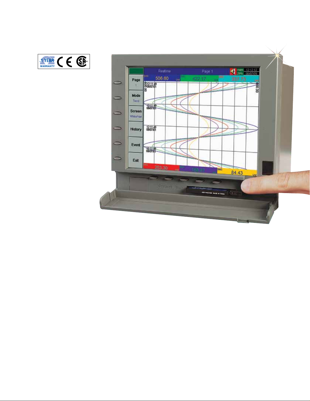
Paperless Recorder
RD8900 Series
Up to 18 Isolated
Analog Inputs
6.1" Color TFT Display
Plug and Play I/O Cards,
6 Slots
User Friendly with
Bar Graph, Numerical,
Vertical or Horizontal
Trend Display
Auto LCD Shut Off
via Infrared Detector,
Prolongs Life
and Saves Power
Stores Data on Supplied
128 MB Flash Card
Ethernet Interface
Standard with
RS232/422/485
Optional
Windows Graphical
Software Standard
and Optional Software
for Real Time View
Portable Benchtop
Option
The OMEGA® RD8900 Series
paperless recorder offers real
time display of data in a variety of
formats on a high resolution (VGA)
color TFT display. The user friendly
unit with plug and play cards can
easily be set to monitor, record, and
evaluate any application. The user
can access data on the screen,
as well as from a remote site via
the standard ethernet or optional
RS232/422/485 serial interface.
The historical data may be stored
in a flash ROM, compact flash card,
or collected in a remote host PC for
evaluation and print out. The unit’s
compact size saves space and
requires less than 7" behind a panel.
Specifications
Display: 6.1" TFT LCD, 640X480 pixel
resolution, 256 colors
Analog Input Card:
RD8900-AI1, AI2, AI3
Resolution: 18 bits
Sampling Rate: 5 times/sec
Maximum Rating:
-2 Vdc minimum, 12 Vdc maximum
(1 min for mA input)
Temperature Effect: ±1.5 µV/°C
for all inputs except mA input
±3.0 µV/°C for mA input
Sensor Lead Resistance Effect:
T/C: 0.2 µV/Ω
3-wire RTD: 2.6°C/Ω of resistance
difference of 2 leads
2-wire RTD: 2.6°C/Ω of resistance
sum of 2 leads
Burn-Out Current: 200 nA
Common Mode Rejection
Ratio (CMRR): 120 dB
Normal Mode Rejection
Ratio (NMRR): 55 dB
Isolation Breakdown Voltage
Among Channels: 430 Vac minimum
Sensor Break Detection: Sensor open
for TC, RTD and mV inputs, below 1 mA
for 4 to 20 mA input, below 0.25V for
1 to 5V inputs, unavailable for
other inputs
RD8906.
Sensor Break Responding Time:
Within 10 seconds for TC, RTD and mV
inputs, 0.1 second for 4 to 20 mA and
1 to 5V inputs
Digital Input Card
(RD8900-DI6)
Channels: 6 per card
Logic Low: -30V minimum, 0.8V max
Logic High: 2V minimum, 30V max
External Pull-Down Resistance:
1 kΩ maximum
External Pull-Up Resistance:
1.5 MΩ minimum
Digital Output Card
(RD8900-DO6)
Channels: 6 per card
Contact Form: N O (form A)
Relay Rating: 5 A/240 Vac, life cycles
200,000 for resistive load
Comm Module (RD8900-RS)
Interface: RS232 (1 unit), RS485 or
RS422 (up to 247 units)
Protocol: MODBUS® protocol RTU mode
Address: 1 to 247
S-19
Page 2
Baud Rate: 0.3 to 38.4 Kbits/sec
Data Bits: 7 or 8 bits
Parity Bit: None, even or odd
Stop Bit: 1 or 2 bits
Standard Ethernet
Communication
Protocol: Mod Bus TCP/1P,
10 BaseT; auto polarity correction for
10 BaseT
Ports: AUI (attachment unit Interface)
and RJ-45 auto-detect capability
Memory
Storage Memory on Board: 8 MB
CF Card: 128 MB standard;
optional 1 GB
Infrared Detector
Distance: Detect moving human body
within 2 m
Power: 90 to 264 Vac, 47 to 63 Hz,
60 VA, 30 W max (standard);
11 to 18 or 18 to 36 Vdc 60 VA,
30 W max (optional)
Environmental and Physical
Operating Temperature:
5 to 50°C (40 to 122°F)
Storage Temperature:
-25 to 60°C (-12 to 140°F)
Humidity: 20 to 80% RH
(non-condensing)
Insulation Resistance: 20 MΩ
minimum (at 500 Vdc)
Dielectric Strength: 3000 Vac
50/60 Hz for 1 minimum
Vibration Resistance: 10 to 55 Hz,
2
10 m/S
Shock Resistance: 30 m/S
for operation, 100 g for transportation
Dimensions:
166 W x 144 H x 174 mm D
(6.54 x 5.67 x 6.85") for panel mount
Panel Cutout: 138 x 138 mm
(5.44 x 5.44")
for 2 hour
2
(3 g)
Approval Standards
Safety: CE; EN61010-1
(IEC1010-1) Overvoltage category II,
pollution degree 2
Protective Class: IP-30 front panel,
indoor use, IP-20 housing and terminals
EMC
Emission: EN50081-1, EN61326
(EN55011 class B, EN61000-3-2,
EN61000-3-3)
Immunity: EN50082-2, EN61326
(EN61000-4-2, EN61000-4-3,
EN61000-4-4, EN61000-4-5,
EN61000-4-6, EN61000-4-11,
EN50204)
OMEGACARESM extended
warranty program is available
SM
for models shown on this
page. OMEGACARESM
Extended Warranty
Program
covers parts, labor, and
equivalent loaners. Ask your
sales representative for full
details when placing an order.
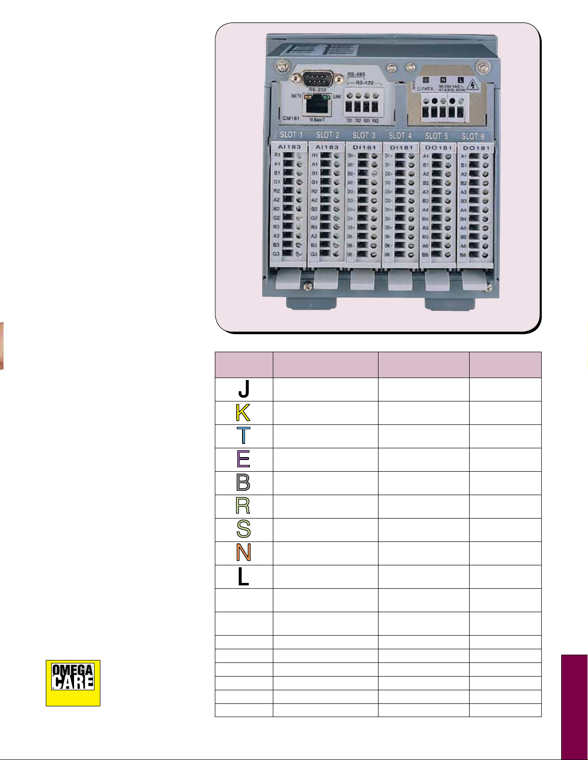
RD8906 rear view featuring plug and play I/O
cards, shown smaller than actual size.
Characteristics
Accuracy Input
Type Range @25°C Impedance
-120 to 1000°C ±1°C 2.2 MΩ
(-184 to 1832°F)
-200 to 1370°C ±1°C 2.2 MΩ
(-328 to 2498°F)
-250 to 400°C ±1°C 2.2 MΩ
(-418 to 752°F)
-100 to 900°C ±1°C 2.2 MΩ
(-148 to 1652°F)
0 to 1820°C ±2°C 2.2 MΩ
(32 to 3308°F) (200 to 1820°C)
0 to 1767.8°C ±2°C 2.2 MΩ
(32 to 3214°F)
0 to 1767.8°C ±2°C 2.2 MΩ
(32 to 3214°F)
-250 to 1300°C ±1°C 2.2 MΩ
(-418 to 2372°F)
-200 to 900°C ±1°C 2.2 MΩ
(-328 to 1652°F)
PT100 -210 to 700°C ±0.4°C 1.3 kΩ
(DIN) (-346 to 1292°F)
PT100 -200 to 600°C ±0.4°C 1.3 kΩ
(JIS) (-328 to 1112°F)
mV -8 to 70 mV ±0.05% 2.2 MΩ
mA -3 to 27 mA ±0.05% 70.5 Ω
0~1V -0.12 to 1.15V ±0.05% 32 kΩ
0~5V -1.3 to 11.5V ±0.05% 332 kΩ
1~5V -1.3 to 11.5V ±0.05% 332 kΩ
0~10V -1.3 to 11.5V ±0.05% 332 kΩ
S
S-20
Page 3
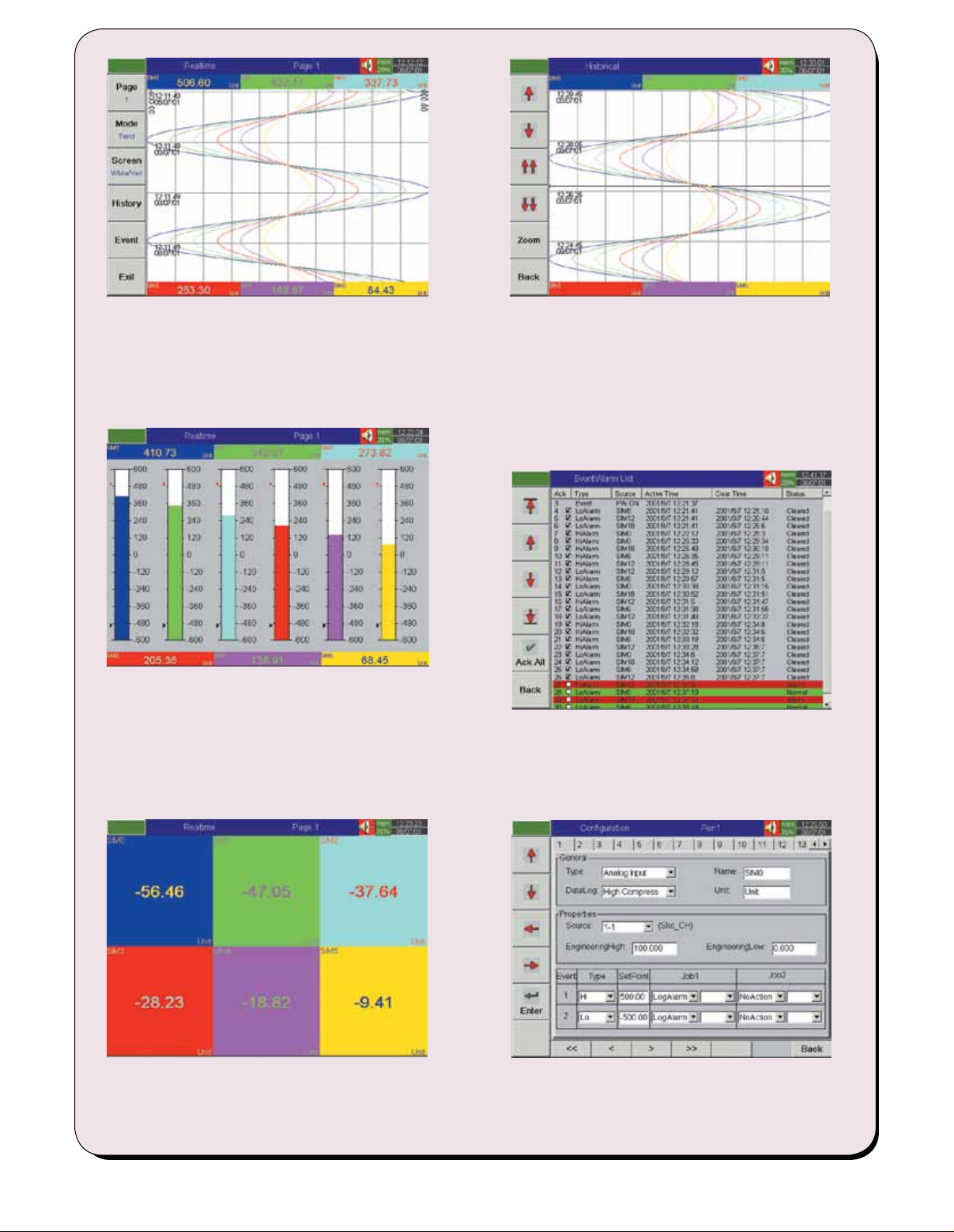
Trend Mode
Historical Mode
View max 6 real time data trends vertically
Recognize data trends easily by different colors
and tag names
Switch to other configured pages easily by “Page” function key
Display current “Time/Date” information
Remind the user of “Alarm” or “Memory Full”
Bar Graph Mode
View max 6 real time data in bar graphs
Scale individually by user in “configuration”
Display data value and tag name in different colors
together with each bar graph
Mark “Hi/Lo” alarm limits
Display current “Time/Date” information
Remind the user of the “Alarm” or “Memory Full”
Display max 6 sets of historical data simultaneously
View desired data section by “” and “” function keys
Access precise data value at a point selected by
moving the “ruler”
“Zoom” to expand/contract the display time span
View historical data trends and their respective
data values
Recognize trends easily by different colors and
individual tag names
Alarm List
List all the alarm records clearly with useful information
Browse through the alarm list or “acknowledge” alarm
easily by function keys on the vertical bar
Remind the user of the alarm status in different colors
Numerical Mode
View max 6 real time data in numbers
Display data value and tag name in different color
Mark “Hi/Lo” alarm limits
Display current “Time/Date” information
Remind the user of the “Alarm” or “Memory Full”
Configuration Mode
Configure pen (input/output, pen name, event, job.....)
Configure page (color, pen, decimal, pen width.....)
Configure timer
Configure instrument (storage media, display,
communication, time/date....)
S-21
Page 4
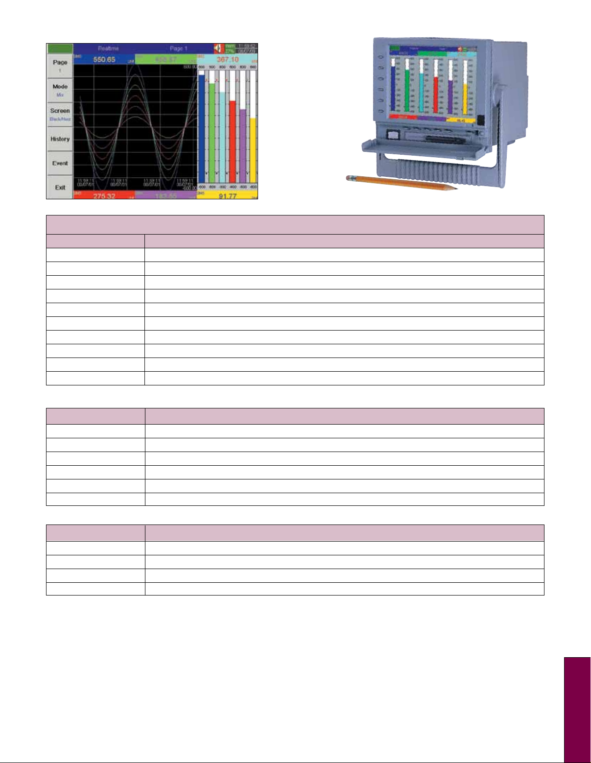
Realtime trend screen.
RD8906 with
benchop
conversion kit,
RD8900-BPS.
To Order
Model No. Description
RD8901 Recorder, 1-input, color, 5 spare I/O slots
RD8902 Recorder, 2-input, color, 5 spare I/O slots
RD8903 Recorder, 3-input, color, 5 spare I/O slots
RD8904 Recorder, 4-input, color, 4 spare I/O slots
RD8905 Recorder, 5-input, color, 4 spare I/O slots
RD8906 Recorder, 6-input, color, 4 spare I/O slots
RD8909 Recorder, 9-input, color, 3 spare I/O slots
RD8912 Recorder, 12-input, color, 2 spare I/O slots
RD8915 Recorder, 15-input, color, 1 spare I/O slot
RD8918 Recorder, 18-input, color, no spare I/O slots
Options (Field Installable in Spare I/O Slots, One Slot Required for Each Item)
Model No. Description
RD8900-AI1 Analog input card, 1-channel
RD8900-AI2 Analog input card, 2-channels
RD8900-AI3 Analog input card, 3-channels
RD8900-DI6 Digital input card, 6 inputs
RD8900-DO6 Digital output card, 6 relays/alarms
RD8900-TPS Transmitter power supply (24 Vdc 180 mA)
Accessories
Model No. Description
RD8900-DCPS DC power supply
RD8900-BPS Kit to convert to benchtop style
RD8900-SW2 Software, real time graphical via comm port
1GB-FC Memory card,1 GB compact flash (optional); standard with recorder: 128 MB
Comes complete with operator’s manual, panel mounting brackets, basic observer software for non-communication application and 128 MB
flash card.
Notes: Recorder offers Ethernet interface as standard. To include RS232/422/485 communications add “-RS” suffix for an additional cost.
Feature may be field installed by ordering RD8900-RS. To include counter/totalizer math functions add “-MATH” suffix for an additional cost.
Standard software provided with recorder supports transfer of data and recorder configuration only via the memory card. User must have a
memory card reader (not provided) connected with the host computer. The data may be read, analyzed, printed or transferred via an Excel type
file to another application. The RD8900-SW2 allows above, plus supports real time monitoring and configuration via the communications port.
Software is Windows 98, NT, 2000 and XP compatible.
Ordering Examples: RD8906, recorder with 6 inputs, plus RD8900-DO6, digital output card, plus 1GB-FC, memory card.
OCW-3, OMEGACARESM extends standard 1-year warranty to a total of 4 years.
RD8903, recorder with 3 inputs, plus RD8900-DI6, digital input card, plus RD8900-BPS, kit to convert to benchtop style, plus RD8900-SW2,
software for real time graphical via communications port.
OCW-3, OMEGACARESM extends standard 1-year warranty to a total of 4 years.
S
S-22
 Loading...