

Page 1
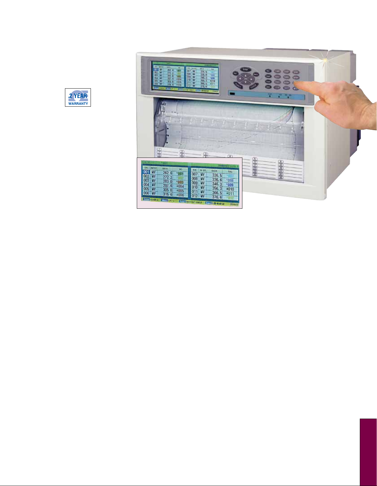
Hybrid Chart Recorder
250 mm (10")
RD5100 Series
U High Speed Scanning
at 36 Points/Sec and
High-Speed Recording
U High Accuracy of 0.05%
U Various Industrial Values
Can be Measured at
the Same Time with
Selectable Ranges
U Superior Ease of
Operation
U Engineering Port is
Provided (USB)
U Anti-Noise
Countermeasures
U Communication
Interfaces are Available
U Recording and
Calculation of Data
Communication Input
RD5100 series chart recorders are
250 mm (10") hybrid recorders with
multi-range input. Innovative design
high performance recorder provides
high accuracy, ±0.05%; high speed
scanning, 0.1 second for 36 points
and high speed recording, 1 line in
3
seconds.
and PC setting functions drastically
improved usability of recording
system.
Simple operational keys
Specifications
Input
Number of Measuring Points:
12, 24 and 36 points
Input Types: Universal (refer to the
table of inputs)
Range Setting: Input type and range
are set with front keys
Scale Setting: The minimum and
maximum values and unit are set for
each point with front keys
Setting Range: -30,000 to 30,000
Decimal Points: Optional setting
Indication Accuracy: Refer to the table
of inputs on page S-35d
Temperature Drift: 0.1% FS/ 10°C
Measuring Period: 0.1 sec/channel
Reference Junction Compensation
Accuracy:
K, E, J, T, N, Platinel II: ±0.5°C
(33°F) or less [0°C (32°F) or more
when measuring]
R, S, WRe5-WRe26, NiMo-Ni, U, L:
±1.0°C (34°F) or less [only when the
ambient temperature is 23°C (73°F)
±5°C (41°F)]
Input Resolution: Approx. 1/40,000
(standard range conversion)
Burnout: Select with/without burnout
for each input
Allowable Signal Source Resistance:
Thermocouple Inputs, DC Voltage
Input (10 mV): 500Ω or less
(without burnout)
DC Voltage Input (Except 10 mV):
100Ω or less
Resistance Thermometer Inputs:
10Ω or less/ line, three lines are
common, Pt100, JPt100
Input Resistance:
Thermocouple Input, DC Voltage
Input: Approx. 1MΩ
Maximum Input Applied Voltage:
±20 Vdc
Input Correction: Zero/span correction
and shift correction for each channel
Maximum Common Mode Coltage:
30 Vac (support LVD)
Common Mode Rejection Ratio:
130dB
RD5110
Series Mode Rejection Ratio: 50dB
(only when the peak value of noise is
below standard range)
Terminal Board: Detachable type,
removable for wire connection
Recording Specifications
Recording System: Raster scan
system, 10-color wire dot printing
Recording and Recording Color:
Analog Recording: Color can be
specified for each channel as required
10 colors (red, purple-red, orange,
brown, green, yellow-green,
blue-green, purple, purple-blue, black)
Digital Recording and Logging
Recording: Black
Message Printing: Black
List Printing: Black
Chart Paper: Fan-fold type; overall
width 318 mm (12.5"), total length
20 m (65.6'); effective recording width
250 mm (10") (analog recording)
Chart Speed: 1 to 1500 mm/H
[in 1 mm/H steps]
Skip Function: Analog recording, digital
recording and digital display can be set
independently from recording slip
Recording Compensation:
Independent setting of zero spans
are available
Display Specifications
Digital Display: Color LCD panel RGB
(640 x 240 dot)
Display Size: 149.8 W x 57.4 mm H
(5.8 W x 2.25" H)
S
S-35a
Page 2
Setting Display: Common to
digital display*
Display Contents: Digital display
Channel Display: One-point/multiple
points continuous/sequential
indication change
Display Measuring Value of
Each Channel: One-point/multiple
points continuous/sequential
indication change
Clock Display: Hour/Minute/
Second/Tag/Unit
Chart Speed Display
Status Display:
Record On: Lights during
recording; LED
Key Lock: Lights during key lock
Alarm: Lights during alarm
activated; LED
Chart End: Lights just before
record ending
Fail: Lights during unit abnormal time
* Sharing LED and setting display
Alarm Specifications
Alarm Display: Occurrence CH No,
data is displayed in red when
alarm occurs
Alarm Types: High limit, low limit
Alarm Setting Method: Individual
setting for each point four levels/
channels
Alarm Output: See option specification
Setting and Operational
Specifications
Key Types, Operation:
Func1: Switching each function
Func2: Switching each function
Enter: Setting a change of parameter
for each mode
Menu: Specifying each setting
function
Esc: Used to escape in the middle
of setting
s: Used to switch channels when
specifying the parameter on cursor
t: Used to switch channels when
specifying the parameter on cursor
s
: Used to move cursor to the right
: Used to move cursor to the left
s
Rec: Analog recording, digital
recording, printing, switching chart
ON/OFF
DataP: Digital recording of latest data
Feed: Fast-forwarding chart paper
Shift: Specifying key
. _ =: Setting characters of “. _ =”
@ + -: Setting characters of “@ + -”
0 * /: Setting parameter value 0 and
character of “* / ”
1ABC: Setting parameter value
1 and character of “ABC ”
2DEF: Setting parameter value
2 and character of “DEF”
3GHI: Setting parameter value
3 and character of “GHI”
4JKL: Setting parameter value
4 and character of “JKL”
5MNO: Setting parameter value
5 and character of “MNO”
6PQR: Setting parameter value
6 and character of “PQR”
7STU: Setting parameter value
7 and character of “STU”
8VWX: Setting parameter value
8 and character of “VWX”
9YZ: Setting parameter value
9 and character of “YZ”
Recording Operation:
Record On/Off: Recording operation
ON/OFF*
Data Print: Printing measuring data*
Feed: Fast-forwarding chart paper
* Two actions are taken to operate
General Specifications
Rated Power Voltage: 100 to 240 Vac
(universal power supply) 50/60Hz
Maximum Power Consumption: 100V A
Reference Operating Condition:
Ambient Temperature/Humidity
Range: 21 to 25°C (70 to 77°F),
45 to 65% RH
Power Voltage: 90 to 264V
Power Frequency: 50/60Hz ±2%
Attitude: Forward/Backward/left/right
within 3°
Warm-Up Time: 1 hour or longer
Normal Operating Condition:
Ambient Temperature/Humidity
Range: 0 to 40°C (32 to 104°F),
20 to 80% RH
Power Voltage: 90 to 264V
Power Frequency: 50/60Hz ±2%
Attitude: Forward/backward/left/right
within 3°
Transportation Condition: At the
packed condition on shipment from
our factory
Ambient Temperature/Humidity
Range: -20 to 60°C (-4 to 140°F),
5 to 90%RH (no dew condensation)
Vibration: 10 to 60 Hz, 4.9 m (16')/
S2 (0.5G or less)
Impact: 392 m (1.3')/S2
(approx. 40G or less)
Storage Condition:
Ambient Temperature: -20 to 60°C
(-4 to 140°F), 5 to 90% RH (no dew
condensation)
Working Condition:
Working Temperature Range:
0 to 40°C (32 to 104°F)
Working Humidity Range:
20 to 80% RH
Power Failure Protection:
Programmed parameters stored
into EEPROM memory clock circuit
sustained for 5 years or longer by a
lithium battery (at the operation of
8 hours or longer per day)
Insulation Resistance:
Between Primary Terminals and
Protective Conductor Terminals:
20MΩ or more at 500 Vdc
Between Secondary Terminals and
Protective Conductor Terminals:
20MΩ or more at 500 Vdc
Between Primary Terminals and
Secondary Terminals: 20MΩ or
more at 500 Vdc
Dielectric Strength:
Between Primary Terminals and
Protective Conductor Terminals:
1 minute at 1500 Vac
Between Secondary Terminals and
Protective Conductor Terminals:
1 minute at 500 Vac
Between Primary Terminals and
Secondary Terminals: 1 minute at
1500 Vac
Option Specifications
Options Comments
External Drive Chart 3-speed, chart stop, data printing, list
printing, message printing 5 types, operation recording
Alarm Output Mechanical relay: 12, 24, 36 points output,
max contact capacity of 100 to 240 Vac, 3 A
resistance load
External Drive Chart 3-speed, chart stop, data printing, list printing,
message printing 5 types, operation recording
Comm Interface RS422A or RS485 + Ethernet + 1a contact output
(1a contact output is contact output of mecha relay)
Chart End Output
Chart End relay output when chart paper ended
(communication interface is required)
Fail Output Fail relay output when abnormality (communication
interface is required)
Receiving 250Ω (for 20 mA) or 100Ω (for 50 mA) are externally
Resistance for mounted to measure current
Current Input
S-35b
Page 3
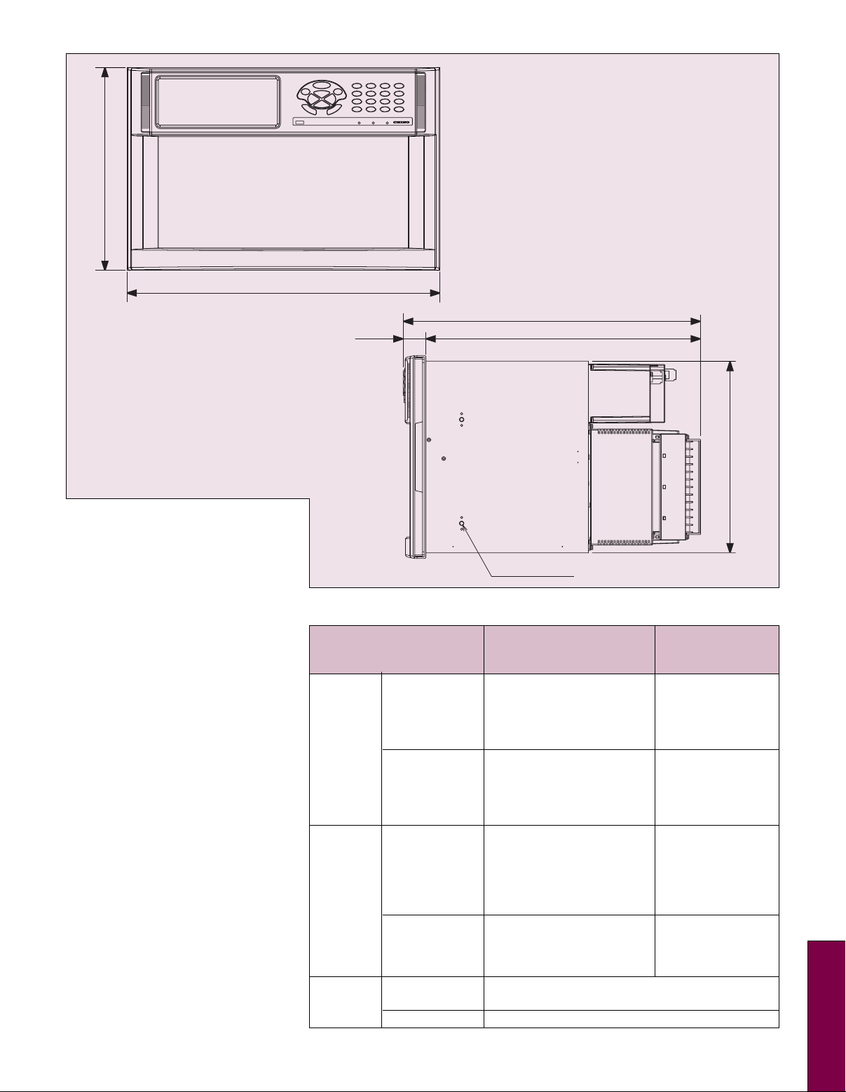
260 (10.24)
400 (15.75)
260 (10.24)
400 (15.75)
380.8 (14.99)
28.8 (1.13)
Dimensions: mm (inch)
Note 1:
Primary Terminals: Power terminal,
alarm output terminal, output relay
terminal
Secondary Terminals: Measuring
input terminal, communication
terminal, external drive terminal
Note 2: When testing insulation
resistance and dielectric strength,
please short-circuit every terminals of
primary and secondary terminals before
the test; test without short-circuiting
terminals can damage instruments
Case Assembly Material:
Door (Frame): ABS resin
Front Panel: Soda glass
Back Case: Normal steel
Color:
Door (Frame): White (equivalent to
DIC546
Front Panel: Transparent
Back Case: White (equivalent to
DIC546
Mounting: Panel mounting
Weight: About 15 kg (33 lb) (full option)
Dimensions: 400 W x 260 H x 300 mm D
(15.7 W x 10.2 H x 11.8" D)
Panel Cut Dimensions: 388 x 248 mm
(15.2 x 9.7")
Terminal Screws:
Measuring Input, Alarm
Terminals: M3.5
Power, Protective Conductor
Terminal, External Drive Terminal,
Communication Terminal: M4
Chart Paper Illumination: White LED
1
⁄2)
1
⁄2)
Communication Interface Specifications
Without
With Communication Communication
Interface Interface
Specification Ethernet10BASE-T/
100BASE-T, automated
recognition, TCP, IP, —
HTTP, exclusive
Ethernet protocol
Function Data display, parameter
setting, with browser
data display, parameter —
setting on exclusive
application
Specification RS422A, RS485,
Communication
protocol: MODBUS
communication —
specification: 9600 bps
RS422A to 19200 bps 7E1 to 8N2
RS485
Function Data display and
parameter setting
using exclusive
application
Specification Inside of front door, USB1.1, full speed
USB 12 mbps, bulk transfer, Control transfer
Function Parameter setting for exclusive application
352 (13.86)
4-M5 The opposite face is the same
—
245.6 (9.67'') x 385.6 (15.18)
S
S-35c
Page 4
U
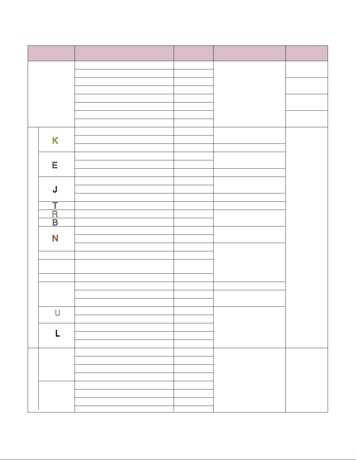
Communication Interface Specifications
Input Measuring Reference Accuracy Display
Signals Ranges Ranges Ratings Resolutions
-10.0 to 10.0 mV ±10 mV
1 µV
-20.0 to 20.0 mV ±20 mV
-40.0 to 40.0 mV ±40 mV
10 µV
DC Voltage -80 0 to 80.0 mV ±80 mV ±0.05% ±1 digit
-1.25 to 1.25V ±1.25V
±0.05% ±1 digit
100 µV
-2.5 to 2.5V ±2.5V
-5.0 to 5.0V ±5V
1 mV
-10.0 to 10.0V ±10V
-200 to 500°C (-328 to 932°F) ±20 mV
-200 to 900°C (-328 to 1652°F) ±40 mV
±0.05% ±0.5°C (±33°F)
-200 to 1370°C (-328 to 2498°F) ±80 mV ±0.05% ±1°C (±34°F)
-200 to 250°C (-328 to 482°F) ±20 mV
-200 to 500°C (-328 to 932°F) ±40 mV
±0.05% ±0.7°C (±33.2°F)
-200 to 900°C (-328 to 1652°F) ±80 mV ±0.05% ±1°C (±34°F)
-200 to 350°C (-328 to 662°F) ±20 mV
-200 to 700°C (-328 to 1292°F) ±40 mV
±0.05% ±0.7°C (±33.2°F)
-200 to 1200°C (-328 to 2192°F) ±80 mV ±0.05% ±1°C (±34°F)
-200 to 400°C (-328 to 752°F) ±20 mV ±0.05% ±0.7°C (±33.2°F)
0 to 1760°C (32 to 3200°F) ±20 mV
0 to 1300°C (32 to 2372°F) ±20 mV
±0.05% ±1°C (±34°F)
0 to 600°C (32 to 1112°F) ±20 mV
0 to 1000°C (32 to 1832°F) ±40 mV 0.1°C (32°F)
±0.1% ±0.1°C (±32°F)
0 to 1300°C (32 to 2372°F) ±80 mV
W-WRe26 0 to 2315°C (32 to 4199°F) ±80 mV
PrRh40-
PtRh20
0 to 1888°C (32 to 3430°F) ±20 mV
±0.1% ±1°C (±34°F)
NiMo-Ni -50 to 1310°C (-58 to 2390°F) ±80 mV
0 to 500°C (32 to 932°F) ±20 mV ±0.1% ±0.1°C (±32°F)
Platinel II 0 to 950°C (32 to 1742°F) ±80 mV
0 to 1395°C (32 to 2543°F) ±80 mV
±0.1% ±1°C (±34°F)
-200 to 350°C (-328 to 662°F) ±20 mV
-200 to 600°C (-328 to 1112°F) ±40 mV
-200 to 350°C (-328 to 662°F) ±20 mV
±0.05% ±1°C (±34°F)
-200 to 700°C (-328 to 1292°F) ±40 mV
-200 to 900°C (-328 to 1652°F) ±80 mV
-50 to 50°C (-58 to 122°F) 50Ω
-100 to 130°C (-148 to 266°F) 100Ω
Pt100
-200 to 250°C (-328 to 482°F) 200Ω
-200 to 550°C (-328 to 1022°F) 300Ω
-50 to 50°C (-58 to 122°F) 50Ω
RTDs Thermocouples
-200 to 250°C (-328 to 482°F) 200Ω
JPt100
-100 to 130°C (-148 to 266°F) 100Ω
±0.05% ±0.3°C (±32.5°F)
0.1°C (32°F)
-200 to 550°C (-328 to 1022°F) 300Ω
Note 1: Ambient temperature/humidity range: 23°C ±2°C
Note 2: For thermocouple input, the accuracy of reference junction compensation is not included with the accuracy ratings.
Note 3: Accuracy rating is the percentage of measuring range K, E, J, T, R, S, B, N: IEC584, JIS C 1602-1995; W-Wre26, Wre5-WRs26,
PtRh40-PtRh20, NiMo-Ni, Platinel?: ASTM Vol.14.03; U(Cu-CuNi), L(Fe-CuNi): DIN43710; Pt100: IEC751, JIS C 1604-1997;
JPt100: JIS C 1604-1981, JIS C 1606-1986
S-35d
Page 5
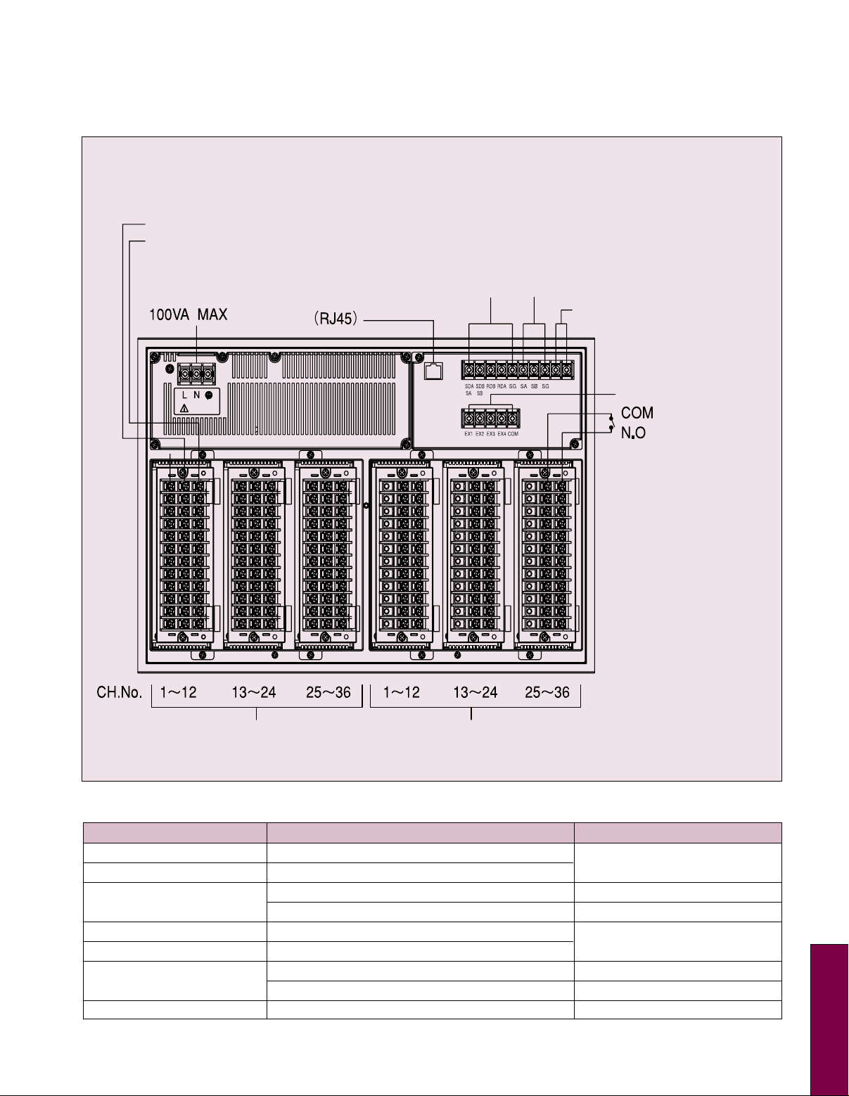
Terminal Board
Thermocouple DC voltage (-) resistance thermometer B
Thermocouple DC voltage (+) resistance thermometer A
Power terminal
100 to 240V 50/60 Hz
Resistance thermometer terminal B
Upper Comm: RS422A/RS485 terminal
Comm. between instruments RS485 terminal
Ethernet connector
Output relay terminal
Ext. drive terminal
Measuring input terminal
Exceptions of Accuracy Ratings
Input Signals Measuring Ranges Accuracy Ratings
K, E, J, T, L -200 to 0°C (-328 to 32°F)
R, S 0 to 400°C (32 to 752°F)
400 to 800°C (752 to 1472°F) ±0.15% ±1 digit
U -200 to 0°C (-328 to 32°F)
W-WRe26 0 to 300°C (32 to 572°F)
PrRh40-PtRh20
300 to 800°C (572 to 1472°F) ±0.8% ±1 digit
NiMo-Ni -50 to 100°C (-58 to 212°F) ±0.2% ±1 digit
Note: Refer to thermocouple input accuracy is calculated based on standard range, see previous page.
0 to 400°C (32 to 752°F) None
B
0 to 300°C (32 to 572°F) ±1.5% ±1 digit
Alarm output terminal
±0.2% ±1 digit
±0.3% ±1 digit
S-35e
S
Page 6
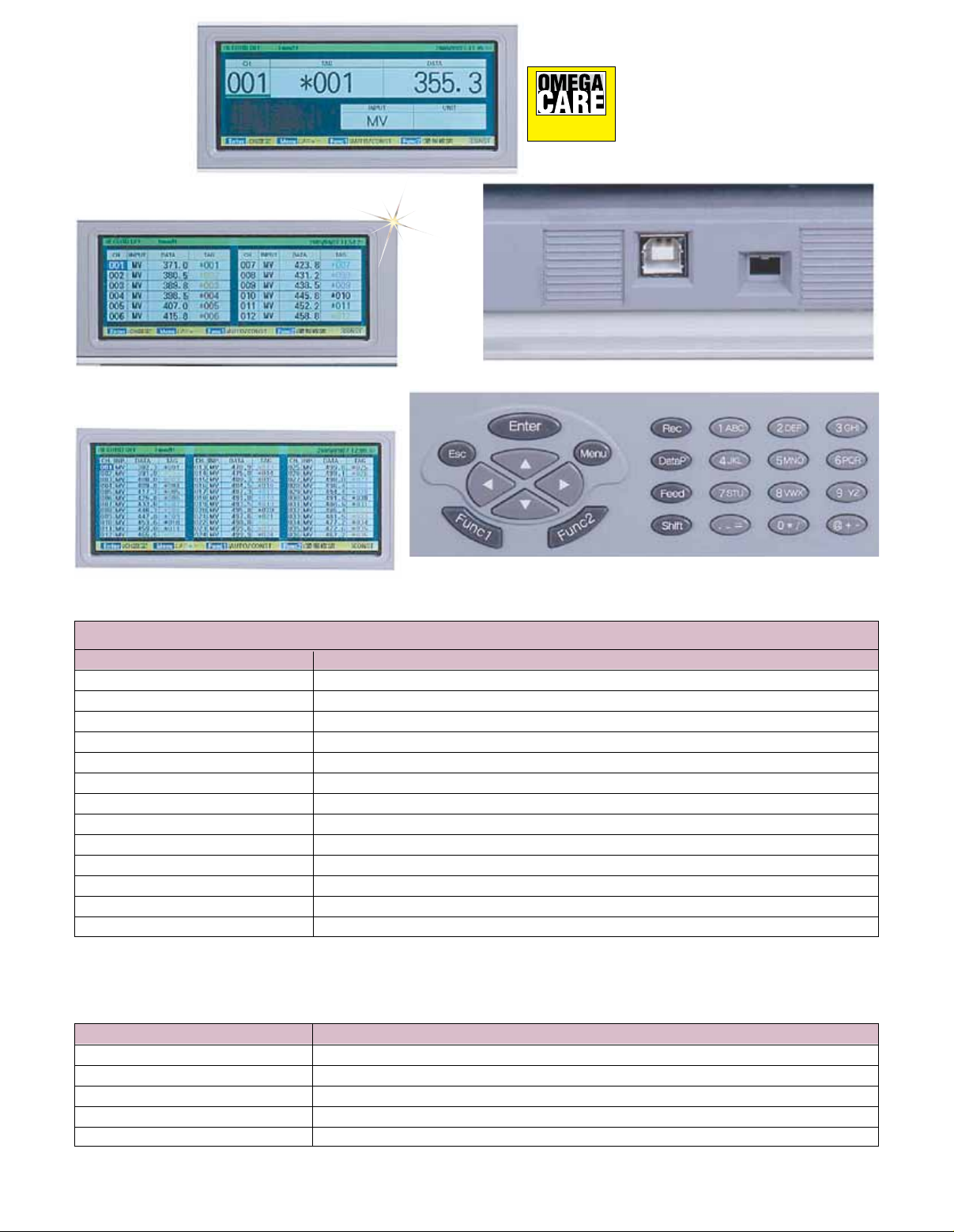
1 channel display
Extended Warranty
Program
SM
OMEGACARESM extended warranty program
is available for models shown on this page.
Ask your sales representative for full details
when placing an order. OMEGACARE
covers parts, labor and equivalent loaners.
SM
12 channels simultaneous display
36 channels simultaneous display
Engineering and USB port
Operation key pad
To Order
Model No. Description
RD5110 250 mm (10") 12-points hybrid chart recorder
RD5120 250 mm (10") 24-points hybrid chart recorder
RD5130 250 mm (10") 36-points hybrid chart recorder
RD5111 250 mm (10") 12-points with 12 alarms hybrid chart recorder
RD5112 250 mm (10") 12-points with 24 alarms hybrid chart recorder
RD5121 250 mm (10") 24-points with 12 alarms hybrid chart recorder
RD5122 250 mm (10") 24-points with 24 alarms hybrid chart recorder
RD5131 250 mm (10") 36-points with 12 alarms hybrid chart recorder
RD5132 250 mm (10") 36-points with 24 alarms hybrid chart recorder
RD5133 250 mm (10") 36-points with 36 alarms hybrid chart recorder
RD5110-COMM 250 mm (10") 12-points hybrid chart recorder with communications
RD5120-COMM 250 mm (10") 24-points hybrid chart recorder with communications
RD5130-COMM 250 mm (10") 36-points hybrid chart recorder with communications
Comes complete with operator’s manual.
Ordering Example: RD5110, 250 mm (10") hybrid chart recorder.
OCW-3, OMEGACARESM extends standard 2-year warranty to a total of 5 years.
Accessories
Model No. Description
RD5100-RC 10-color ribbon cassette, package of 5
RD5100-CP-0/100 Z-fold chart paper 250 mm x 20 m (9.8" x 65.6'), case of 15
RD9900-ZAILA ZAILA data analysis software
RD2800-PASS Parameter programming software
RD2800-KIDS Data acquisition software
S-35f
 Loading...