

Page 1
Paperless Recorders
RD1000/RD2000/RD3000
Series
TM
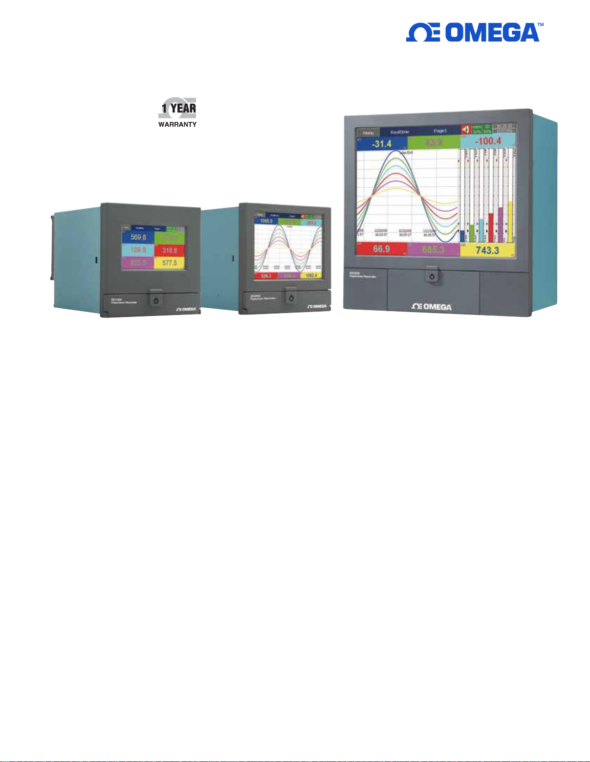
RD1000, 4.3" display
Color TFT Touch
U
Screen Display:
4.3", 5.6" and 12.1"
U Expandable Inputs
and Outputs via Plug
and Play I/O Cards:
RD1000/2000 Series–
4 Slots; RD3000 Series–
16 Slots
U Analog Inputs:
RD1000 Series–Up to 6
RD2000 Series–Up to 24
RD3000 Series–Up to 48
U User Friendly with
Bar Graph, Numerical,
Vertical or Horizontal
Trend Display
U Ethernet Interface
Standard with Optional
RS232/422/485
Communications
U Built-In Web Server for
Remote Data Monitoring
RD2000, 5.6" display
All models shown
smaller than actual size.
U Stores Data on 256 MB
Internal Flash Memory
U Windows® Graphical
Software Standard and
Optional Software for
Real Time Monitoring
The RD1000/2000/3000 Series
paperless recorders offer real
time display of data in a variety of
formats on a high resolution TFT
touch screen display. The user
friendly unit with plug and play cards
can easily be set to monitor, record,
and evaluate any application. The
user can access data on the screen,
as well as from a remote site via
the standard Ethernet, Web Server
or optional RS232/422/485 serial
interface. The historical data may
be stored in a flash ROM, compact
flash card, or collected in a remote
host PC for evaluation and print
out. The unit’s compact size saves
space and minimizes depth required
behind the panel.
1
RD3000, 12.1" display
Hardware Features
• RD1000 Series: 3 or 6 Universal
Analog Inputs and 24 Optional
External Channels
• RD2000 Series: 6, 12, 18 or 24
Universal Analog Inputs and 48
Optional External Channels
• RD3000 Series: 6, 12, 18, 24, 30,
36, 42 or 48 Universal Analog Inputs
and 96 Optional External Channels
• TFT Color LCD, High Resolution
Touch Screen
• 100 Millisecond Sample Rate and
Data Logging
• High Accuracy 24-Bit A/D Analog
Input
• 16-Bit D/A Analog Output
• Digital Input, 100 Hz Maximum
• Plug and Play I/O cards (AI, AO, DI,
DO) for Easy Expansion
• On-Board SD Card Slot for Internal
Memory
• USB Slot for External Storage
• 171 mm Short Depth Behind Panel
• Standard Ethernet with Optional
RS232 or RS422/RS485
Communications
• Two USB Host Ports for
Downloading Data or
Connect to Printer
• IP65 (NEMA 4X) Water-Resistant
Page 2
Firmware and PC Software Features
• Free Basic Software for Conguration, Historical Viewer
• Optional Extensive Data Acquisition Studio Software—for
Conguration, Historical Viewer and Real Time Viewer
• Circular Trends in RD3000 Series
• Additional Panel Studio Software for Editing and Customizing
Displays
• Display Values in Digital, Real Time Trends, Historical Trends, Bar
Graphs
• Real Time and Historical Alarms
• Event Management, Jobs Linked with Events
• Reports (Daily, Weekly and Monthly)
• Timers – Optional: Counters, Totalizers, Math Channels and CFR-21
• Customized Messages for Alarms
• Alarms by Email Directly from Paperless Recorder
• Batch Control, Log Data in Batches
• 100 msec Data Logging and Historical Data Archival Tools
• Display Screen Rotation
• Dynamic Data Exchange via PC Software
• Search Data with Reference to Time and Period, then Export to
Spreadsheets
• Data Logging by Value Change or Time Base
• Start/Stop Data Logging Functions Which Can Be Linked with Real
Time Clock or Events
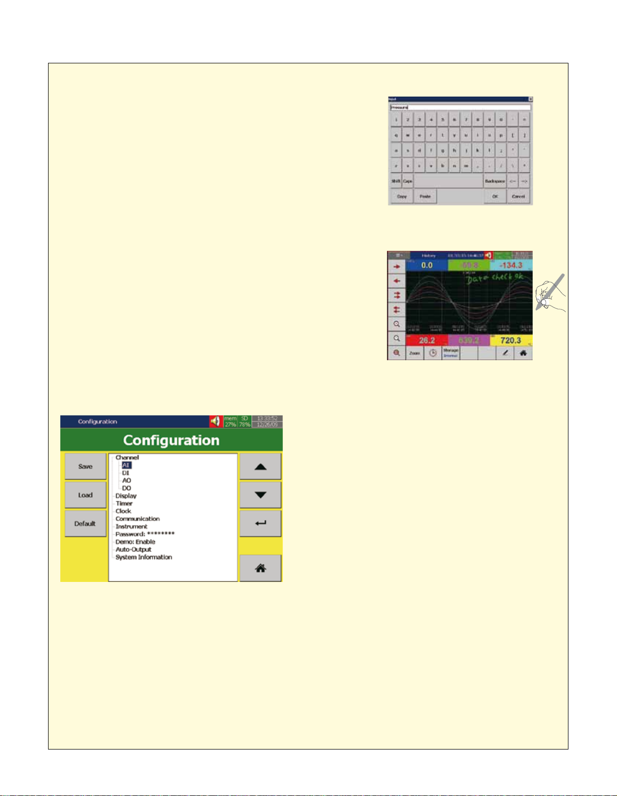
Recorder Input Name and Description
Screen—Standard Firmware
Input name and description:
Large entry fields allow users to
key in many characters.
Recorder Touch Screen
Touch-screen allows easy handwriting
of notes and messages.
Recorder Configuration Screen
AI: Analog input logging speed can be set from 100 ms,
1, 2, 5, 10, 20, 30 sec/dot;, 1, 2 min/dot
DI: Digital input is offered either normal logic or high
frequency pulse
AO: In analog output, mA or V and its expression can
be defined
DO: Digital output/relay output can be enabled. Each DO
card has 6 relays
Display: Various display speeds are available from 100 ms
1, 2, 5, 10, 20, 30 sec/dot, or 1, 2, 10, 30 min/page,
1, 2, 4, 8, 12 hour/page, or 1 day/page
Timer: Timer in countdown, repeat countdown, daily,
weekly or monthly base, and various jobs can be defined
Clock: Date style of mm/dd/yy or dd/mm/yy, time
Configuration in tree layout is easy to operate.
Communication: Web server and email functions are available in communication in standard firmware
Instrument: Brightness adjustment and screen saver are available in instrument
Password: If normal security is chosen, then only one password is offered. If high security of CFR-21 is
chosen, then 9 levels of password can be defined
Demo: Enable or disable the demonstration
Auto-output: Automatic output can be set to specify the printer, to print historical data & report data in
specified period of time
System information: Gives firmware version number, internal and external memory status, IP address, and IO
card status of each slot
Web Server: Available with all the recorders as a standard feature. When this feature is enabled the user can
access real-time trends, data, events and alarms wherever an internet connection is available
synchronize via internet, and daylight saving time can
be defined
,
2
Page 3
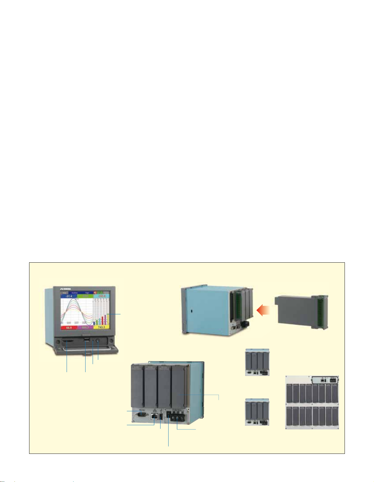
Expandable Input
RD2000 Front view
RD2000 Back view
Touch LCD display
RESET
START/STOP
1st USB hostSD Slot
®
RD2000 Back view
IO modules
Power terminals
RS-232/422/485
(option)
Ethernet port
(standard)
2nd USB host
(standard)
Power switch
(option for panel mount)
(standard for portables)
Touch LCD display
RESET
START/STOP
1st USB hostSD Slot
IO modules easy for expansion
RD1000
(4 Slots, up to 6 AI)
RD2000
(4 Slots, up to 24 AI)
RD3000
(16 Slots, up to 48 AI)
®
RD1000
(4 Slots, up to 6 AI)
RD2000
(4 Slots, up to 24 AI)
RD3000
(16 Slots, up to 48 AI)
RD3000
(16 Slots, up to 48 AI)
RD2000
(4 Slots, up to 24 AI)
RD2000 Back view
IO modules
Power terminals
RS-232/422/485
(option)
Ethernet port
(standard)
2nd USB host
(standard)
Power switch
(option for panel mount)
(standard for portables)
Touch LCD display
RD3000
(16 Slots, up to 48 AI)
and Output Cards
Each recorder is equipped with rear
expansion slots (RD1000/RD2000
Series has 4 slots, RD3000 Series
has 16 slots) which work exibly
with the following plug and play I/O
cards:
Analog Input Cards (RD1000-3AI
& RD1000-6AI): These two cards
are used for 3 or 6-channel analog
inputs. Each input is isolated from
each other to avoid noise and to
ensure stable measurement.
Relay Output Card (RD1000-6R):
Each card includes 6 alarm relays.
Contacts are rated 5 A/240 Vac
Digital Input Card (RD1000-6DI):
Each card includes 6 channels.
Logic Low: -5V minimum, 0.8V
maximum, Logic High: 3.5V
minimum, 24V maximum
Combination Relay Output
and Digital Input Card
(RD1000-3R-3DI): Each card
includes 3 digital Inputs and 3 relay
outputs. For digital inputs, Logic
Low: -5V minimum, 0.8V maximum,
Logic High: -3.5V minimum, 24V
maximum. For relay outputs, the
contacts are rated 5 A/240 Vac.
Analog Output Card (RD10006AO): Each card includes 6
channels. They are used for 4 to 20
mA, 0 to 20 mA current output, 0
to 5 V, 1 to 5 V, 0 to 10 Vdc voltage
output.
Communication
The standard communication
interface is Ethernet with
protocol IEEE 802.3 – 10/100
Base T. RS232/422/485 serial
communications is optional.
SPECIFICATIONS
GENERAL
Display: LCD, 65K color
Resolution: RD1000: 480 x 272;
RD2000: 640 x 480; RD3000: 1024 x 768
Backlight: LED
MTBF Backlight @ 25˚C: RD1000,
RD2000: 30,000 hrs; RD3000: 60,000 hrs
CPU: ARM Cortex-A8, 1 GHz
Internal Flash Memory: 256 MB
SD Card Slot: Standard
USB Host: 2 ports (one front, one back)
Start/Stop Key: Start/stop recording and
turn off display only (for quick re-start),
does not turn off power to the unit
Web Server: The recorder trend and
digital data can be viewed in any place in
the world with the recorder connected to
Internet with a fixed IP address
Multilingual Programming:
19 languages including English,
Japanese, Chinese (simplied,
traditional), French, German, Spanish,
Swedish, Danish, Italian, Polish, Russian,
Dutch, Korean, Thai, Turkish, Portuguese,
Brazil Portuguese and Czech
PC Software: Standard software
supplied for historical data viewing and
configuration; optional Data Acquisition
Studio software for real-time monitoring;
supports Windows XP/Vista/7/8 (32-bit
and 64-bit)
Real Time Clock
Accuracy vs.
Temperature Inside
of Housing: 18 sec typical error per
month (10 to 40˚C); 52 sec typical error
per month at 0˚C or 50˚C; 107 sec
typical error per month at -10˚C or 60˚C
Power: 90 to 250 Vac, 47 to 63 Hz,
52 VA, 26 W max; 11 to 36 Vdc, 26 VA,
26 W max (optional)
ANALOG INPUT CARDS
(RD1000-3AI AND RD1000-6AI)
Channels:
RD1000-3AI: 3 channels
RD1000-6AI: 6 channels
Resolution: 24 bits
Sampling Rate: 10 times/second
Maximum Rating:
RTD Input: ±20V
Thermocouple and Voltage Input: ±65V
Current (mA) Input: ±10V
Temperature Effect: ±0.1 µV ±15 ppm
of reading for all inputs except mA,
±30 ppm of reading for mA input
Sensor Lead Resistance Effect:
•Thermocouple:0.32 ppm of
reading/Ω
• 3-WireRTD:2.6˚C/Ω of resistance
difference of two leads (based on
˚C measurement temperature for
Pt100)
•2-WireRTD:2.6˚C/Ω of resistance
sum of two leads (based on ˚C
measurement temperature for
Pt100)
• Burn-OutCurrent:10µA
Expandable modules of inputs and outputs
IO modules easy for expansion
3
Page 4
Common Mode
W
U
Rejection Ratio
(CMRR): 120 dB
Normal Mode
Rejection Ratio
(NMRR): 55 dB
Isolation Breakdown Voltage Between
Channels: 1500 Vac min
Sensor Break Detection: Sensor
opened for thermocouple, RTD and
mV inputs; below 1 mA for 4 to 20 mA
input, below 0.25V for 1 to 5V inputs,
unavailable for other inputs
Sensor Break Response Time:
Within 1 second for thermocouple,
RTD and mV inputs; 0.1 second for 4
to 20 mA and 1 to 5V inputs
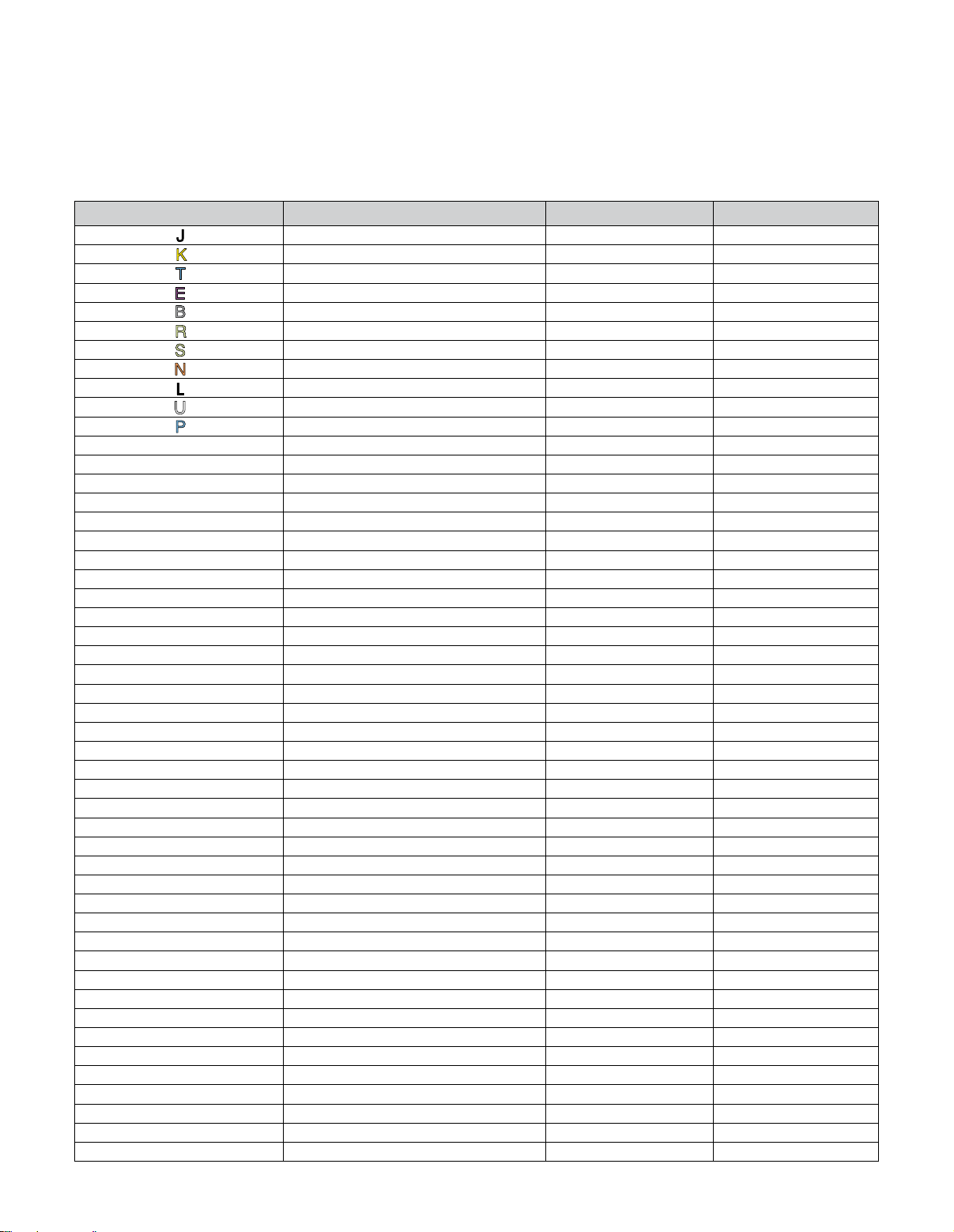
Analog Input Types and Ranges
Type Range Accuracy @ 25˚C Input Impedance
J -120 to 1000˚C (-184 to 1832˚F) ±1˚C 3.12 MΩ
K -200 to 1370˚C (-328 to 2498˚F) ±1˚C 3.12 MΩ
T -250 to 400˚C (-418 to 752˚F) ±1˚C 3.12 MΩ
E -100 to 900˚C (-148 to 1652˚F) ±1˚C 3.12 MΩ
B 0 to 1820˚C (32 to 3308˚F) ±2˚C (200 to 1820˚C) 3.12 MΩ
R 0 to 1768˚C (32 to 3214˚F) ±2˚C 3.12 MΩ
S 0 to 1768˚C (32 to 3214˚F) ±2˚C 3.12 MΩ
N -250 to 1300˚C (-418 to 2372˚F) ±1˚C 3.12 MΩ
L -200 to 900˚C (-328 to 1652˚F) ±1˚C 3.12 MΩ
U -200 to 600˚C (-328 to 1112˚F) ±1˚C 3.12 MΩ
P 0 to 1395˚C (32 to 2543˚F) ±1˚C 3.12 MΩ
W5 0 to 2315˚C (32 to 4199˚F) ±1˚C 3.12 MΩ
W3 0 to 2315˚C (32 to 4199˚F) ±1˚C 3.12 MΩ
LR -200 to 800˚C (-328 to 1472˚F) ±1˚C 3.12 MΩ
A1 0 to 2500˚C (-32 to 4532˚F) ±1˚C 3.12 MΩ
A2 0 to 1800˚C (-32 to 3272˚F) ±1˚C 3.12 MΩ
A3 0 to 1800˚C (-32 to 3272˚F) ±1˚C 3.12 MΩ
M -200 to 100˚C (-328 to 212˚F) ±1˚C 3.12 MΩ
Pt50 (α = 0.00385) -200 to 850˚C (-328 to 1562˚F) ±0.4˚C 2.0 KΩ
Pt100 (α = 0.00385) -200 to 850˚C (-328 to 1562˚F) ±0.4˚C 2.0 KΩ
Pt200 (α = 0.00385) -200 to 850˚C (-328 to 1562˚F) ±0.4˚C 2.0 KΩ
Pt500 (α = 0.00385) -200 to 850˚C (-328 to 1562˚F) ±0.4˚C 2.0 KΩ
Pt1000 (α = 0.00385) -200 to 350˚C (-328 to 662˚F) ±0.4˚C 2.0 KΩ
Pt50 (α = 0.00391) -200 to 850˚C (-328 to 1562˚F) ±0.4˚C 2.0 KΩ
Pt100 (α = 0.00391) -200 to 850˚C (-328 to 1562˚F) ±0.4˚C 2.0 KΩ
JPT50 (α = 0.003916) -200 to 600˚C (-328 to 1112˚F) ±0.4˚C 2.0 KΩ
JPT100 (α = 0.003916) -200 to 600˚C (-328 to 1112˚F) ±0.4˚C 2.0 KΩ
JPT200 (α = 0.003916) -200 to 600˚C (-328 to 1112˚F) ±0.4˚C 2.0 KΩ
JPT500 (α = 0.003916) -200 to 600˚C (-328 to 1112˚F) ±0.4˚C 2.0 KΩ
JPT1000 (α = 0.003916) -200 to 350˚C (-328 to 662˚F) ±0.4˚C 2.0 KΩ
Cu50 (α = 0.00426) -50 to 200˚C (-58 to 392˚F) ±0.4˚C 2.0 KΩ
Cu100 (α = 0.00426) -50 to 200˚C (-58 to 392˚F) ±0.4˚C 2.0 KΩ
Cu50 (α = 0.00428) -180 to 200˚C (-292 to 392˚F) ±0.4˚C 2.0 KΩ
Cu100 (α = 0.00428) -180 to 200˚C (-292 to 392˚F) ±0.4˚C 2.0 KΩ
Ni100 (α = 0.00617) -60 to 180˚C (-76 to 356˚F) ±0.4˚C 2.0 KΩ
Ni200 (α = 0.00617) -60 to 180˚C (-76 to 356˚F) ±0.4˚C 2.0 KΩ
Ni500 (α = 0.00617) -60 to 180˚C (-76 to 356˚F) ±0.4˚C 2.0 KΩ
Ni1000 (α = 0.00617) -60 to 180˚C (-76 to 356˚F) ±0.4˚C 2.0 KΩ
Cu10 (α = 0.00427) -200 to 260˚C (-328 to 500˚F) ±1.0˚C 2.0 KΩ
±20 mA -26 to 26 mA ±0.05% 75 Ω
±60 mV -122 to 122 mV ±0.05% 3.12 MΩ
±200 mV -243 to 243 mV ±0.05% 3.12 MΩ
±1V -1.58 to 1.58V ±0.05% 3.12 MΩ
±2V -3.16 to 3.16V ±0.05% 3.12 MΩ
±6V -6.32 to 6.32V ±0.05% 3.12 MΩ
±20V -25.3 to 25.3V ±0.05% 3.12 MΩ
±50V -50.6 to 50.6V ±0.05% 3.12 MΩ
0.4 to 2V -3.16 to 3.16V ±0.05% 3.1 2MΩ
1 to 5V -6.32 to 6.32V ±0.05% 3.12 MΩ
4
Page 5
DIGITAL INPUT CARD
(RD1000-6DI)
Channels: 6 per card
Logic Low: -5V min, 0.8V max
Logic High: 3.5V min, 24V max
External Resistance:
Pull-Down: 1 KΩ max
Pull-Up: 1.5 MΩ min
Frequency: 100 Hz max
RELAY OUTPUT CARD
(RD1000-6R)
Channels: 6 per card
Contact Form: NO/NC (form C)
Relay Rating: 5A/240 Vac; life cycles
200,000 for resistive load
ANALOG OUTPUT CARD
(RD1000-6AO)
Channels: 6 per card
Range: 4 to 20 mA, 0 to 20 mA,
0 to 5V, 1 to 5V, 0 to 10V
Resolution: 16-bits
Accuracy: ±0.05% of span
±0.0025% /˚C
Load Resistance: 0 to 500 Ω
(current), 10 KΩ min (voltage)
Output Regulation: 0.01% for full
load change
Output Setting Time: 0.1 second
(stable to 99.9%)
Isolation Breakdown Voltage:
1500 Vac at 50/60 Hz for 1 minute
Integral Linearity Error: ±0.005% of
span
Temperature Effect: ±0.0025% of
span/˚C
STANDARD ETHERNET
COMMUNICATIONS
Protocol: Modbus® TCP/IP,
10/100 Base T
Ports: AUI (Attachment Unit Interface)
and RJ-45, auto-detect capability
WEBSERVER
Description: Used to view the
RD1000/RD2000/RD3000 Series
paperless recorder from a remote
location via the Internet
Browser Requirements: Internet
Explorer 10 or higher, Google Chrome
IP Address: A Static IP address is
required for the recorder. Obtain a
Static IP address from your Internet
service Provider (ISP). This IP
address should be unique.
TM
COMM MODULE
(OPTIONAL RS232/422/485
COMMUNICATIONS)
Interface: RS232 (1 unit), RS485 or
RS422 (up to 247 units)
Protocol: Modbus protocol RTU mode
Address: 1 to 247
Baud Rate: 9.6 to 115.2 K bits/sec
Measured Data Bits: 7 or 8-bits
Parity Bit: None, even or odd
Stop Bit: 1 or 2 bits
ENVIRONMENTAL
AND PHYSICAL
Operating Temperature: 0 to 50˚C
(32 to 122˚F)
Storage Temperature: -30 to 70˚C
(-22 to 158˚F)
Humidity: 20 to 90% RH (non-
condensing), maximum relative
humidity of 90% RH is for ambient
temperature up to 38˚C (100˚F)
decreasing linearly to 50% RH at
50˚C (122˚F)
Altitude: 2000 M maximum
Insulation Resistance: 20 MΩ min @
500 Vdc
Dielectric Strength: 2300 Vac,
50/60 Hz for 1 minute between power
terminal and earth
Vibration Resistance: 10 to 55 Hz,
10m/s² for 2 hours
RD1000
RD2000
RD3000
Shock Resistance: 30m/s² (3g) for
operation, 20 g for transportation
Operation Position: no inclined
restriction
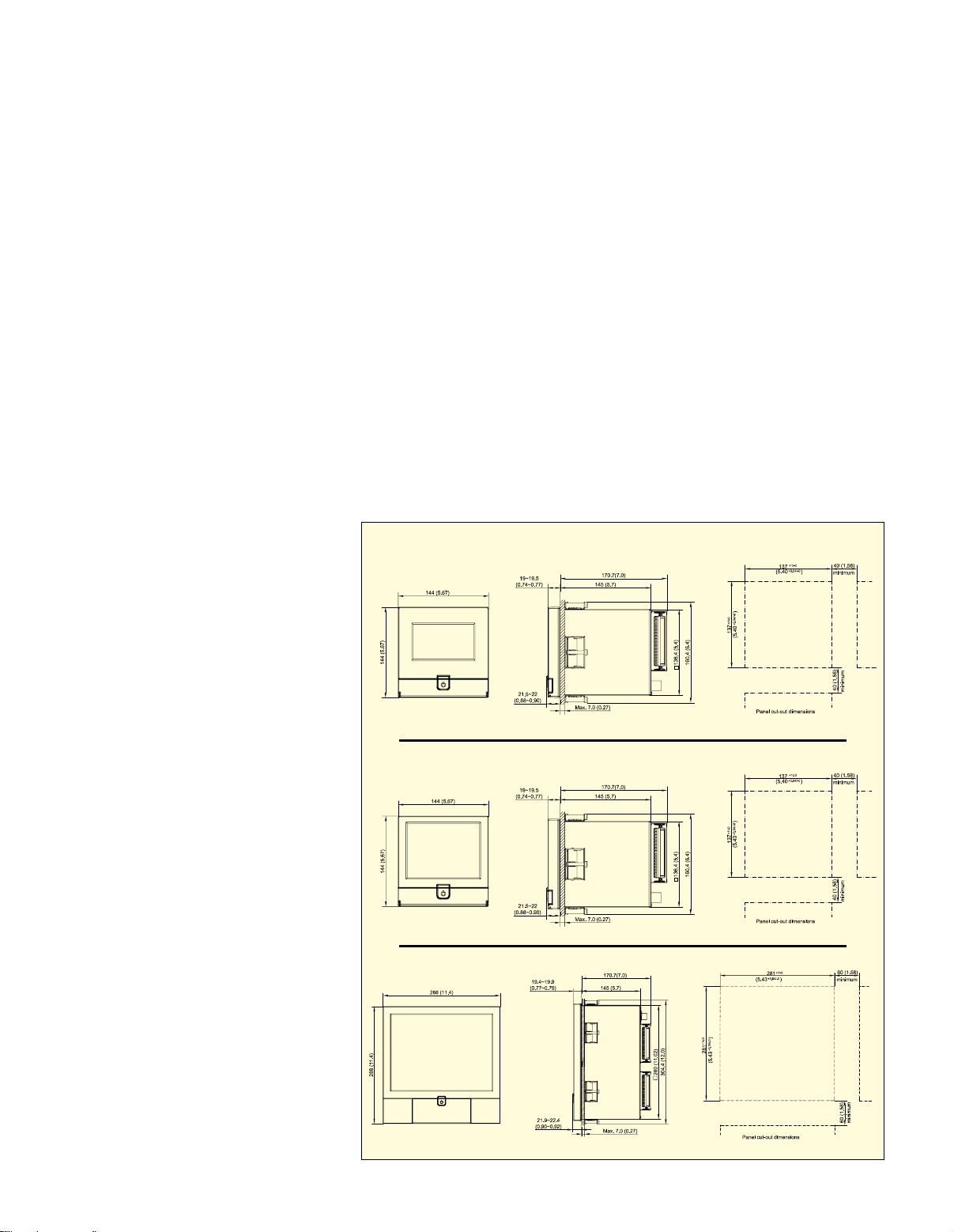
Dimensions (Panel Mount Style):
RD1000/RD2000 Series:
144 H x 144 W x 189 mm D
(5.67 x 5.67 x 7.44")
RD3000 Series:
288 H x 288 W x 189 mm D
(11.34 x 11.34 x 7.44")
Standard Panel Cutout:
RD1000/RD2000 Series:
137 x 137 mm (5.39 x 5.39")
RD3000 Series: 281 x 281 mm
(11.06 x 11.06")
Mounting Depth Behind Panel:
171 mm (6.73")
Enclosure: IP65 front panel for indoor
use; IP20 housing and terminals
Dimensions: mm (in)
5
Page 6
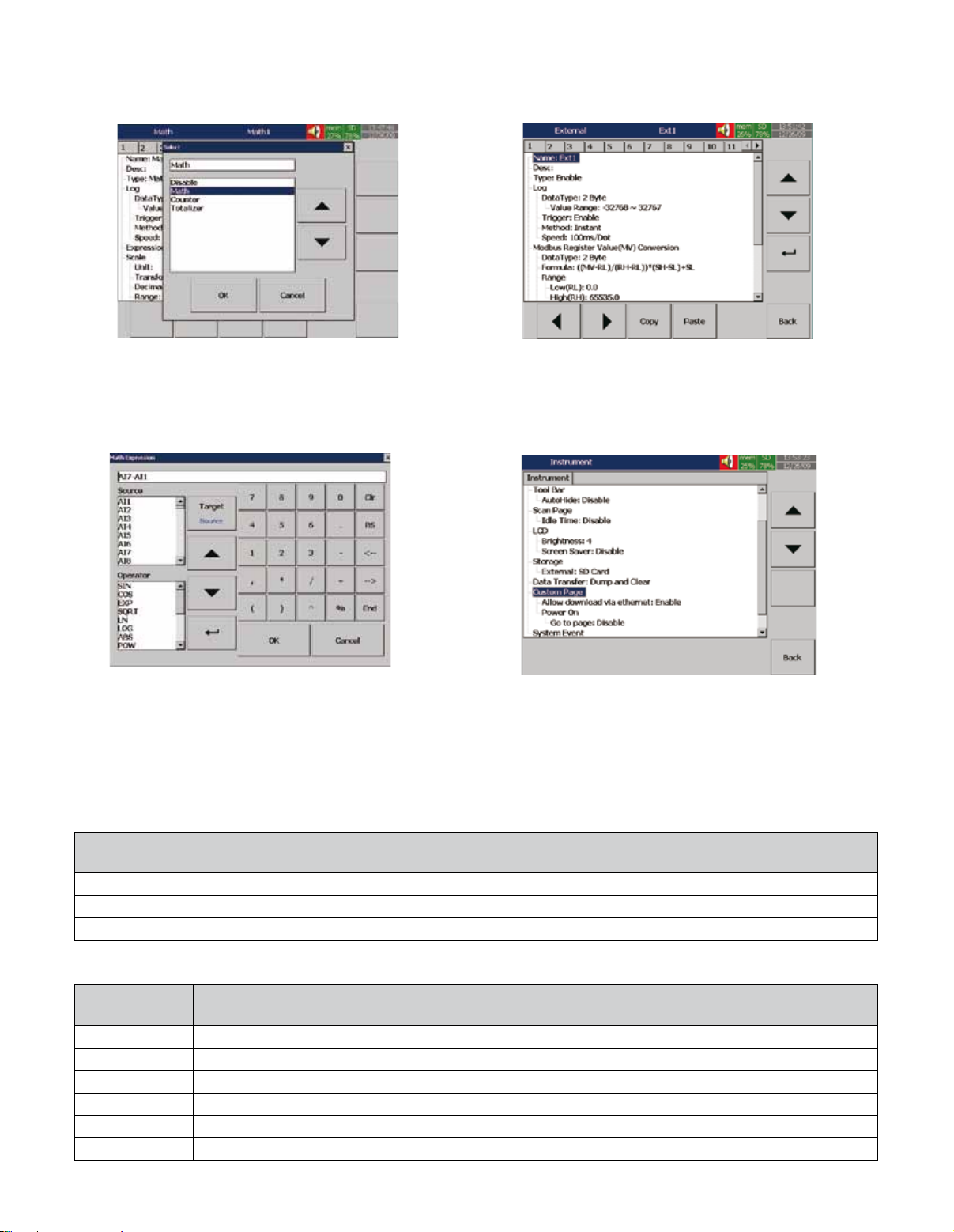
Math
Plus Version of Firmware—Supports Additional Features Including Math
Channels, External Channels, Custom Display, Batch Control and FDA 21
CFR Part 11 Compliance
External Channels.
Includes Math, Counter and Totalizer.
Math expression is easily keyed in.
Firmware Options (for Additional Cost)
Add Suffix to
Model No. Description
-FW1
-FW2
-FW3
Plus version 1 with extra math, external channels, batch and FDA 21 CFR Part 11
Plus version 2 with custom edited display and Panel Studio editing software
Plus version 3 includes all items in Plus versions 1 and 2
Besides AI and DI inputs, these recorders accept
inputs through communication called External
Channels. RD1000, RD2000, and RD3000 Series
recorders can accept up to 24, 48 and 96 channels
respectively.
Custom Edited Display.
In Plus versions, Panel Studio software allows
the user to edit the specific display instead of the
standard display. It can then be downloaded to the
recorder.
Batch Control: Batch production record is
constantly required for more strict production, for
example food and drugs.
FDA 21 CFR part 11: This feature complies with U.S.
Food and Drug Administration. All data can not be
manipulated after recording.
Mounting Options (for Additional Cost)
Standard Configuration is Panel Mount, No Power Cord, No Power Switch
Add Suffix to
Model No. Description
-1
-2
-3
-4
-5
-6
Panel mount, no power cord, power switch (no additional cost)
Portable, power cord, power switch
Portable, VDE power cord, power switch
Portable, SAA power cord, power switch
Portable, BS power cord, power switch
Portable, GB power cord, power switch
6
Page 7
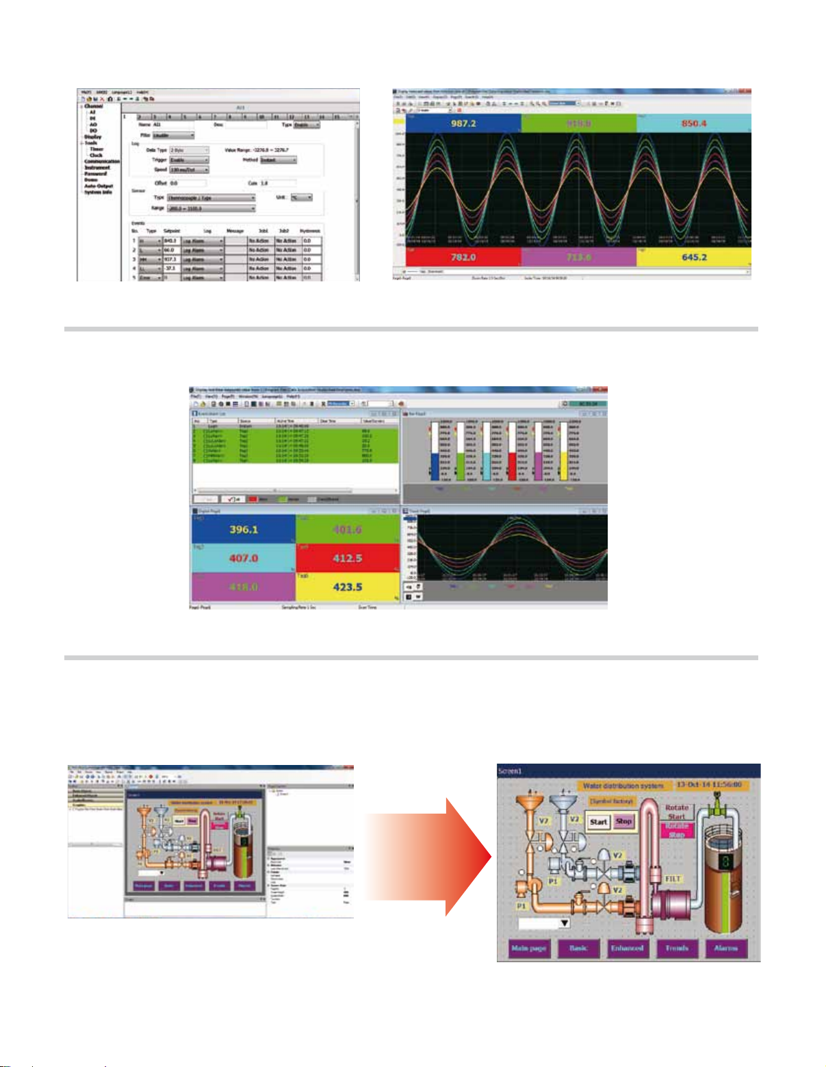
Standard Software (Included)—Consists of Configurator
and Historical Data Viewer
Configuration screen
User can easily configure the recorder on a PC and then
send the configuration files to the recorder.
Displays historical trends, alarms, events and then print it. Use it to
search data by time, time period, tag, alarm, events and remarks.
Data can also be exported in CSV format.
Enhanced Data Acquisition Studio Software (Optional)
Real time viewer
Historical viewer
RD1000-SW Data Acquisition Studio Software (ordered
separately)—adds Real Time Viewer
Panel Studio Software (Included with Plus Version of 2 or 3 of Firmware)
Panel Studio software
Use Panel Studio for easy custom display editing on
a PC, then download to the recorder. The custom
edited displays can be viewed in addition to the
standard displays.
Custom display downloaded to the recorder
7
Page 8
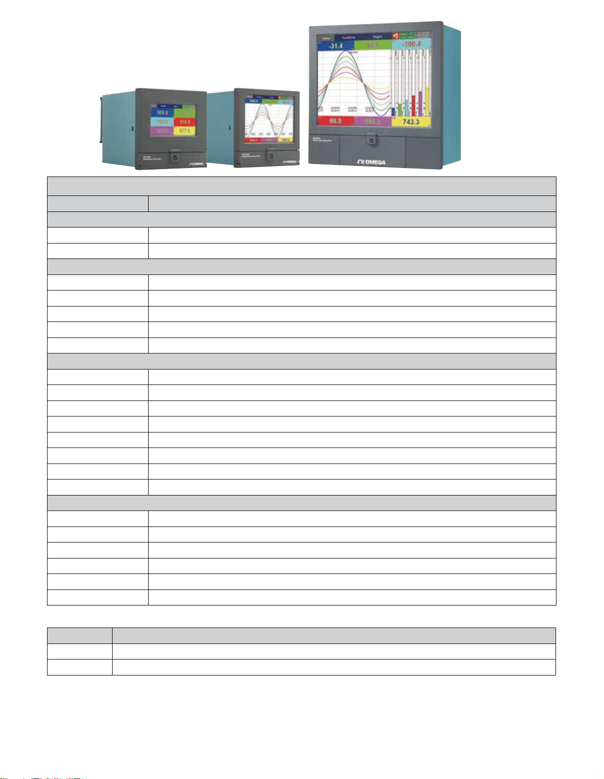
RD2000
RD3000
All models shown
smaller than actual size.
RD1000
To Order
Model No. Description
RD1000 Series Paperless Recorders with 4.3" TFT Display, 4 Slots, up to 6 Analog Inputs
RD1003
RD1006
RD2000 Series Paperless Recorders with 5.6" TFT Display, 4 Slots, up to 24 Analog Inputs
RD2003
RD2006
RD2012
RD2018
RD2024
RD3000 Series Paperless Recorders with 12.1" TFT Display, 16 Slots, up to 48 Analog Inputs
RD3006
RD3012
RD3018
RD3024
RD3030
RD3036
RD3042
RD3048
Options (Field Installable in Spare I/O Slots, One Slot Required for Each Module)
RD1000-3AI
RD1000-6AI
RD1000-6DI
RD1000-6R
RD1000-3R-3DI
RD1000-6AO
Recorder, 3-input, 3 spare I/O slots (includes one RD1000-3AI card)
Recorder, 6-input, 3 spare I/O slots (includes one RD1000-6AI card)
Recorder, 3-input, 3 spare I/O slots (includes one RD1000-3AI card)
Recorder, 6-input, 3 spare I/O slots (includes one RD1000-6AI card)
Recorder, 12-input, 2 spare I/O slots (includes two RD1000-6AI cards)
Recorder, 18-input, 1 spare I/O slots (includes three RD1000-6AI cards)
Recorder, 24-input, no spare I/O slots (includes four RD1000-6AI card)
Recorder, 6-input, 15 spare I/O slots (includes one RD1000-6AI card)
Recorder, 12-input, 14 spare I/O slots (includes two RD1000-6AI cards)
Recorder, 18-input, 13 spare I/O slots (includes three RD1000-6AI cards)
Recorder, 24-input, 12 spare I/O slots (includes four RD1000-6AI cards)
Recorder, 30-input, 11 spare I/O slots (includes ve RD1000-6AI cards)
Recorder, 36-input, 10 spare I/O slots (includes six RD1000-6AI cards)
Recorder, 42-input, 9 spare I/O slots (includes seven RD1000-6AI cards)
Recorder, 48-input, 8 spare I/O slots (includes eight RD1000-6AI cards)
Analog input card, 3 channel
Analog input card, 6 channel
Digital input card, 6 channel
Relay output card, 6 relays
Relay output/digital input card, 3 relays, 3 inputs
Analog output card, 6 outputs
Accessories
Model No. Description
RD1000-SW
2GB-SD
Comes complete with operator’s manual, panel mounting brackets and standard software.
Notes: Recorder offers Ethernet interface as standard. To include RS232 communications add “-RS232” suffix to model number for an
additional cost. To include RS422/485 communications add “-RS422/485” suffix to model number for an additional cost. Standard power for
recorders is 90 to 250 Vac, 47 to 63 Hz. To order recorder with optional 11 to 36 Vdc power, add suffix “-DC” to model number, no additional
cost.
Ordering Example: RD1006, recorder with 6 inputs, plus RD1000-DI6, digital input card, plus RD1000-SW data acquisition studio software
Data acquisition studio software
Spare 2GB SD card
8
 Loading...