

Page 1
®
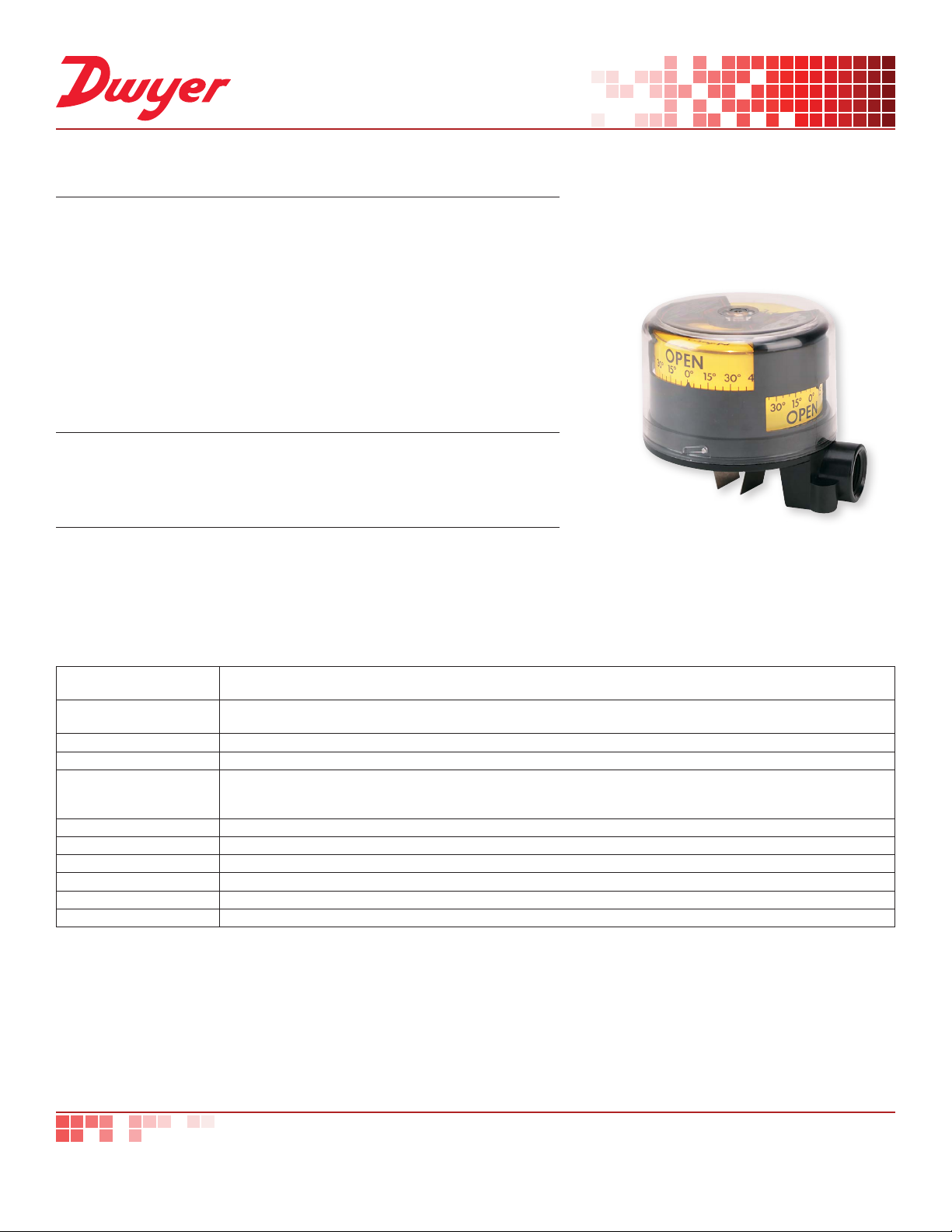
SERIES QV | PROXIMITY QUICK-VIEW® VALVE POSITION INDICATORS/SWITCHES
FEATURES/BENEFITS
• The lowest cost position indication
• Extremely compact design
• Easily interchangeable with key competition
• Backlighting option available for maximum visibility
• Quick-View
stocked for fast delivery
• Flame retardant
• UV protection
• Hazardous location option
APPLICATIONS
• Rotary or linear valve indication
• Industrial damper position monitoring
DESCRIPTION
The Series QV Quick-View® Valve Position Indicators/Switches, now UL and CSA
rated, are produced by Proximity with up to four individual mechanical or proximity
switches. The Quick-View® indicator is also available with optional backlighting.
®
Indicator and mounting kits, including NAMUR kits, are
SPECIFICATIONS
Minimum Rotation Travel
(Switches only)
Maximum Travel
Rotation (Switches only)
Temperature Limits -40 to 180°F (-40 to 82°C).
Switch Type SPDT.
Electrical SPDT Switch
Ratings
Lighting Supply Voltage 24-28 VDC.
Enclosure Material Polycarbonate housing and conduit.
Conduit Entrance One 3/4˝ NPT.
Enclosure Rating NEMA 4, 4X (IP66, IP56). Optional explosion-proof, rated: Class I, Groups A, B, C, D; Class II, Groups F & G; Div. 2.
Maximum Altitude 2000 m (6560 ft).
Agency Approvals CE, CSA, cULus.
5°.
360°.
QV-X1XXXX: 10 A @ 125/250 VAC; 0.5 A 125 VDC; 10 A @ 24 VDC mech. switch; QV-X2XXXX: 1 A @ 125 VAC; 1A @
24 VDC mech. switch; QV-X3XXXX: 2 A @ 125 VAC; 2A @ 30 VDC prox. switch; QV-X4XXXX: 5-25 VDC namur sensor;
QV-X5XXXX: 10-30 VDC inductive sensor; QV-X6XXXX: 10 A @ 125/250 VAC mech. switch.
dwyer-inst.com
DWYER INSTRUMENTS, INC.
T: 219-879-8000 | F: 219-872-9057 | [email protected]
800-872-9141
Page 2
®
CONDUIT ENTRANCE
3 [76.20] CLEARANCE REQUIRED FOR COVER REMOVAL
[77.79]
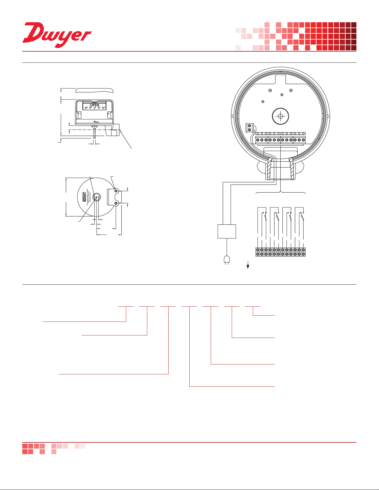
DIMENSIONS
A
A
UPON
REQUEST
LIGHTING OPTION
THE CAMS
4-15/32
[113.5]
5/16
[7.938]
1/2
[12.70]
1/4 DIA. [6.350]
SHAFT LEVER
DRIVE ONLY
3/4 NPT
1/8 DIA. PINS (2)
4-3/4
[120.7]
6-32 UNC
1/4 DP [6.350]
1/4
[6.350]
HOW TO ORDER
Use the bold characters from the chart below to construct a product code.
SERIES
QV: Quick-View® valve position indicator/switch
NUMBER OF SWITCHES
-0: None
-1: One
-2: Two
-3: Three
-4: Four
SWITCH TYPE
0: No switches
1:10A mechanical snap switch
2: 1A mechanical gold contacts
3: 2A Proximity reed switch
4: 5 to 25 VDC namur sensor
5: 10 to 30 VDC inductive sensor
6: 10A mechanical snap switch
1/4
[6.350]
2-3/8
[60.33]
2 MTG HOLES
1/4-20 UNC
7/16 DP [11.11]
1-1/2
[38.10]
24 VDC
-700
VAILABLE
120 VAC
POWER
SUPPLY
3-1/16
QV 01-2 01 1 EX
SW 3
SW 2
SW 1
BOTTOM
SWITCH
RED
RED
NC
NO
CONDUIT
ENTRY
NOTE: SWITCHES SHOWN ACTUATED BY
IN FULLY COUNTERCLOCKWISE POSITION
ABOVE
ABOVE
2ND
1ST
SWITCH
SWITCH
RED
NC
C
WHT
WHT
BLK
BLK
BLK
NC
NO
NO
C
SWITCHING OPTION
ADDITIONAL OPTIONS
EX: Class I, Div. II, Groups A, B, C
& D; Class II, Div. II Groups F & G
VISUAL INDICATION
0: None
1: Standard (open closed)
2: Upside down (open closed)
LIGHTING OPTIONS
0: None
1: 24 to 28 VDC bright white LED’s
ADDITIONAL OPTIONS
01: Direct
02: Lever
03: Namur
WHT
NC
C
SW 4
TOP
SWITCH
BRN
BRN
BRN
NO
C
Important Notice: Dwyer Instruments, Inc. reserves the right to make changes to or discontinue any product or service identied in this publication without notice. Dwyer advises its customers to obtain the
latest version of the relevant information to verify, before placing any orders, that the information being relied upon is current.
DWYER INSTRUMENTS, INC.
T: 219-879-8000 | F: 219-872-9057 | [email protected]
dwyer-inst.com
800-872-9141
DS-QV | 12/18
 Loading...