

Page 1
TM
User’s Guide
Shop online at
omega.com
e-mail: [email protected]
For latest product manuals:
www.omega.com/en-us/pdf-manuals
SST & QST
Split Sheath Insertion Heaters
Page 2
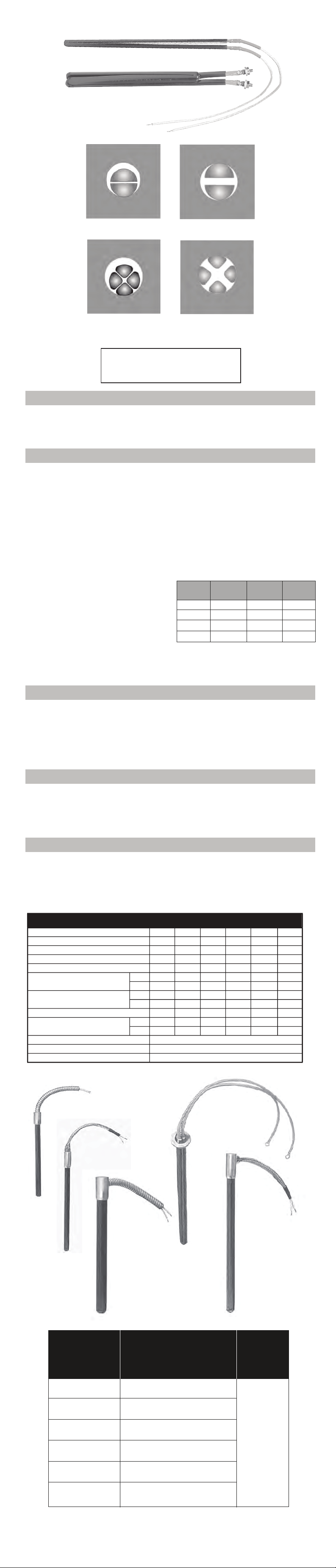
SST Split Sheath Insertion Heater
QST Quad Sheath Insertion Heater
Unenergized SST Energized SST
Unenergized QST Energized QST
NOTICE: Carefully remove heater(s) from
shipping containers and check for shipping
damage. Any damage claims should
be entered immediately with the carrier.
GENERAL
e Chromalox electric cartridge heaters are ruggedly constructed and
if properly installed, operated and maintained, will provide long life and
dependable, trouble-free service.
Since excess temperatures may permanently damage the heaters,
temperature regulating and limiting controls are recommended.
INSTALLATION
WARNING: Hazard of Shock. Disconnect all power before installing
heater.
WARNING: The suitability of these heaters for any particular
application is solely the responsibility of the user. Please check
Chromalox factory or representative for guidance if needed.
If cartridge heater is to be used in platen, dies, mold, etc. the hole
1.
should be drilled and reamed to allow as close a t as is possible.
is is especially important when installing high watt density
heaters. Good surface contact between the heater surface and the
heated metal is essential to good heat transfer and for longer heater
life. A loose t, resulting in poor contact will
cause the heater to “run hot” and could cause premature heater
failure. Table A gives the dierence between nominal and actual
diameters. If further information regarding t or watt density is
required, contact your Chromalox representative or ask for a copy
of Curve G-235 from Chromalox Cartridge
5.
Leadwires must not enter the hole containing the heater. e
lead end of the heater should be ush with the surface of the
part being heated. Make sure that the leads are in an ambient
temperature which does not exceed the maximum temperature
rating of the lead insulation and end seal material.
6.
DANGER: Hazard of Fire. Since cartridge heaters are
capable of developing high temperatures, extreme care should
be taken to:
Avoid mounting heaters in an atmosphere containing
A.
combustible gases and vapors.
B. Avoid contact between heaters and combustible materials.
C. Keep combustible materials far enough away to be free of
the eects of high temperatures.
WARNING: Users should install adequate back-up
controls and safety devices with their electric heating
equipment. Where the consequences of failure may be
severe, back-up controls are essential. Although the
safety of the installation is the responsibility of the user,
Chromalox will assist in identifying equipment options.
WARNING: Never hammer the heater ends when
installing.
2.
Graphite and other lubricants to help insert the cartridge
heater into the hole are not recommended. ey are
electrically conductive and can contaminate the heater and
shorten heater life.
3.
Do not twist or braid wire leads. Where leads are subject to
exing, support the leadwires to prevent them from twisting
or breaking o at the terminal end.
4.
Avoid the use of tape on leads where they emerge from the
cartridge heater. e adhesive on some tapes can
contaminate the heater and shorten heater life.
Nominal Dia.
3/8”
1/2”
5/8”
3/4”
Actual Dia.
+.000
–.005
.373”
.498”
.622”
.747”
5/16”
1”
3/8”
Actual Dia.
+.000
–.005Nominal Dia.
.933
996
.373”
WIRING
WARNING: Hazard of Shock. Any installation involving electric
heaters must be effectively grounded in accordance with the
National Electrical Code to eliminate shock hazard.
Electric wiring to heating elements must be installed in accordance
1.
with National Electrical Codes and Local Electrical Codes
by a qualied person as dened in the NEC.
Use high-temperature manganese nickel leadwire or alloy busbar
2.
for electrical connections at the heater itself. Insulated copper
leadwire may be used up to 350°F.
OPERATION
Do not operate heaters at voltages in excess of that stamped on
1.
the heater since excess voltage will shorten heater life.
Do not operate heaters under conditions that result in temperatures
2.
higher than the recommended maximum since excess
temperatures can cause premature heater failure.
e maximum recommended temperature on sheath materials
normally supplied is:
MAINTENANCE
WARNING: Hazard of Shock. Disconnect all power
to heaters before servicing or replacing heaters.
Make certain that the terminals or leads and heater sheath are
1.
free from contact with oil, liquids or other foreign matter.
Note: Chromalox cannot be responsible for failures or damage
caused by organic contamination in cartridge heaters. Make certain
that the heaters are not exposed to organic contaminants.
Tolerances and Limitations
SST
QST
SST
QST
SST
QST
3/8”
.370”
5”
60”
N/A
.278
11
240
15
Nominal Sheath Diameter
Actual Sheath Diameter (±.003)
Minimum Sheath Length
Maximum Sheath Length – SST
Maximum Sheath Length – QST
Minimum Ohms/inch of EHL*
Maximum Ohms/inch of EHL*
Maximum Standard Voltage
Maximum Amperage
Wattage
Resistance
Sheath Length
3.
Cartridge heaters of 5/8” diameter and larger and of equal
wattage and voltage can be series-connected across 480
volts maximum power supply. Smaller diameter units of
equal rating can be series-connected across 250 volts
maximum. An extra layer of high temperature Fiberglass
sleeving is recommended for the leadwire to increase
electrical insulation.
4.
Protection with properly sized fuses/breakers is required to
minimize hazards.
3.
Electrical terminals should be protected from spillage of
plastics, water, oil, and their vapors which can create
electrical hazards and/or heater failure.
2.
Check electrical connections and tighten if necessary. is
will help avoid hot terminals that may destroy wire
insulation or heater terminals.
3.
Check overheat operation to insure heater protection.
4.
REPAIR — For In-Warranty repair please follow
instructions
1/2”
5/8”
495”
.620”
5”
5”
60”
60”
36”
36” 36”
.308
-
.593
-
-
21
38
240
30
30
.296 .296
.593 .593
21
38
240
40
30
+5% – 10%
+10% – 5%
±3% up to 20”, ±2% over 20”
WARRANTY
Stainless Steel — 1200°F
Alloy
11/16”
.682”
5”
60”
— 1600°F
3/4”
.745”
5”
60”
36”
.350
.593
26
21
38
38
40
30
480
40
30
480
1”
.995”
5”
60”
N/A
.350
-
26
-
480
40
-
Fig. 04C
Fig. 10C
Fig. 13C
Fig. 17C
Fig. 15C
SST or QST*
Diameter
3/8”
1/2”
5/8”
11/16”
3/4”
1”
04C, 15C, 13C & 17C
Figures
5/8” x 1-1/2”
5/8” x 1-1/2”
3/4” x 1-1/2”
3/4” x 1-1/2”
7/8” x 1-1/2”
1-1/8” x 1-1/2”
* QST (QUAD) N/A in 3/8” Diameter
** Not applicable to Fig. 13C or Fig. 17C
Cable
O.D.*
15/32
Page 3

WARRANTY /DISCLAIMER
OMEGA ENGINEERING, INC. warrants this unit to be free of defects in materials and
workmanship for a period of 13 months from date of purchase. OMEGA’s WARRANTY adds
an additional one (1) month grace period to the normal one (1) year product warranty to
cover handling and shipping time. This ensures that OMEGA’s customers receive maximum
coverage on each product.
If the unit malfunctions, it must be returned to the factory for evaluation. OMEGA’s Customer
Service Department will issue an Authorized Return (AR) number immediately upon phone
or written request. Upon examination by OMEGA, if the unit is found to be defective, it
will be repaired or replaced at no charge. OMEGA’s WARRANTY does not apply to defects
resulting from any action of the purchaser, including but not limited to mishandling, improper
interfacing, operation outside of design limits, improper repair, or unauthorized modication.
This WARRANTY is VOID if the unit shows evidence of having been tampered with or shows
evidence of having been damaged as a result of excessive corrosion; or current, heat, moisture
or vibration; improper specication; misapplication; misuse or other operating conditions
outside of OMEGA’s control. Components in which wear is not warranted, include but are not
limited to contact points, fuses, and triacs.
OMEGA is pleased to oer suggestions on the use of its various products. However,
OMEGA neither assumes r esponsibility for any omissions or e rrors nor assumes
liability for any damages that result from the use of its products in accordance
with information provided by OMEGA, either verbal or written. OMEGA warrants
only that the parts manufactured by the company will be as specied and free of
defects. OMEGA MAKES NO OTHER WARRANTIES OR REPRESENTATIONS OF ANY
KIND WHATSOEVER, EXPRESSED OR IMPLIED, EXCEPT THAT OF TITLE, AND ALL
IMPLIED WARRANTIES INCLUDING ANY WARRANTY OF MERCHANTABILITY AND
FITNESS FOR A PARTICULAR PURPOSE ARE HEREBY DISCLAIMED. LIMITATION
OF LIABILITY: The remedies of purchaser set forth herein are exclusive, and the
total liability of OMEGA with respect to this order, whether based on contract,
warranty, negligence, indemnication, strict liability or otherwise, shall not exceed
the purchase price of the component upon which liability is based. In no event shall
OMEGA be liable for consequential, incidental or special damages.
CONDITIONS: Equipment sold by OMEGA is not intended to be used, nor shall it be used: (1)
as a “Basic Component” under 10 CFR 21 (NRC), used in or with any nuclear installation or
activity; or (2) in medical applications or used on humans. Should
with any nuclear installation or activity, medical application, used on humans, or misused in
any way, OMEGA assumes no responsibility as set forth in our basic WARRANT Y / DISCLAIMER
language, and, additionally, purchaser will indemnify OMEGA and hold OMEGA harmless from
any liability or damage whatsoever arising out of the use of the Product(s) in such a manner.
any Product(s) be used in or
Direct all warranty and repair requests/inquiries to the OMEGA Customer Service Department.
RETURN REQUESTS/INQUIRIES
BEFORE RETURNING A NY PRODUCT(S) TO OMEGA, P URCHASER MUST OBTAIN AN
AUTHORIZED RETURN (AR) NUMBER FROM OMEGA’S CUSTOMER SERVICE DEPARTMENT
(IN ORDER TO AVOID PROCESSING DELAYS). The assigned AR number should then be
marked on the outside of the return package and on any correspondence.
The purchaser is responsible for shipping charges, freight, insurance and proper packaging to
prevent breakage in transit.
FOR WARRANT Y RETURNS, please have
the following information available BEFORE
contacting OMEGA:
1. Purchase Order number under which
the product was PURCHASED,
2. Model and serial number of the product
under warranty, and
3. Repair instructions and/or specic
problems relative to the product.
O MEGA’s policy is to make running changes, not model changes, whenever an improvement is possible.
This aords our customers the latest in technology and engineering.
OMEGA is a trademark of OMEGA ENGINEERING, INC.
© Copyright 2019 OMEGA ENGINEERING, INC. All rights reserved. This document may not be copied, photocopied,
reproduced, translated, or reduced to any electronic medium or machine-readable form, in whole or in part, without
the prior written consent of OMEGA ENGINEERING, INC.
FOR NON-WARRANTY REPAIRS,
consult
OMEGA for current repair charges. Have the
following information available BEFORE
contacting OMEGA:
1. Purchase Order number to cover the
COST of the repair,
2. Model and serial number of the product, and
3. Repair instructions and/or specic problems
relative to the product.
Page 4

omega.com [email protected]
Servicing North America:
U.S.A.
Headquarters:
Omega Engineering, Inc.
Toll-Free: 1-800-826-6342 (USA & Canada only) Customer
Service: 1-S00-622-2378 (USA & Canada only)
Engineering Service: 1-800-872-9436 (USA & Canada only)
Tel: (203) 359-1660 Fax: (203) 359-7700
e-mail: [email protected]
For Other Locations Visit omega.com/worldwide
 Loading...