

Page 1
User’s Guide
Shop online at
omega.com
e-mail: [email protected]
For latest product manuals:
www.omegamanual.info
®
PX709 SERIES
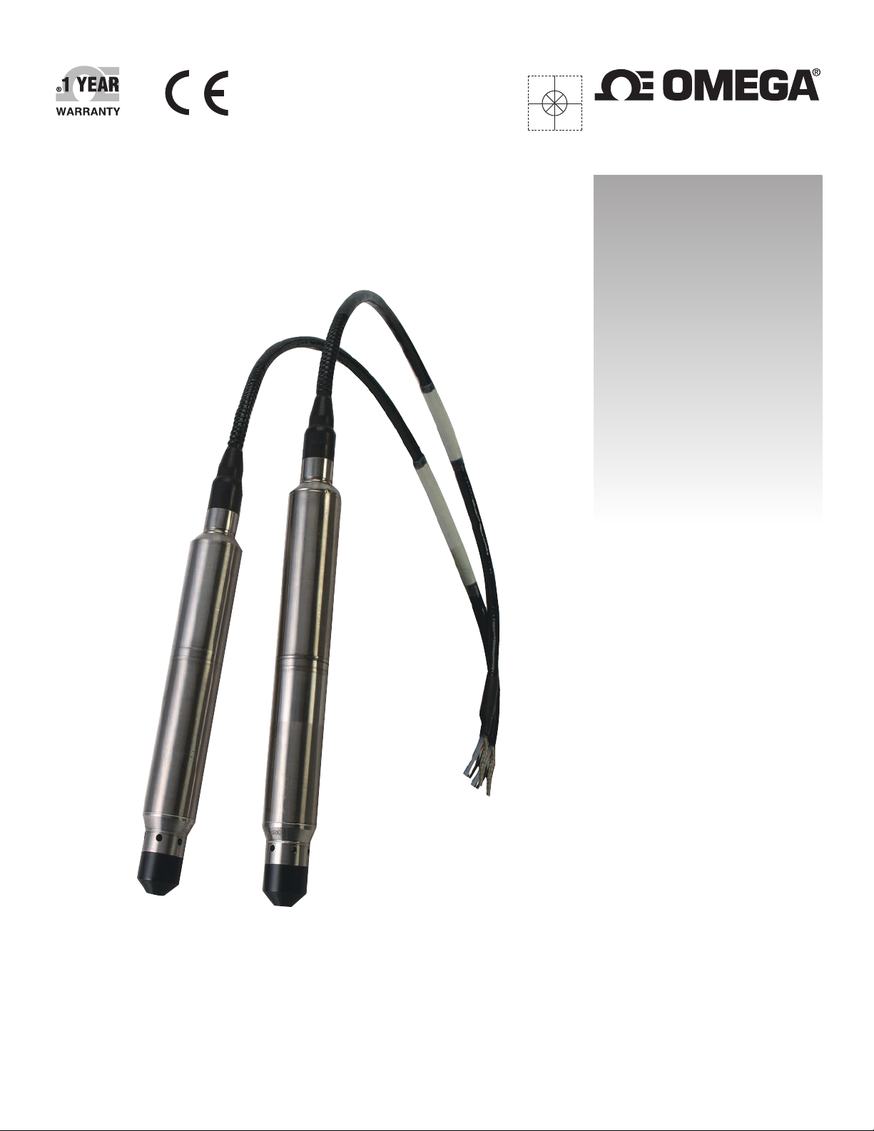
Submersible
Pressure Transducers
Page 2

omega.com [email protected]
Servicing North America:
U.S.A.: Omega Engineering, Inc., One Omega Drive, P.O. Box 4047
Stamford, CT 06907-0047 USA
Toll-Free: 1-800-826-6342 (USA & Canada only)
Customer Service: 1-800-622-2378 (USA & Canada only)
Engineering Service: 1-800-872-9436 (USA & Canada only)
Tel: (203) 359-1660 Fax: (203) 359-7700
e-mail: [email protected]
For Other Locations Visit omega.com/worldwide
The information contained in this document is believed to be correct, but OMEGA accepts no liability for any errors it contains, and reserves
the right to alter specifications without notice.
WARNING: These products are not designed for use in, and should not be used for, human applications.
Page 3

PX709 SERIES Submersible Pressure Transducer
Table of Contents
Section Page
Section 1 Overview ....................................................................................... 1-1
Section 2 Features ......................................................................................... 2-1
Section 3 General Maintenance ................................................................. 3-1
Section 4 Voltage Output ............................................................................ 4-1
4.1 Specications ................................................................................ 4-1
4.2 Wiring .............................................................................................4-1
Section 5 Current Output ............................................................................ 5-1
5.1 Specications ................................................................................ 5-1
5.2 Wiring ............................................................................................ 5-1
Section 6 Millivolt/Volt Output ................................................................. 6-1
6.1 Specications ................................................................................ 6-1
6.2 Wiring ............................................................................................ 6-1
Section 7 Termination Enclosure ............................................................... 7-1
i
Page 4

PX709 SERIES Submersible Pressure Transducer
List of Figures
Section Figure Description ................................ Page
Section 4
Section 5
Section 6
Section 7
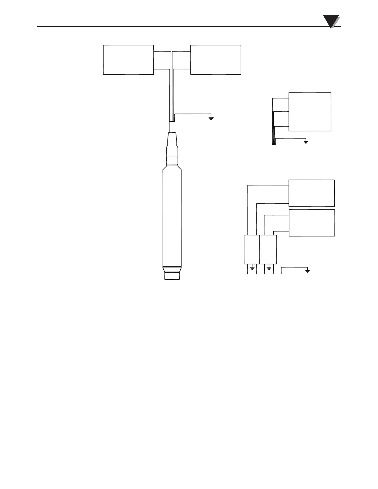
4-1 Voltage Wiring Diagram ....................................... 4-1
5-1 Current Wiring Diagram ...................................... 5-1
6-1 Millivolt/Volt Wiring Diagram ........................... 6-1
7-1 Termination Enclosure
Without Surge Protection ..................................... 7-2
7-2 Termination Enclosure
With Surge Protection ........................................... 7-2
ii
Page 5

Section 1 - Overview
Unless otherwise noted, this manual contains user information for the following sensors
provided by Omega Engineering Inc:
PX709 and PXM709 Series Submersible Pressure Transducers.
Overview
1
1-1
Page 6
2
Features
Section - 2 Features
3 Pressure Types: Gage pressure (vented through the cable), Sealed gage
pressure, Absolute pressure
4 Outputs: mV/V, 0-5Vdc, 0-10Vdc, or 4-20 mA
Pressure Ranges: from 10 inH2O to 1000 psi
The Standard cable length is 10 ft and optional lengths are available up to 300 ft.
NPTPipeconduittting:NPTmaletting,allowsrigidmountingtotheconduit,
see PX709C
Optional Lightning Protection: Integral lightning surge protection to IEC-610004-5 (Level 4).
DryingTubeAssembly:Cleartubelledwithindicatingdesiccant,attaches
directly to cable vent tube and intercepts water vapor. We highly recommended
the desiccant tube when operating in high humidity conditions. Must be
periodically renewed as desiccant becomes saturated, turning color from blue
(dry) to pink (saturated).
NOTE:
Drying tubes are not required for sealed gage or absolute pressure
models (Vent tube is sealed at sensor).
Termination Enclosure: Convenient option complementing gage-type pressure/
level transmitters, where it is desired to terminate the transmitter cable close to
the measurement point. It includes a NEMA 4X clear front enclosure (9.9 x 5.8
x3.0")withtwo,liquid-tightcablettings(onein,oneout),aterminalstripor
surge protection, and ample room for mounting a drying tube, and a waterproof
vent. See page 7-1 for more detail.
External Surge Protector - Surge protection is recommended on sensors with
very long cable for lightning/surge protection of user's power supply/readout.
2-1
Page 7
Section 3 - General Maintenance
Under no circumstances should the pressure input port to the PX709
be probed with any object. Damage to the sensing diaphragm can be
permanent and in most cases requires repair or replacement.
Transmitter Anchoring:
It is recommended that PX709 submersible transmitters be installed in a
stilling well or attached to rigid conduit using the PX709C with the integral
conduitttinginordertopreventdamagetothetransmitterfromimpactwith
immovable objects. It is not advisable to tie the transmitter to a pump or to
piping, as any problem with the transmitter could require that the pump be
pulled from the installation.
Some applications require the transmitter to be suspended without a protective
stilling well or conduit attachment. In all installations, care should be taken to
prevent damage to the submersible cable.
General Maintenance
WARNING:
3
Transmitter Submersion:
Damage to submersible cable can lead to failure of the transmitter. Omega
employs a cable made with a Polyurethane jacket with double Kevlar reinforcing
stringers, fused to case, with large vent tube to minimize the risk of cuts and
abrasion. Still, take care when lowering your transmitter into the well, making
sure the cable does not drag over sharp edges. Avoid dropping the transmitter
from the surface.
Condensation protection:
Omegadyne has optimized the size of the cable vent to minimize the occurrence
of water vapor incursion. In areas of high humidity, it may be desirable to use
a Drying Tube Assembly (desiccant) to prevent water vapor from entering the
vent tube. An enclosure with a desiccant is available as an option. See page 7-1
for details and options.
Bending of Cable:
OurPolyurethanejacketedcableisquiteexible.Howevercaremustbetakento
ensure the vent tube integral to the cable is not crimped when bending the cable
to suit your installation. It is recommended that the cable not be bent to a radius
smaller than 2 inch.
Cable Compression:
Manyusersemployacompressionttingtosecureourcableasitentersa
junctionbox.Caremustbetakenthatthettingisnotovertightened,causing
damage to the cable and/or crimping the vent tube.
Position Sensitivity:
The transmitter should be installed in a vertical position; otherwise it may
exhibit an offset. If the transmitter must be installed in any position other than
vertical, measure the output with no pressure applied prior to connection to
your display, PLC, or controller. Use the measured value for your zero point.
3-1
Page 8

4
Voltage Output
Section 4 – Voltage Output
4.1 Specifications
Output: 0 to 5, 0 to 10 Vdc
Operating Current: Less than 10 mA
Supply Voltage Range: 10 to 30 Vdc (0 to 5 Volt Output)
Supply Voltage Range: 16 to 30 Vdc (0 to 10 Volt Output
Response Time: 1 mSec
Output Common Mode: 0 volts (Output can be used as 3-wire with
Reverse Voltage Protection:
Do not short + output to the + supply. Permanent damage will occur.
reduced accuracy)
A four wire connection is recommended for long
cables and sensors with lightning protection due
to voltage drop in the cable.
Yes
CAUTION:
4.2. Wiring
Red: +Excitation
Black: -Excitation
White: +Output Signal
Green: -Output Signal
3-1
Page 9
VOLT METER
+SIGNAL
-SIGNAL
WHITE
GREEN
RED
BLACK
+EXCITATION
-EXCITATION
POWER
SUPPLY
Voltage Output
THREE WIRE CONNECTION
WHITE
+SIGNAL
4
DRAIN WIRE
RED
+EXCITATION
BLACK
-EXCITATION/-SIGNAL
GREEN
DRAIN WIRE
POWER
SUPPLY
WIRING WITH SURGE PROTECTION
GREEN
-SIGNAL
VOLT
WHITE
+SIGNAL
RED
+EXCITATION
BLACK
-EXCITATION
(2) 2-CH SURGE PROTECTION
FOR USER'S EQUIPMENT
METER
POWER
SUPPLY
DRAIN WIRE
Figure 4-1 Voltage Wiring Diagram
4-1
Page 10
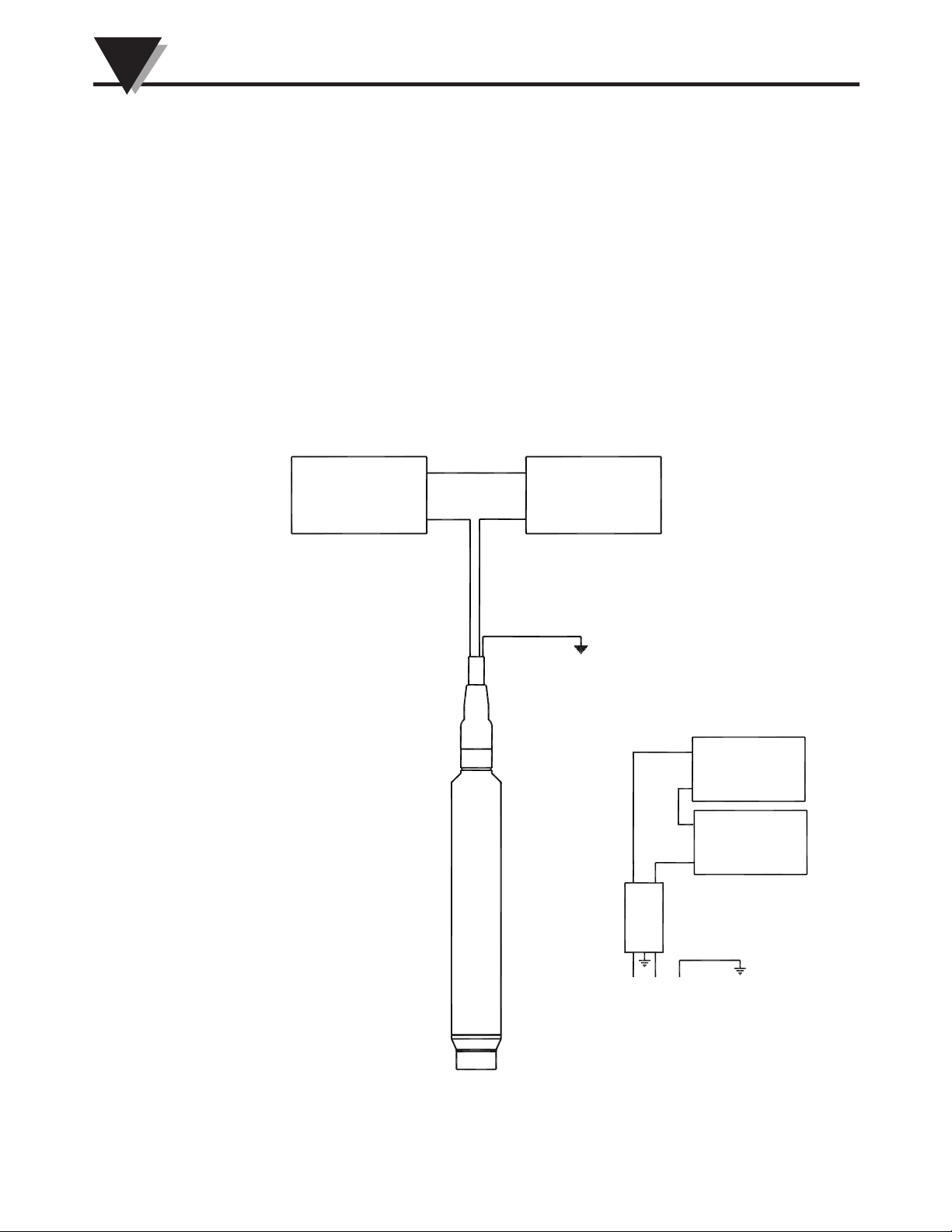
5
CURRENT
METER
POWER
SUPPLY
-EXCITATION
+EXCITATION
RED
BLACK
-SIGNAL
+SIGNAL
DRAIN WIRE
CURRENT
METER
POWER
SUPPLY
-EXCITATION
+EXCITATION
RED
BLACK
-SIGNAL
+SIGNAL
DRAIN WIRE
2-CH SURGE PROTECTION
FOR USER'S EQUIPMENT
WIRING WITH SURGE PROTECTION
Current Output
Section 5 - Current Output
5.1 Specifications
Output: 20 mA
Operating Current: 28 mA max
Supply Voltage Range: 10 to 30 volts
Response Time: 1 mSec
Reverse Voltage Protection: Yes
Max Loop Resistance: (Input supply voltage -10) x 50 ohms
5.2 Wiring
Red: +Input
Black: -Input
5-1
Figure 5-1 Current Wiring Diagram
Page 11
Section 6 - Millivolt/Volt Output
6.1 Specifications
Output: 30 mV @ 10 Vdc (15 mV @ 5 volts)
Output Resistance: 5000 ohms
Operating Current: Less than 6mA
Supply Voltage Range: 5 to 10 volts (5 volt minimum - 10.6 maximum)
Response Time: 1 mSec
Output Common Mode: 1/2 of supply voltage
Electronically linearized; do not reverse excitation polarity.
6.2 Wiring
Red: +Excitation
Black: -Excitation
White: +Output Signal
Green: -Output Signal
Millivolt/Volt Output
6
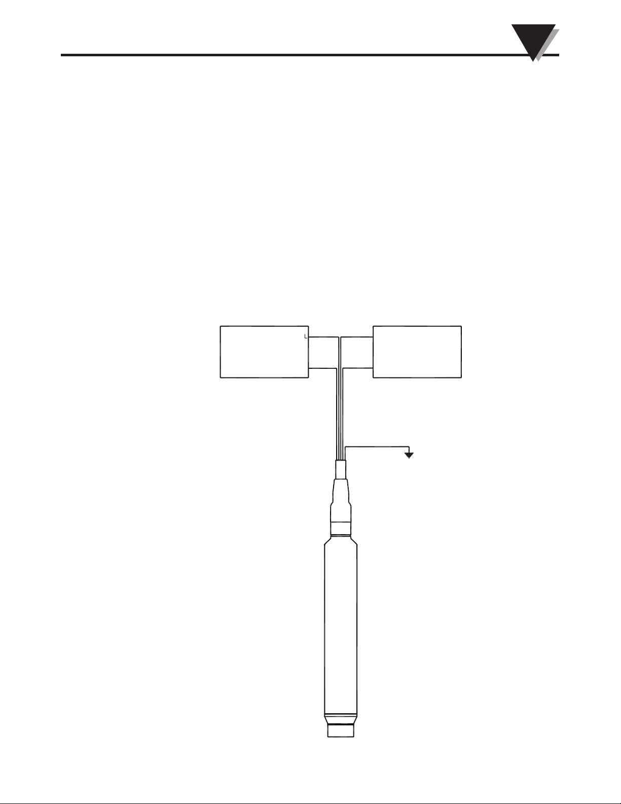
VOLT METER
+SIGNA
-SIGNAL
WHITE
GREEN
RED
BLACK
+EXCITATION
-EXCITATION
DRAIN WIRE
POWER
SUPPLY
Figure 6-1 Millivolt/Volt Wiring Diagram
6-1
Page 12

7
Termination Enclosure
Section 7 - Termination Enclosure
Desiccant Tube:
Alwaysinstalladesiccantventlterimmediatelyaftergagetransducer
installation. Failure to use one could result in premature failure of the
transducer; which would not be covered by warranty. If you use a desiccant
lter,youshouldestablisharegularmaintenanceschedule.Youshouldchange
yourventlterwhenitis75%spent(pinkcolor).Replacementlters(part
number A019385) are available at a nominal cost from the Omega Engineering.
Donotremovetheoldventlteruntilanewoneisavailable.Themostcommon
failure mode of our transducers is moisture and corrosion damage due to lack of
useormaintenanceoftheventlter.Thiswillallowairintothedesiccantlter
and allows the transducer to properly vent with changes in barometric pressure.
Drain Wire:
The drain wire should be tied to a good earth ground with a minimum of a #22
AWG wire or heavier.
Surge Protection at the Termination Enclosure:
For long cable runs in areas that are prone to lightning a surge protector is
recommend at the end of the cable to protect the user’s equipment from damage.
A Bourns 1820 - 28-A3 is recommended for both the current and voltage versions
of the PX709LGW. The termination enclosure can be ordered with terminals or
surge protectors and a desiccant tube.
PX709-BOX1- Waterproof enclosure with no surge protection.
PX709-BOX2- Waterproof enclosure with surge protection for mA Output
models.
PX709-BOX3- Waterproof enclosure with surge protection for 5V/10V Output
models
7-1
Page 13
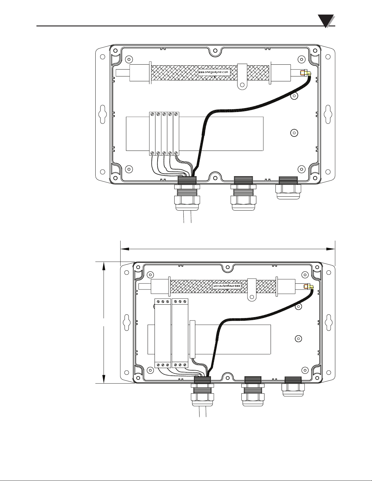
DESICCANT DRYING TUBE OMEGA P/N A019385
Termination Enclosure
7
5.802
EARTH GROUND
PX709GW
DIN RAIL
TO INSTRUMENTATION
Figure 7-1 Termination Enclosure Without Surge Protection
9.921
DESICCANT DRYING TUBE OMEGA P/N A019385
VENT
SURGE
PROTECTION
OR TERMINALS
SURGE
PROTECTION
OR TERMINALS
EARTH GROUND
PX709GW
DIN RAIL
TO INSTRUMENTATION
Figure 7-2 Termination Enclosure With Surge Protection
VENT
7-2
Page 14

PX709 SERIES Submersible Pressure Transducer
NOTES:
7-3
Page 15

WARRANTY/DISCLAIMER
OMEGA ENGINEERING, INC. warrants this unit to be free of defects in materials and workmanship for a
period of 13 months from date of purchase. OMEGA’s WARRANTY adds an additional one (1) month
grace period to the normal one (1) year product warranty to cover handling and shipping time. This
ensures that OMEGA’s customers receive maximum coverage on each product.
If the unit malfunctions, it must be returned to the factory for evaluation. OMEGA’s Customer Service
Department will issue an Authorized Return (AR) number immediately upon phone or written request.
Upon examination by OMEGA, if the unit is found to be defective, it will be repaired or replaced at no
charge. OMEGA’s WARRANTY does not apply to defects resulting from any action of the purchaser,
including but not limited to mishandling, improper interfacing, operation outside of design limits,
improper repair, or unauthorized modification. This WARRANTY is VOID if the unit shows evidence of
having been tampered with or shows evidence of having been damaged as a result of excessive corrosion;
or current, heat, moisture or vibration; improper specification; misapplication; misuse or other operating
conditions outside of OMEGA’s control. Components in which wear is not warranted, include but are not
limited to contact points, fuses, and triacs.
OMEGA is pleased to offer suggestions on the use of its various products. However,
OMEGA neither assumes responsibility for any omissions or errors nor assumes liability for
any damages that result from the use of its products in accordance with information provided
by OMEGA, either verbal or written. OMEGA warrants only that the parts manufactured by the
company will be as specified and free of defects. OMEGA MAKES NO OTHER WARRANTIES OR
REPRESENTATIONS OF ANY KIND WHATSOEVER, EXPRESSED OR IMPLIED, EXCEPT THAT OF
TITLE, AND ALL IMPLIED WARRANTIES INCLUDING ANY WARRANTY OF MERCHANTABILITY
AND FITNESS FOR A PARTICULAR PURPOSE ARE HEREBY DISCLAIMED. LIMITATION OF
LIABILITY: The remedies of purchaser set forth herein are exclusive, and the total liability of
OMEGA with respect to this order, whether based on contract, warranty, negligence,
indemnification, strict liability or otherwise, shall not exceed the purchase price of the
component upon which liability is based. In no event shall OMEGA be liable for
consequential, incidental or special damages.
CONDITIONS: Equipment sold by OMEGA is not intended to be used, nor shall it be used: (1) as a “Basic
Component” under 10 CFR 21 (NRC), used in or with any nuclear installation or activity; or (2) in medical
applications or used on humans. Should any Product(s) be used in or with any nuclear installation or
activity, medical application, used on humans, or misused in any way, OMEGA assumes no responsibility
as set forth in our basic WARRANTY/D ISCLAIMER language, and, additionally, purchaser will indemnify
OMEGA and hold OMEGA harmless from any liability or damage whatsoever arising out of the use of the
Product(s) in such a manner.
RETURN REQUESTS/INQUIRIES
Direct all warranty and repair requests/inquiries to the OMEGA Customer Service Department.
BEFORE RETURNING ANY PRODUCT(S) TO OMEGA, PURCHASER MUST OBTAIN AN AUTHORIZED
RETURN (AR) NUMBER FROM OMEGA’S CUSTOMER SERVICE DEPARTMENT (IN ORDER TO AVOID
PROCESSING DELAYS). The assigned AR number should then be marked on the outside of the return
package and on any correspondence.
The purchaser is responsible for shipping charges, freight, insurance and proper packaging to prevent
breakage in transit.
FOR WARRANTY RETURNS, please have the
following information available BEFORE
contacting OMEGA:
1. Purchase Order number under which the product
was PURCHASED,
2. Model and serial number of the product under
warranty, and
3. Repair instructions and/or specific problems
relative to the product.
OMEGA’s policy is to make running changes, not model changes, whenever an improvement is possible. This affords
our customers the latest in technology and engineering.
OMEGA is a registered trademark of OMEGA ENGINEERING, INC.
© Copyright 2013 OMEGA ENGINEERING, INC. All rights reserved. This document may not be copied, photocopied,
reproduced, translated, or reduced to any electronic medium or machine-readable form, in whole or in part, without the
prior written consent of OMEGA ENGINEERING, INC.
FOR NON-WARRANTY REPAIRS,
for current repair charges. Have the following
information available BEFORE contacting OMEGA:
1. Purchase Order number to cover the COST
of the repair,
2. Model and serial number of the product, and
3. Repair instructions and/or specific problems
relative to the product.
consult OMEGA
Page 16

Where Do I Find Everything I Need for
Process Measurement and Control?
OMEGA…Of Course!
Shop online at omega.com
TEMPERATURE
MU
Thermocouple, RTD & Thermistor Probes, Connectors, Panels & Assemblies
MU
Wire: Thermocouple, RTD & Thermistor
MU
Calibrators & Ice Point References
MU
Recorders, Controllers & Process Monitors
MU
Infrared Pyrometers
PRESSURE, STRAIN AND FORCE
MU
Transducers & Strain Gages
MU
Load Cells & Pressure Gages
MU
Displacement Transducers
MU
Instrumentation & Accessories
FLOW/LEVEL
MU
Rotameters, Gas Mass Flowmeters & Flow Computers
MU
Air Velocity Indicators
MU
Turbine/Paddlewheel Systems
MU
Totalizers & Batch Controllers
SM
pH/CONDUCTIVITY
MU
pH Electrodes, Testers & Accessories
MU
Benchtop/Laboratory Meters
MU
Controllers, Calibrators, Simulators & Pumps
MU
Industrial pH & Conductivity Equipment
DATA ACQUISITION
MU
Data Acquisition & Engineering Software
MU
Communications-Based Acquisition Systems
MU
Plug-in Cards for Apple, IBM & Compatibles
MU
Data Logging Systems
MU
Recorders, Printers & Plotters
HEATERS
MU
Heating Cable
MU
Cartridge & Strip Heaters
MU
Immersion & Band Heaters
MU
Flexible Heaters
MU
Laboratory Heaters
ENVIRONMENTAL
MONITORING AND CONTROL
MU
Metering & Control Instrumentation
MU
Refractometers
MU
Pumps & Tubing
MU
Air, Soil & Water Monitors
MU
Industrial Water & Wastewater Treatment
MU
pH, Conductivity & Dissolved Oxygen Instruments
M5358/1013
 Loading...