

Page 1
Quick Start Function Summary
NORWALK, CT
Instructions for OMEGA® PX5200
Differential Pressure Transmitter
User’s Guide
Shop online at
omega.com
e-mail: [email protected]
For latest product manuals:
www.omegamanual.info
SM
PX5200
M5091/0817
Page 2
2
Omega PX5200 I&M011 10192 (GC52) QS Rev. B _layout 5/18/12 2:48 PM Page 2
Page 3

omega.com [email protected]
Servicing North America:
U.S.A. Omega Engineering, Inc.
Headquarters: Toll-Free: 1-800-826-6342 (USA & Canada only)
Customer Service: 1-800-622-2378 (USA & Canada only)
Engineering Service: 1-800-872-9436 (USA & Canada only)
Tel: (203) 359-1660 Fax: (203) 359-7700
e-mail: [email protected]
For Other Locations Visit omega.com/worldwide
The information contained in this document is believed to be correct, but OMEGA accepts no liability for any errors it contains,
and reserves the right to alter specifications without notice.
Page 4
4
Omega PX5200 I&M011 10192 (GC52) QS Rev. B _layout 5/18/12 2:48 PM Page 4
Page 5
5
MOUNTING
General
The PX5200 was designed to be mounted using the bracket supplied. Pressure connections via the (2)
1
⁄4 NPT female pressure ports. Although the display can be rotated in 90
degree increments by removing the display cover it is preferable to orientate the electrical
termination downward, particularly in applications where protection from the environment
is required.
Mounting Orientation
It is preferable to orientate the unit with the pressure ports either downward or upward.
If mounting with pressure ports to the side an “orientation effect” will be seen at zero
pressure as the pressure generated by the silicone oil fill will appear as a zero offset. If
mounting in this manner this effect may be taken out by re-setting zero in final mounting
orientation.
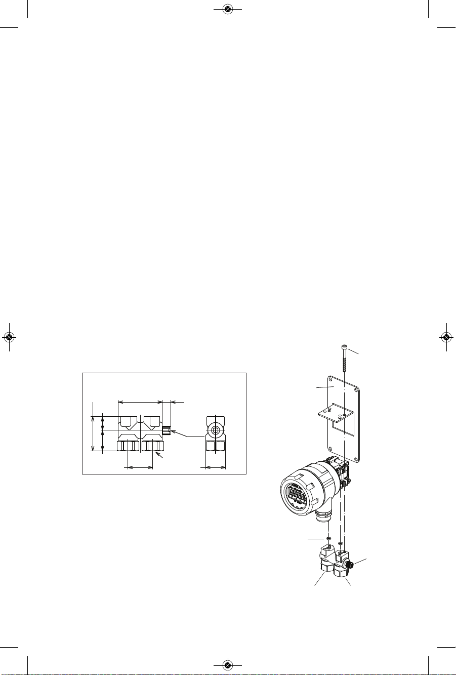
Installing Pressure Port Manifold
(1) Mounting 25.4mm Manifold (
1
⁄4˝ NPT female ports)
Manifold is secured using the (4) socket head bolts (M4x40) and appropriate allen
wrench which is supplied. Check for dust and dirt on the O-ring and seal area,
clean if necessary, before installing to ensure proper connection. The direction of
the manifold is not important, determine best position by ability to operate the
equalizing valve.The equalizing valve is used to open both ports to the line pressure at time of installation. Once installed and the system has been pressurized the
valve needs to be closed to isolate the low and high pressure sides of the device.
Tighten the equalizing valve with a torque of 0.75 ft-lbs±15%. When loosening
the valve do not back off by more than three turns from the closed position.
(2) Panel Mounting
Similar to (1) above except that the PX5200 is put between the manifold and the
bracket and then the (4) socket head bolts (M4x40) are installed.
(2) 1/4˝ NPTF
1.4 (35)
.55 (14)
.83 (21)
1.8 (45.4)
1.0 (25.4)
Hex .83 (21)
.33 (8.5)
Equalizing
valve
Low pressure
inlet (L)
Panel mounting
bracket
High pressure
inlet (H)
Equalizing
valve
M4 x 40
O-rings
Lower connection diagram
Connection: Lower side.
• 1.0 in. (25.4mm) mounting manifold
Omega PX5200 I&M011 10192 (GC52) QS Rev. B _layout 5/18/12 2:48 PM Page 5
Page 6
6
PIPING
Note: High (H) and Low (L) pressure sides of the device are marked on the yellow label
affixed to the housing of the unit.
Install the high pressure side of the applied differential pressure in the pressure inlet of
the high pressure side (H) and the low pressure side in the pressure inlet of the low
pressure side (L).
(Refer to the outline drawing of section 14.)
After the piping is completed check for leaks.
(1) Piping of 1.0 in (25.4mm) Manifold (
1
⁄4˝ npt female ports)
Use caution when installing to keep metal chips and other debris from entering
pressure transmitter. In addition, when sealing tape is used, do not apply to last two
threads at the end of the fitting
Note:
• When transporting and / or mounting do not apply excessive shock or use device
as a step.
• The piping should be of proper length so as not to apply load to the connection
point on the transmitter.
• At the time of mounting or when bleeding air from the device be sure to open the
equalizing valve with a flathead screwdriver so that excessive pressure (more than
the allowable maximum differential pressure) is not applied to the differential pressure sensor. Maximum torque to apply to equalizer valve is 0.75 ft-lbs ±5%.
Omega PX5200 I&M011 10192 (GC52) QS Rev. B _layout 5/18/12 2:48 PM Page 6
Page 7
7
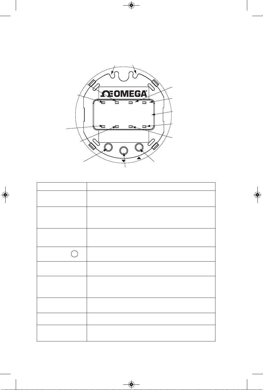
DISPLAY OVERVIEW
DESIGNATION FUNCTION
Measured data
display
Differential pressure, linear scaling value are displayed.
Differential
pressure unit
monitor
When this unit monitor is ON, the differential pressure
(in H
2
O) is indicated on the measured data display.
Scaling; arbitrary
unit monitor
When this unit monitor is ON, the scaling value of an
arbitrary unit (linear scaling), is indicated on the
measured data display.
MODE key M
This key is used to switch the setting mode and the
measurement mode and to change the setting item.
DOWN key S
This key is used to change (decrease) and select the
set value.
UP key T
This key is used to change (increase) and select the set
value and to shift from the measurement mode to the
zero adjustment mode.
Linear scaling
mode
Change differential pressures into quantity
No function
None
to Total flow
volume display
Accumulated volume calculated based on flow rate
In H2O
Test Terminals
8.8.8.8.8.8.
2
Differential Pressure
Unit Monitor
7
Linear Scaling Mode
5 DOWN key
6 UP key
8 No Function
3 Scaling-Arbitary
Unit Monitor
1 Measured Data
Display
L Total Flow Volume
Display (X1000)
K Total Flow Volume
Display (X100)
4 MODE key
9
Total Flow Volume
Display (X1)
J
Total Flow Volume
Display (X1)
M
CH+
CH–
PX5200-200WUDI
Omega PX5200 I&M011 10192 (GC52) QS Rev. B _layout 5/18/12 2:48 PM Page 7
Page 8
8
1.
UPON POWER-UP the unit enters “Measure Mode” – displaying applied pressure.
2.
TWO FUNCTION is available to the user in “Measure Mode”.
A. Zero Adjustment Mode: In the measurement mode,
the pressure connection is open to the atmosphere and $key is
pressed for more than 3 seconds in order to shift to zero adjustment
mode for zero point adjustment of the differential pressure sensor
• If the zero point adjustment is performed correctly the message “ADJ”
will be displayed for 2 seconds, and the display will return to the measurement mode.
B. Key Lock
Function Key Manual Indicator
Setting of key lock MODE+
$
one second LoC (Key invalidity)
Release of key lock MODE+$one second UnL (Key invalidity)
Operation during keylock
Function Key Manual Indicator
Zero adjust. mode
$
key greater than 3 sec LoC (Key invalidity)
Hold value reset
#
key greater than 3 sec LoC (Key invalidity)
3.
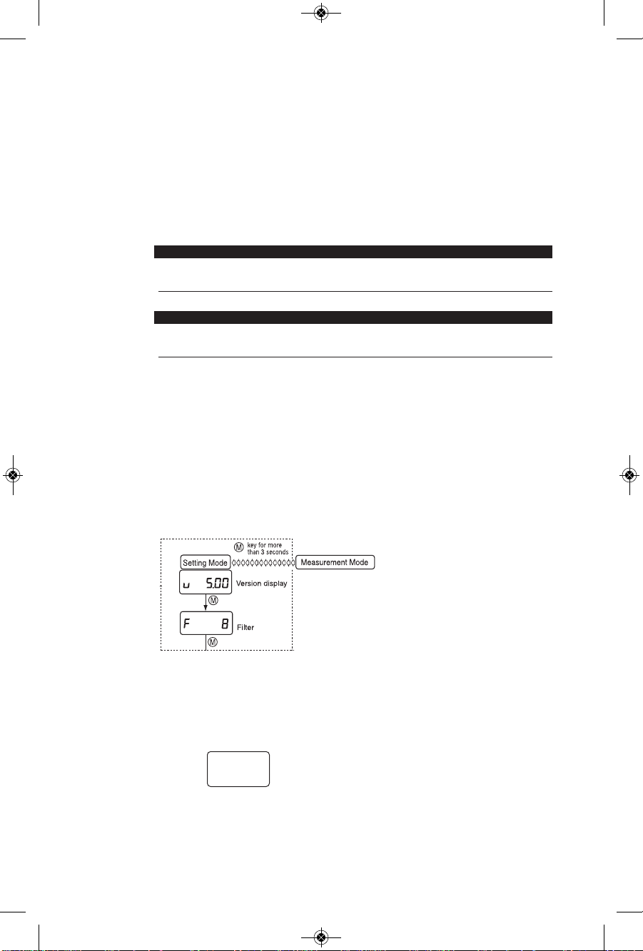
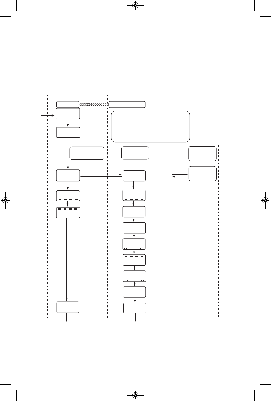
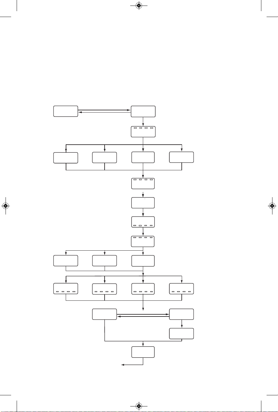
FIVE FUNCTIONS available to the User via “Setting Mode”. To enter the “Set-
ting Mode” hold (M) key for more than 3 seconds.
(See last page for complete Setting Mode menu.)
A. Filter (Damping)
The filter is based on the moving average of the pressure data to decrease display “bounce” and to smooth the analog output due to system
pressure fluctuations at the user’s discretion.
Five selections: (0, 2, 4, 8 and 16 seconds), Use
$#
keys to change value.
If “0” is selected the filter is not applied.
B. Re-scaling in “inH
2
O” units: “Pressure Display Mode” allows for zero
(4mA) and span (20ma) adjustment of –10 to +110% Span respectively.
Note: 1. See menu schematic on last page for detail.
2. Must be in “Pressure Display Mode” option within “Setting Mode,”
this is noted on the screen by
Use $#keys to move between “Pressure Display Mode” and
“Linear Display Mode” which is for re-scaling in “Arbitrary” units.
Note: Holding the button for more than
3 seconds returns to display mode.
n non
-
Omega PX5200 I&M011 10192 (GC52) QS Rev. B _layout 5/18/12 2:48 PM Page 8
Page 9
9
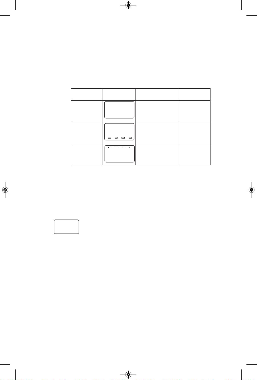
3. To adjust Output Zero Point (4mA) and Output Span Point
(20mA) the unit must be in the functional area as noted below
while adjustment is via
$ #
keys. The value shown is a percentage of the pressure range (span) as noted on the product label
(ex. If product was supplied as a 0-40 IWC range and the user desired the Output Zero Point (4mA) to be “moved” from 0 IWC to 20
IWC then Output Zero Point would be 50.0 which is 50%.
C. Re-scaling in “Arbitrary” units, “Linear Display Mode.” This function
allows the user to establish a linear relationship from the standard “inH
2
O”
unit to any user defined unit.
Note: See menu schematic on last page. Unit must be in “Linear Display
Mode” option within “Setting Mode”, this is noted on the screen by
Use $#keys to move between “Linear Display Mode” and “Pressure
Display Mode.”
a 90.0
a 10.0
n non
-
Note: For setting of zero point and span point in the analog
output, input the percent value over the pressure range.
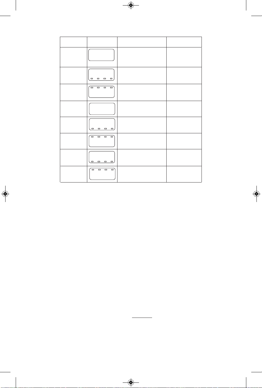
Setting LCD Setting Setting
Item Display Description Range
Display Selection of non:pressure
mode pressure display display mode
mode : non Lin: linear
display mode
Output Analog Pressure
zero point output zero point range:–10
(4mA) : 10.0 (%Span) to 110% Span
.
Output Analog Pressure
span point output span point range:–10
(20mA) : 90.0 (%Span) to 110% Span
Values shown below are from I&M manual.
n L;n
-
Omega PX5200 I&M011 10192 (GC52) QS Rev. B _layout 5/18/12 2:48 PM Page 9
Page 10
10
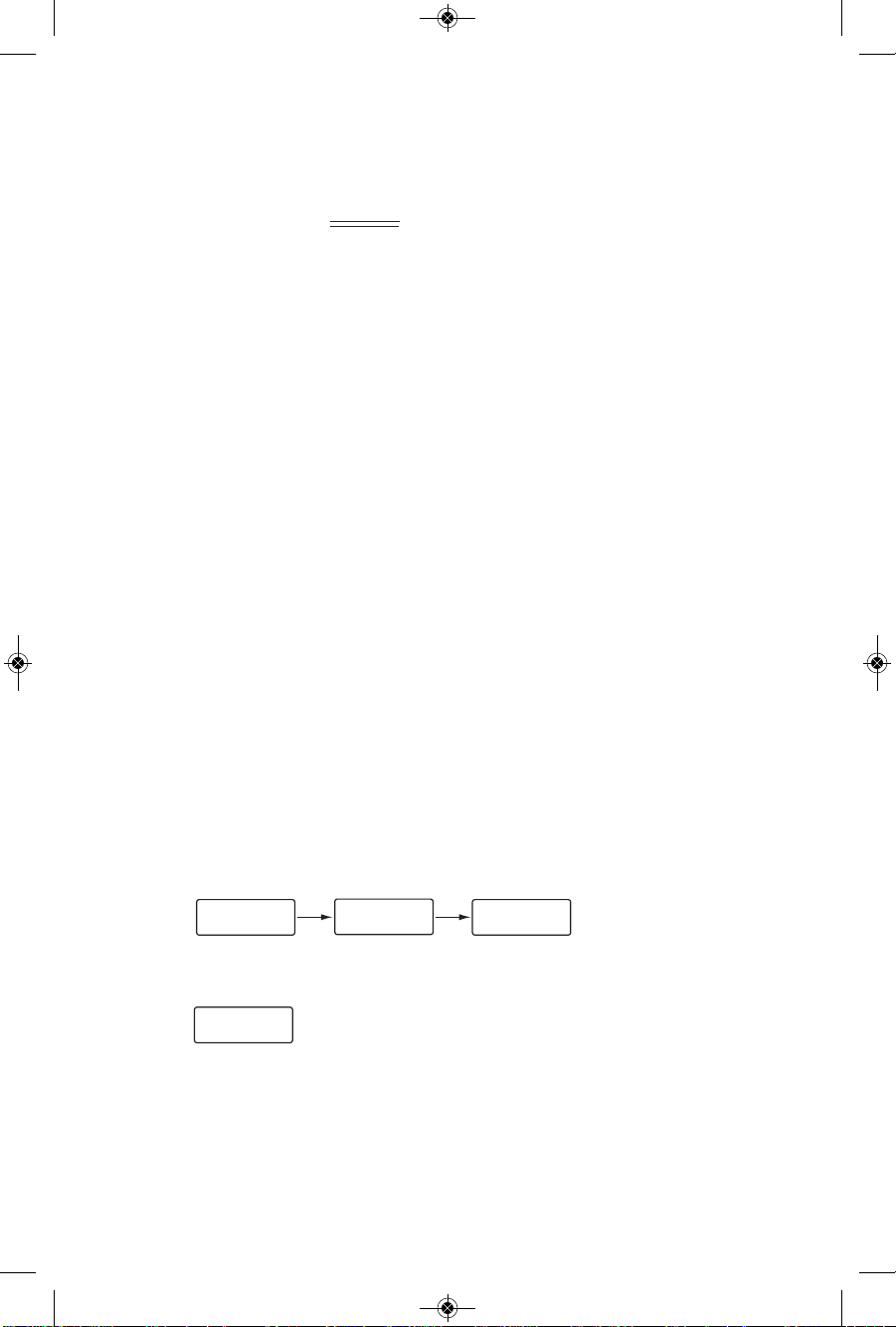
Setting LCD Setting Setting
Item Display Description Range
n00l0n
Selection of linear display
mode: Lin
non: Differential
pressure display
mode; Lin: Linear
display mode
Display mode
-
-
p0 -20
Min. differential pressure
corresponding to OFFSET
:20.0(inH
2
O)
Differential pressure range:
0 to 75% Span
Min. differential pressure
Max. differential pressure
corresponding to FULL
SCALE
:120(inH
2
O)
Differential
pressure range:
25 to 100%Span
Max. differential pressure
p0-120
Display after decimal
point Number of digits:
1(digit)
0,1,2,3 digit
Decimal point
position
d0-001
d0-00.0
d0-50.0
OFFSET corresponding
min. differential pressure
: 0.0 (m)
–1999 to 1999
OFFSET
FULL SCALE corresponding to max. differential
pressure
:50.0 (m)
–1999 to 1999
FULL SCALE
a0-50.0
Analog output zero point
: (4mA): 0.0 (%Span)
Max. display span:
–10 to 110% Span
Output zero
point
a0100.0
Analog output span point
: (20mA): 100.0 (%Span)
Max. display span:
–10 to 110%Span
Output span
point
D. Flow Measurement/Square Root Extraction Mode
Mode Square
Square Root Display Mode
Combining the sensing elements (orifice and pitot tube) with this product,
the mode is used for the display of the momentary flow rate, integrated
volume and for analog output corresponding to the momentary flow rate.
(1) Momentary flow rate
The momentary flow rate display has the maximum display span from
zero to the maximum momentary flow rate. The Momentary flow rate
display span depends on the setting of the zero point and span point
of the analog output as shown in (2) analog output. It can display 0 to
105%F.S. display span. The scaling method of momentary flow rate
can be performed only by setting the maximum momentary flow rate
and then generate differential pressure using the following square root
formula.
Momentary flow rate Dx is expressed by the square root formula (a),
and can be calculated only by measuring the generated differential
pressure Px (percent value over the differential pressure range).
Dx = k x
P
x(%)
(a)
100(%)
公
Note: Values shown are from example in I&M manual.
Omega PX5200 I&M011 10192 (GC52) QS Rev. B _layout 5/18/12 2:48 PM Page 10
Page 11
11
k =
D
m00
Pm
100
公
In addition, the coefficient k is determined by substituting the maximum
momentary flow rate Dm, which is measured from the formula (a), and
the then generated differential pressure Pm into the formula (b).
• The differential pressure generated during the maximum momentary
flow rate can be set in the range of 25 to 100%F.S. of the differential
pressure range.
• The setting range for values of the maximum momentary flow rate is 0
to 1999. Note: The decimal point can be set arbitrarily.
• When the display resolution lowers and the wobbling of momentary flow
rate increases in the low flow domain of the differential pressure flow
meter, the domain (below the set value) will be forcedly indicated as zero
by means of the low-cut for momentary flow rate.
Moreover, the analog output has a fixed value of 4mA at the zero point.
For setting of low-cut, input the percent value over the maximum display
span. Its range is 0 to 30%F.S. and the decimal point position can be set
up to one digit after decimal point as fixed point.
(2) Analog output
The zero point (4mA) and span point (20mA) of analog output can be
set in the range of 0 to 110%F.S. of the maximum display span (0 to
maximum momentary flow rate). The span between the zero point and
the span point in this analog output is the momentary flow rate display
span.
(3) Integrated volume
• The units of integrated volume include two standards: Time factor
and flow rate volume factor.
• The number of digits of integrated volume display is
a maximum of 6 figures (999999); the display will return to 0 once the
maximum reading has been met.
999999
0
0
overflows
clr
• The zero reset of an integrated volume is executed by pressing S key for
more than 3 seconds and displaying "cLr" (clear) for 2 seconds.
• As backup in case of POWER OFF, the integrated volume value is
stored in the nonvolatile memory for every hour. After power returns,
integration starts from the integrated volume value stored in the memory.
• Integration is halted during the "FFF" display at the time of
differential pressure range OVER .
(b)
Omega PX5200 I&M011 10192 (GC52) QS Rev. B _layout 5/18/12 2:48 PM Page 11
Page 12
12
• The indicated value which is blinking is integrated during the "blink"
display at the time of momentary flow rate display span OVER.
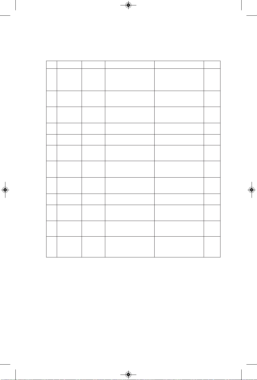
Flow Measurement/Square Root Extraction Mode
No.
Setting Item LCD Display
Setting Description Setting Range
Default
Display mode
n~ roT
Selection for flow measurement/ square root extraction
mode
non: Differential pressure
display mode Lin: Linear
display mode Rot: Square
root display mode
non
Maximum
differential
selection
1
p. 400
Maximum differential pressure relating to the flow rate
25 to 100% F.S. of sensor
range
100.0%
of sensor
range
Flow rate decimal pt. position
D 0
Displays of value after decimal point, # of digits
0,1,2,3 digit
0
Max. momentary flow
D 1000
Max. momentary of flow
using arbitrary units
0 to 1999
1000
Low cut
l 0.0
Forces display and output to
zero
0.0 to 30.0% F.S. of max.
display span
0.0
Output zero
point
2
A 0.0
Momentary flow rate of analog output zero point (4mA):
100.0% F.S.
–10 to 100% F.S. of max.
display span
0.0
Output span
point
2
A100.0
Momentary flow rate of analog output zero point
(20mA): 100.0% F.S.
–10 to 100% F.S. of max.
display span
100.0
Time factor
U SE[
Measurement of max. momentary flow rate over time
selected
Seconds, minutes or hours
Sec
21
Flow rate volume factor
U 1
Flow rate x time selected 1,10,100,1000
1
22
Display
switch setting
s bT
Selection of display switching
method of momentary flow
rate and integrated volume
ti = automatic
bt = manual
bt
23
Switch time
interval
T 5
Selection for ti: automatic
Displays switching time interval in seconds
1 to 10 seconds (10 stage)
5
24
Loop check
3
c 0.0
Output check using arbitrary
value – displays pressure
correlating to the 4 to 20mA
signal
Display: momentary flow
rate display span
Analog output: 4 to 20mA
0.0 to 100.0%
0
(4.0mA)
(1) In the setting of a differential pressure the decimal point position is fixed for each differential pressure range.
The max. differential pressure can be set from the value which is 25%F.S of the differential pressure range above the
minimum differential pressure.The values under 25%F.S. cannot be increased or decreased by T, S key.
(2) For setting zero point and span point of the analog output, input the percent value over the maximum display span (be-
tween OFFSET and FULL SCALE). Its decimal point position can be set up to one digit after the decimal point (xx.x).
(3) Regardless of generated differential pressure or low-cut, the loop check can be changed arbitrarily linking the
momentary flow rate display with the analog output using the T, S keys. This example of LCD display shows
the display set to span point.
Omega PX5200 I&M011 10192 (GC52) QS Rev. B _layout 5/18/12 2:48 PM Page 12
Page 13
13
u
M
u
M
u
M
u
M
u
M
u
M
u
M
u
M
u
M
u
M
u
M
u
M
u
M
u
M
u
M
u
M
a
b
e
c
d
f
g
h
i
j
k
l
u 6.00
f 2
n non
n l n
a 10.0
a 90.0
[ 1.00[ 1.00
p 20.0
p 120.0
d 1
d 0.0
d 50.0
a 0.0
a 100.0
[ 50.0
-
`
-
-
Linear display
mode setting
Differential pressure
display mode setting
Differential
pressure
display mode
Output span
point pressure
Output zero
point pressure
Loop check
(zero point)
Version display
Filter
Linear display
mode
Min. pressure
(Re-scaling in
“inH
2
O” units)
(Re-scaling in arbitrary
user defined units)
Max. pressure
Decimal point
position
OFFSET
Full scale
Output zero
point
Output span
point
Loop check
(span point)
Basic key operation
The setting item is changed by
u
M key.
The set value is changed or selected by
▲ key or ▼ key. When changing the value,
it is increased or decreased by pressing
▲ key or ▼ key, respectively.
(Refer to next page)
key for more
than 3 seconds
Setting Mode
Measurement Mode
m
Flow
Measurement
Mode
See
Page 6
Complete Setting Mode Menu
(4) Display switching method of momentary flow rate and integrated
volume
Display switching methods of momentary flow rate and integrated volume include the automatic switching display method to display them
by turns at intervals of fixed time (1 to 10 seconds) and the manual
switching display method to change the display by pressing (M) key.
Omega PX5200 I&M011 10192 (GC52) QS Rev. B _layout 5/18/12 2:48 PM Page 13
Page 14
14
u
M
u
M
u
M
u
M
u
M
N ROT
d 0 d i d Z d 3
a 100.0
L 0.0
P. 4.00
a 0.0
U SE1
U SE( U houU n~In
U 10 U 100 U 1000
Flow Measurement Mode
(Square Root Extraction Settings)
Refer to
Page 5
b Flow Measurement / Square Root
Extraction Mode
n Maximum Differential
Selection (Exam ft:4in)
o Flow Rate
Decimal Point
Position
5 Bt
u22 Display Switch
Setting
u
23 Switch Time
Interval
u
24 Loop Check
Returns to
Setting Mode
See Page 5
q Low Cut
s Output Span Point
t Time Factor
u
M
u
M
u
M
u
M
u
M
u
M
u
M
u
M
p Maximum Momentry
Flow
C
D
C
D
C
D
C
D
C
D
t 5
c 0.0
u21 Flow Rate
Volume Factor
C
D
C
D
C
D
C
D
u
M
r Output Zero Point
u22
5 t;
D 1000
Flow Measurement Mode (Square Root Extraction) Setting
E. Loop Check: Use to send a 4-20mA signal meant to simulate applied
pressure, can be accessed either through Pressure Display Mode or Linear
Display Mode. See “Complete Setting Mode Menu”; Loop Check is noted
on the screen with a prefix
“
(
”
. The display is indicating in actual units and
starts at the zero (4mA) point.
If $button is pressed, the linear display will auto increment by linkage be-
tween the linear display and the analog output. By continuing to press #button, auto decrement will occur. Release the button at the desired indication.
Omega PX5200 I&M011 10192 (GC52) QS Rev. B _layout 5/18/12 2:48 PM Page 14
Page 15
15
4. WIRING
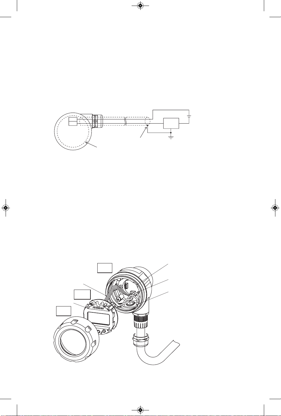
Power supply requirements, 12-36Vdc, note installation
recommendations as follows:
Terminal Strip: SMKDSP1.5/2-5.08 Phoenix contact
A. Cable Requirements
• Two core shielded cable
• Cable outer diameter: 0.35˝ to 0.47˝ (9-12mm)
Required for proper installation with cable gland option
• Wire Gauge: 14-22 AWG (multi-strand or solid)
B. Wiring Instructions
• Do not run pressure transmitter cable / wires within the same conduit as high
voltage (line power) line to reduce the potential for noise (interference).
Use dedicated conduit on PX5200 cables / wires for optimum results.
• Cable diameter, specified above, must be maintained when using the Cable
Gland termination to retain environmental ratings.
• When connecting shield / drain wire, only connect one end which should be at
the received ground.
• Wire stripping instructions; remove cable jacket 2-3˝ and strip wires 0.25˝.
Shield / drain wire should not be exposed at the pressure transmitter termination.
+
−
Terminal box
Display (board)
Shield
Power source
+ −
Receiver
Transmission cable
CASE
DISPLAY
CAP
Inside sensor Line
LCD holder
Notch
Transmission cable
(Twist)
Sheath
PX5200
Omega PX5200 I&M011 10192 (GC52) QS Rev. B _layout 5/18/12 2:48 PM Page 15
Page 16
16
Display
Wire terminals
Wire
Turn with a screwdriver
LCD clips (4)
Display board
Power supply
terminal block
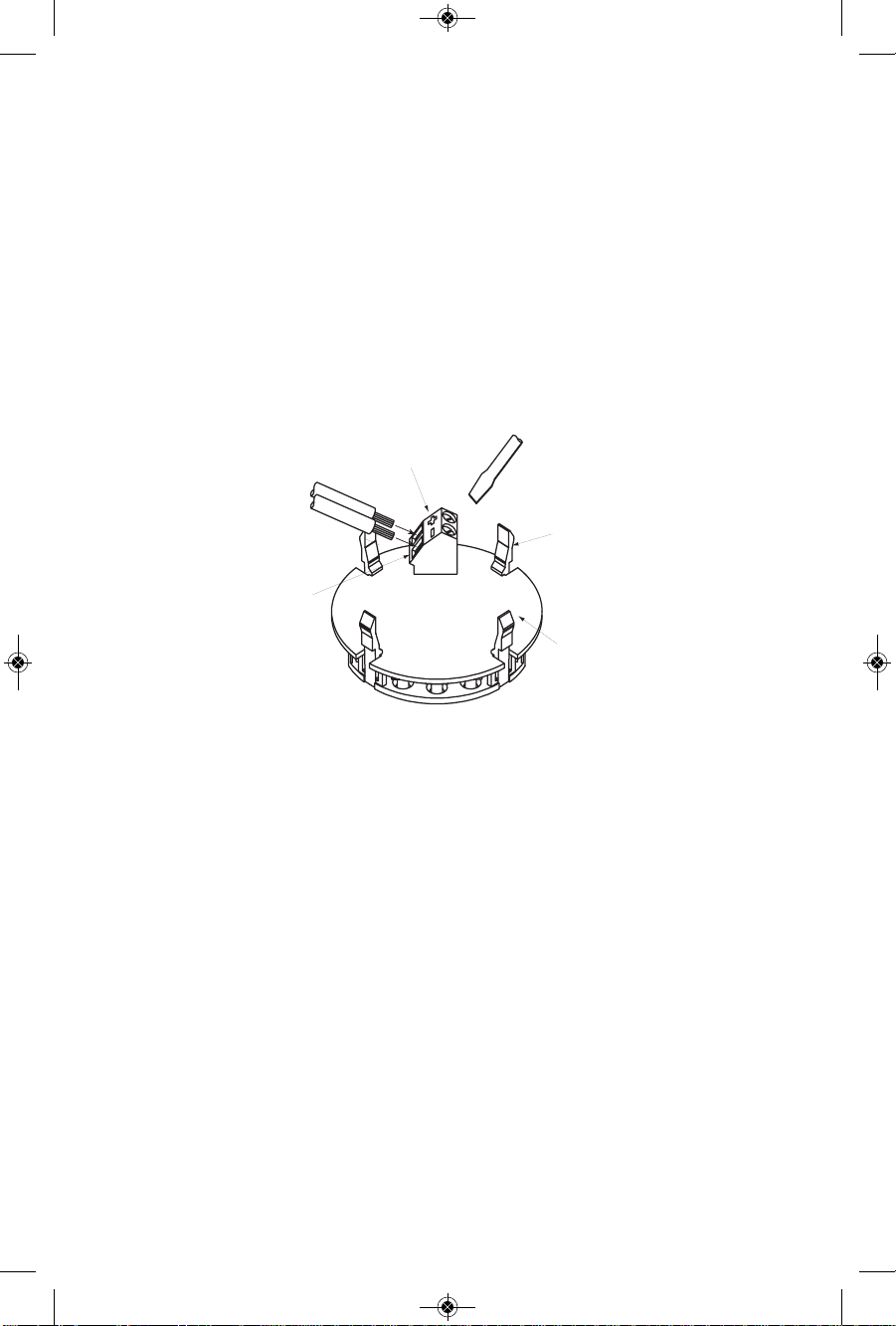
• Remove cover and carefully remove the display to access the terminal strip,
take care not to mishandle the display and associated electronics.
• Turn display over to expose terminal strip, make positive and negative connections; insert wire equal to the recommended strip length (0.25˝).
• After completing connections, align the retaining clips of the display with the
housing’s notches and carefully place into the housing. Be sure that the internal sensor ribbon cable does not cross the power supply lines just installed.
• Be sure to properly tighten the sealing grommet when using the Cable Gland
before applying tension to the cable; the cable gland provides strain relief and
environmental sealing.
• Tighten PX5200 cover to maintain environmental rating.
• Connect to power source and receiver, than apply power to confirm correct
wiring.
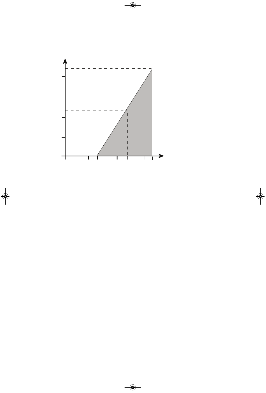
• Power Supply Requirements: Although the 4-20mA signal can travel over long
distances, a very common issue to arise involves inadequate power at the
pressure transmitter – this results in voltage drop across the loop. Be sure to
review the accompanying table to determine whether the 12-36Vdc has been
received at the pressure transmitter.
Omega PX5200 I&M011 10192 (GC52) QS Rev. B _layout 5/18/12 2:48 PM Page 16
Page 17
17
1000
750
500
250
0
0 322010
1020
30
Load Limitations 4-20mA Output Only
12 24
545
OPERATING
REGION
Loop Resistance (V)
LOOP SUPPLY VOLTAGE
V
min
= 12V+[.022A*RL)]
*Includes a 10% safety factor
RL= RS+ R
W
RL= Loop Resistance (ohms)
R
S
= Sense Resistance (ohms)
R
W
= Wire Resistance (ohms)
Omega PX5200 I&M011 10192 (GC52) QS Rev. B _layout 5/18/12 2:48 PM Page 17
Page 18
18
Omega PX5200 I&M011 10192 (GC52) QS Rev. B _layout 5/18/12 2:48 PM Page 18
Page 19

WARRANTY/DISCLAIMER
OMEGA ENGINEERING, INC. warrants this unit to be free of defects in materials and
workmanship for a period of 13 months from date of purchase. OMEGA’s WARRANTY adds
an additional one (1) month grace period to the normal one (1) year product warranty to
cover handling and shipping time. This ensures that OMEGA’s customers receive maximum
coverage on each product.
If the unit malfunctions, it must be returned to the factory for evaluation. OMEGA’s Customer
Service Department will issue an Authorized Return (AR) number immediately upon phone
or written request. Upon examination by OMEGA, if the unit is found to be defective, it
will be repaired or replaced at no charge. OMEGA’s WARRANTY does not apply to defects
resulting from any action of the purchaser, including but not limited to mishandling, improper
interfacing, operation outside of design limits, improper repair, or unauthorized modification.
This WARRANTY is VOID if the unit shows evidence of having been tampered with or shows
evidence of having been damaged as a result of excessive corrosion; or current, heat, moisture
or vibration; improper specification; misapplication; misuse or other operating conditions
outside of OMEGA’s control. Components in which wear is not warranted, include but are not
limited to contact points, fuses, and triacs.
OMEGA is pleased to offer suggestions on the use of its various products. However,
OMEGA neither assumes responsibility for any omissions or errors nor assumes
liability for any damages that result from the use of its products in accordance
with information provided by OMEGA, either verbal or written. OMEGA warrants
only that the parts manufactured by the company will be as specified and free of
defects. OMEGA MAKES NO OTHER WARRANTIES OR REPRESENTATIONS OF ANY
KIND WHATSOEVER, EXPRESSED OR IMPLIED, EXCEPT THAT OF TITLE, AND ALL
IMPLIED WARRANTIES INCLUDING ANY WARRANTY OF MERCHANTABILITY AND
FITNESS FOR A PARTICULAR PURPOSE ARE HEREBY DISCLAIMED. LIMITATION
OF LIABILITY: The remedies of purchaser set forth herein are exclusive, and the
total liability of OMEGA with respect to this order, whether based on contract,
warranty, negligence, indemnification, strict liability or otherwise, shall not exceed
the purchase price of the component upon which liability is based. In no event shall
OMEGA be liable for consequential, incidental or special damages.
CONDITIONS: Equipment sold by OMEGA is not intended to be used, nor shall it be used: (1)
as a “Basic Component” under 10 CFR 21 (NRC), used in or with any nuclear installation or
activity; or (2) in medical applications or used on humans. Should any Product(s) be used in or
with any nuclear installation or activity, medical application, used on humans, or misused in
any way, OMEGA assumes no responsibility as set forth in our basic WARRANTY / DISCLAIMER
language, and, additionally, purchaser will indemnify OMEGA and hold OMEGA harmless from
any liability or damage whatsoever arising out of the use of the Product(s) in such a manner.
Direct all warranty and repair requests/inquiries to the OMEGA Customer Service Department.
RETURN REQUESTS/INQUIRIES
BEFORE RETURNING ANY PRODUCT(S) TO OMEGA, PURCHASER MUST OBTAIN AN
AUTHORIZED RETURN (AR) NUMBER FROM OMEGA’S CUSTOMER SERVICE DEPARTMENT
(IN ORDER TO AVOID PROCESSING DELAYS). The assigned AR number should then be
marked on the outside of the return package and on any correspondence.
The purchaser is responsible for shipping charges, freight, insurance and proper packaging to
prevent breakage in transit.
FOR WARRANTY RETURNS, please have
the following information available BEFORE
contacting OMEGA:
1. Purchase Order number under which
the product was PURCHASED,
2. Model and serial number of the product
under warranty, and
3. Repair instructions and/or specific
problems relative to the product.
OMEGA’s policy is to make running changes, not model changes, whenever an improvement is possible.
This affords our customers the latest in technology and engineering.
OMEGA is a registered trademark of OMEGA ENGINEERING, INC.
© Copyright 2017 OMEGA ENGINEERING, INC. All rights reserved. This document may not be copied, photocopied,
reproduced, translated, or reduced to any electronic medium or machine-readable form, in whole or in part, without
the prior written consent of OMEGA ENGINEERING, INC.
FOR NON-WARRANTY REPAIRS,
consult
OMEGA for current repair charges. Have the
following information available BEFORE
contacting OMEGA:
1. Purchase Order number to cover the
COST of the repair,
2. Model and serial number of the product, and
3. Repair instructions and/or specific problems
relative to the product.
Page 20
Where Do I Find Everything I Need for
Process Measurement and Control?
OMEGA…Of Course!
Shop online at omega.com
TEMPERATURE
MU
Thermocouple, RTD & Thermistor Probes, Connectors, Panels & Assemblies
MU
Wire: Thermocouple, RTD & Thermistor
MU
Calibrators & Ice Point References
MU
Recorders, Controllers & Process Monitors
MU
Infrared Pyrometers
PRESSURE, STRAIN AND FORCE
MU
Transducers & Strain Gages
MU
Load Cells & Pressure Gages
MU
Displacement Transducers
MU
Instrumentation & Accessories
FLOW/LEVEL
MU
Rotameters, Gas Mass Flowmeters & Flow Computers
MU
Air Velocity Indicators
MU
Turbine/Paddlewheel Systems
MU
Totalizers & Batch Controllers
pH/CONDUCTIVITY
MU
pH Electrodes, Testers & Accessories
MU
Benchtop/Laboratory Meters
MU
Controllers, Calibrators, Simulators & Pumps
MU
Industrial pH & Conductivity Equipment
SM
DATA ACQUISITION
MU
Communications-Based Acquisition Systems
MU
Data Logging Systems
MU
Wireless Sensors, Transmitters, & Receivers
MU
Signal Conditioners
MU
Data Acquisition Software
HEATERS
MU
Heating Cable
MU
Cartridge & Strip Heaters
MU
Immersion & Band Heaters
MU
Flexible Heaters
MU
Laboratory Heaters
ENVIRONMENTAL
MONITORING AND CONTROL
MU
Metering & Control Instrumentation
MU
Refractometers
MU
Pumps & Tubing
MU
Air, Soil & Water Monitors
MU
Industrial Water & Wastewater Treatment
MU
pH, Conductivity & Dissolved Oxygen Instruments
M5091/0817
 Loading...