

Page 1
WARRANTY/DISCLAIMER
OMEGA ENGINEERING, INC. warrants this unit to be free of defects
in materials and workmanship for a period of 13 months from
date of purchase. OMEGA’s WARRANTY adds an additional one (1)
month grace period to the normal one (1) year product warranty
to cover handling and shipping time. This ensures that OMEGA’s
customers receive maximum coverage on each product.
If the unit malfunctions, it must be returned to the factory for
evaluation. OMEGA’s Customer Service Department will issue an
Authorized Return (AR) number immediately upon phone or written
request. Upon examination by OMEGA, if the unit is found to be
defective, it will be repaired or replaced at no charge. OMEGA’s
WARRANTY does not apply to defects resulting from any action of
the purchaser, including but not limited to mishandling, improper
interfacing, operation outside of design limits, improper repair,
or unauthorized modification. This WARRANTY is VOID if the unit
shows evidence of having been tampered with or shows evidence of
having been damaged as a result of excessive corrosion; or current,
heat, moisture or vibration; improper specification; misapplication;
misuse or other operating conditions outside of OMEGA’s control.
Components in which wear is not warranted, include but are not
limited to contact points, fuses, and triacs.
OMEGA is pleased to offer suggestions on the use of its various
products. However, OMEGA neither assumes responsibility for
any omissions or errors nor assumes liability for any damages
that result from the use if its products in accordance with
information provided by OMEGA, either verbal or written.
OMEGA warrants only that the parts manufactured by the
company will be as specified and free of defects. OMEGA
MAKES NO OTHER WARRANTIES OR REPRESENTATIONS OF
ANY KIND WHATSOEVER, EXPRESSED OR IMPLIED, EXCEPT
THAT OF TITLE, AND ALL IMPLIED WARRANTIES INCLUDING
ANY WARRANTY OF MERCHANTABILITY AND FITNESS
FOR A PARTICULAR PURPOSE ARE HEREBY DISCLAIMED.
LIMITATION OF LIABILITY: The remedies of purchaser set forth
herein are exclusive, and the total liability of OMEGA with
respect to this order, whether based on contract, warranty,
negligence, indemnification, strict liability or otherwise,
shall not exceed the purchase price of the component upon
which liability is based. In no event shall OMEGA be liable for
consequential, incidental or special damages.
CONDITIONS: Equipment sold by OMEGA is not intended to be used,
nor shall it be used: (1) as a “Basic Component” under 10 CFR 21 (NRC),
used in or with any nuclear installation or activity; or (2) in medical
applications or used on humans. Should any Product(s) be used in or
with any nuclear installation or activity, medical application, used on
humans, or misused in any way, OMEGA assumes no responsibility
as set forth in our basic WARRANTY/DISCLAIMER language, and,
additionally, purchaser will indemnify OMEGA and hold OMEGA
harmless from any liability or damage whatsoever arising out of the use
of the Product(s) in such a manner.
RETURN REQUESTS/INQUIRIES
Direct all warranty and repair requests/inquiries to the OMEGA
Customer Service Department. BEFORE RETURNING ANY
PRODUCT(S) TO OMEGA, PURCHASER MUST OBTAIN AN
AUTHORIZED RETURN (AR) NUMBER FROM OMEGA’S CUSTOMER
SERVICE DEPARTMENT (IN ORDER TO AVOID PROCESSING
DELAYS). The assigned AR number should then be marked on the
outside of the return package and on any correspondence.
FOR WARRANTY RETURNS,
please have the following
information available BEFORE
contacting OMEGA:
1. Purchase Order number under
which the product was
PURCHASED,
2. Model and serial number of
the product under warranty, and
3. Repair instructions and/or
specific problems relative to
the product.
OMEGA’s policy is to make running changes, not model changes,
whenever an improvement is possible. This affords our customers
the latest in technology and engineering.
OMEGA is a registered trademark of OMEGA ENGINEERING, INC.
© Copyright 2015 OMEGA ENGINEERING, INC. All rights reserved.
This document may not be copied, photocopied, reproduced,
translated, or reduced to any electronic medium or machine-readable
form, in whole or in part, without the prior written consent of OMEGA
ENGINEERING, INC.
MQS5545/1215
FOR NON-WARRANTY REPAIRS,
consult OMEGA for current repair
charges. Have the following
information available BEFORE
contacting OMEGA:
1. Purchase Order number to
cover the COST of the repair or
calibration,
2. Model and serial number of the
product, and
3. Repair instructions and/or specific
problems relative to the product.
5
Step 8: Configure Device
“Next” and “OK” to program the transducer. Click
“Exit” or “Setup Another Transducer”.
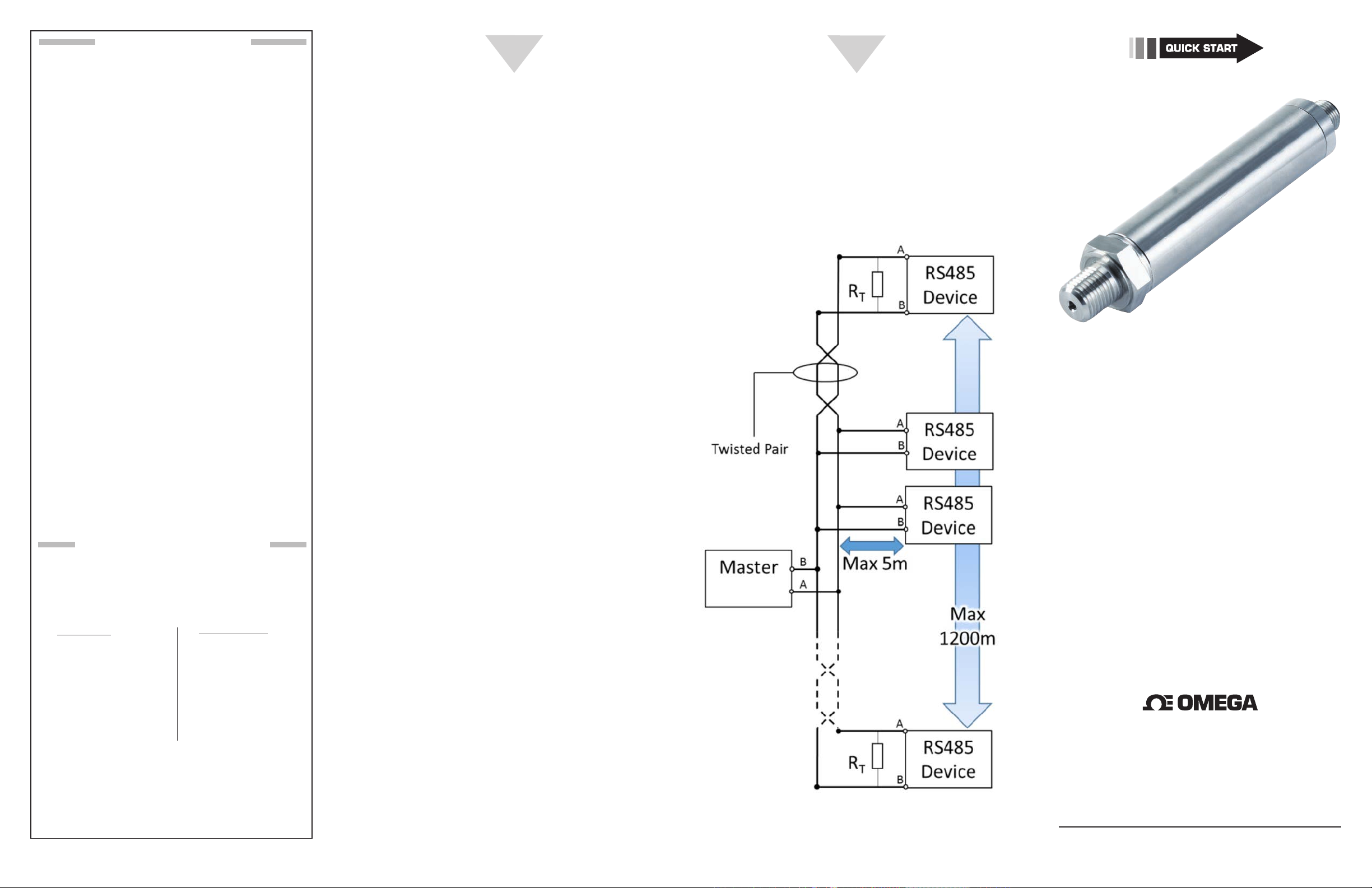
RS485 Bus Requirements
Consideration should be given to apply best practices
for the RS485 bus.
1. Proper wiring topology: Wire in a multi-drop
configuration. Minimize stub lengths (max length 5
m). A stub is a branch off of the main RS485 trunk line.
External Referenced Materials
Omega PX409-485 Transducer Command Reference
(TCR): Defines the protocol used to communicate with
PX409-485. Use this if writing your own app or using
a terminal program. FTP site: ftp://ftp.omega.com/
public/DASGroup/products/USBH/
Texas Instruments App Note SLLA272B
http://www.ti.com/lit/an/slla272b/slla272b.pdf
TIA application recommendation document TSB-89
6
2. Use twisted pair cable designed for RS485 busses: We
recommend UL 2919 style cable, 22-24 AWG, 120 Ohm
Nom. Char. Impedance, 42pF/m Nom. Capacitance,
100% foil, 90% braided shield with drain wire. Signals
A and B should be routed in one twisted pair. It is
recommended to tie drain wire to shield connection
on PX409-485 side, and to earth ground on supply
side. The PX409-485 case must be grounded.
3. Cable routing and length up to 1200 meters, but
might be reduced by a noisy environment or other
installation issues.
PX409-485/PXM409-485
High Speed RS485 Pressure Transmitter
4. Number of devices on the bus: Maximum of 16 units
on the bus when requiring a sample rate of 1 sample
per second. The PX409-485 is a 1/8 unit load.
5. Termination: it is recommended that RS485 busses are
terminated at each end with a 120 Ohm resistor across
A and B signals for proper impedance matching.
The PX409-485 has a built-in 120 Ohm resistor that is
software enabled.
®
omega.com [email protected]
Servicing North America:
Customer Service: 1-800-622-2378 (USA & Canada Only)
Engineering Service: 1-800-872-9436 (USA & Canada Only)
Tel: (203) 359-1660 Fax: (203) 359-7700
e-mail: [email protected]
Figure 6: RS485 Bus
U.S.A.: OMEGA Engineering, Inc., One Omega Dr.
P.O. Box 4047, Stamford, CT 06905-0047 USA
Toll-Free: 1-800-826-6342 (USA & Canada Only)
For Other Locations Visit omega.com/worldwide
The information contained in this document is believed to be correct, but
OMEGA accepts no liability for any errors it contains, and reserves the right to
alter specifications without notice.
Page 2
START HERE
2
3
4
Using This Quick Start Manual
Use this Quick Start Manual with your Omega
PX409-485 or PXM409-485 series high speed RS485
pressure transmitter for quick configuration of the
transducer RS485 settings and RS485 bus.
General Description
e PX409-485 pressure transmitter is an industrial
Silicon Pressure Transmitter with both a digital
RS485 and analog output. is enables you to connect and monitor multiple devices on one RS485
bus while using the analog output to provide process
control.
Connecting To A Computer
To connect to a Computer a RS485 hardware
interface must be used, which can be purchased
from Omega. You can use either a RS485 to USB
converters, or card that plugs directly into the PC’s
motherboard.
Follow the setup instructions of the interface before
connecting the PX409-485, and congure the
interface as Half Duplex, 115200 Baud, No Parity, 8
Data bits, 1 Stop Bit, No Hardware Flow control.
Pinout Of PX409-485
PX409-485 has an integral 8 pin Type-A Male
M12 connector. Mating connectors are available at
Omega.com part number: M12.8-S-F-FM
ELECTRICAL PINOUT
Pin 1: Vout (+) ANALOG
Pin 2: SUPPLY (+)
Pin 3: B (RS485)
Pin 4: A (RS485)
Pin 5: SUPPLY (-)
Pin 6: Vout (-) ANALOG
Pin 7: DO NOT CONNECT
Pin 8: SHIELD
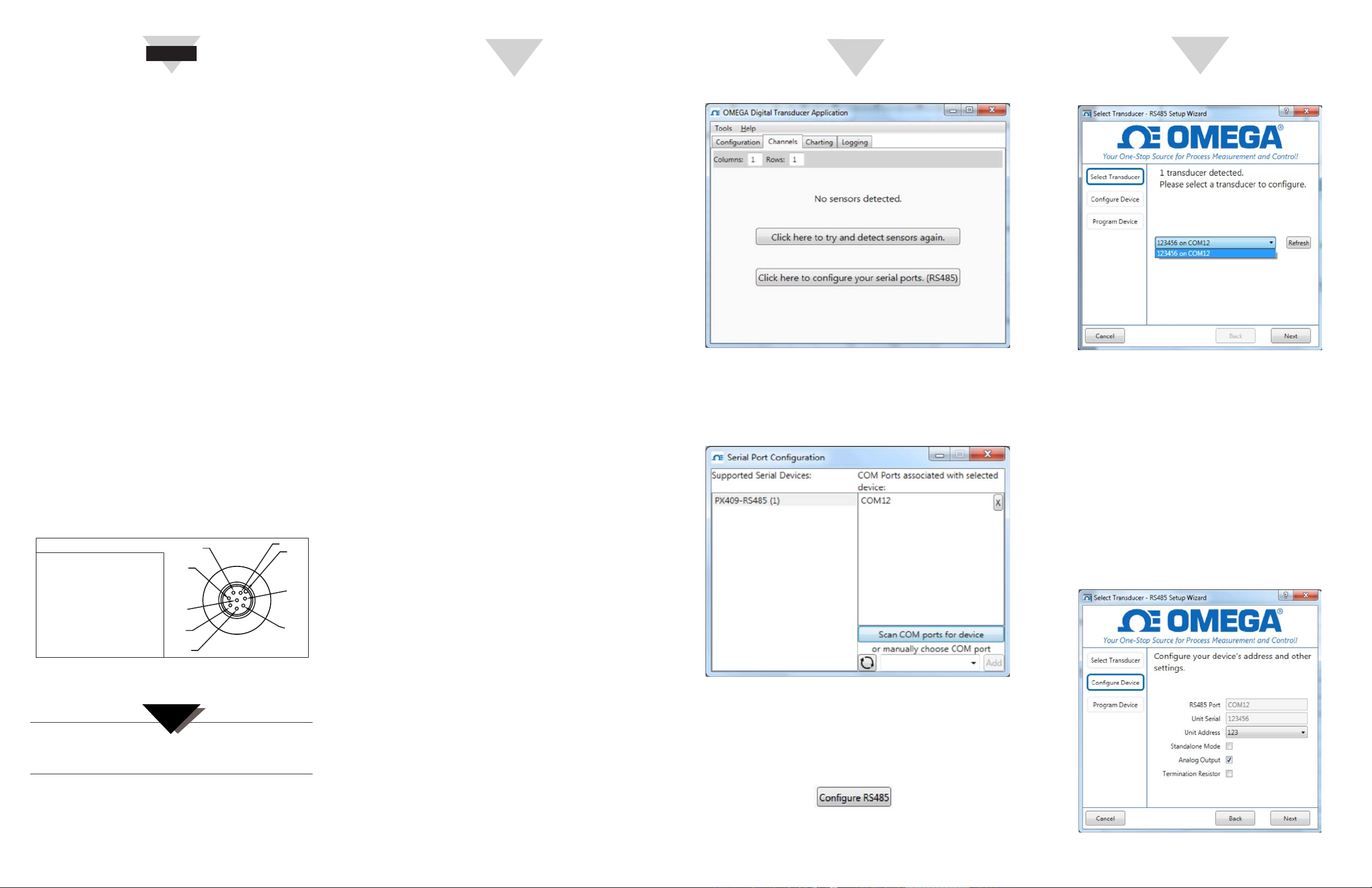
Figure 1: Electrical Pinout Of PX409-485 As Viewed
From The Connector Side.
PIN 4
PIN 8
PIN 5
PIN 6
NOTE:
PIN 3
2
3
1
4
8
7
5
6
PIN 2
KEY
PIN 1
PIN 7
An external DC power supply is required (not
included). Refer to Spec Sheet
PX409-485 Bus Modes
PX409-485 is a slave device on a bus where the
PC is the master, and only responds to commands
sent by the master, except when the transducer is
streaming data in Standalone mode.
There are two modes that the PX409-485 can operate in:
1. Multidrop Mode: Multiple PX409-485 units can
coexist on the same RS485 bus. Each unit must have a
unique address. The master computer sends specific
commands to the addressed device. Maximum poll
rate for each transducer is 1 SPS with up to 16 units.
2. Standalone Mode: Standalone mode allows the full
bandwidth of the transducer (up to 640 SPS) to be
used. Only one PX409-485 unit is allowed on the bus
at a time. The unit is not addressed.
Digital Transducer Application (DTA)
The Digital Transducer Application is a free software
solution provided by Omega that allows you to
interface with pressure and load digital transducers
manufactured by Omega. The software enables you to
monitor, chart, and data log outputs from your devices,
while also providing a convenient way to set-up your
PX409-485 transducer.
Analog Output
The PX409-485 comes with either a 0-5 VDC (-5V Part
Number suffix) or 4-20 mA (-I suffix) analog output,
depending on which model you purchased. The analog
output defaults to “on”, but can be disabled using
the instructions in this document. The analog output
follows the pressure, and is not affected by the tare
feature in the DTA.
RS-485 Configuration Using The Digital
Transducer Application (DTA)
If only one PX409-485 is to be on the bus, no RS-485
configuration besides adding the termination resistor
is required. If multiple units are to be on the bus in
Multidrop mode, each unit must be physically added
to the bus one at a time, changing the address of the
newly added unit from the default of “123” to a unique
address from 001 to 127.
Step 1: Install
Digital Transducer Application, Link:
ftp://ftp.omega.com/public/DASGroup/products/
USBH/
Step 2: Connect
Transducer to the computer and power it on.
Step 3: Open
DTA software, Click “Click here to configure your serial
ports. (RS485)”. OR Tools menu → Configure Serial
Ports.
Figure 2: DTA Initial Screen
Step 4: Click
“Scan COM ports for device”. The RS485 COM port
should appear in the “COM Ports associated with
selected device” area. Close this window.
Figure 3: Serial Port Configuration Screen
Step 5: Select
1. Configuration Tab in the DTA and select a
transducer in the Channels window.
Step 6: Click
1 “Configure RS485” button
in the “Sensor Configuration” area, which will open the
RS485 Setup Wizard. Select the appropriate transducer
in the drop-down list, and click “Next”.
Figure 4: Select Transducer Screen
Step 7: Configure Device
1. Change address (123 is the default), for multidrop busses it is critical to have a unique address
for each device.
2. Standalone mode, activate this option to allow
device streaming, only one device is allowed on
the bus. Deactivate for Multidrop mode.
3. Analog Output, Deactivating this option will
disable the analog output of the device.
4. Termination resistor, enable or disable (default)
the internal 120 Ohm resistor across A and B.
Activate this option for devices that are at the
end of a BUS.
Figure 5: Configure Device Screen
 Loading...