

Page 1
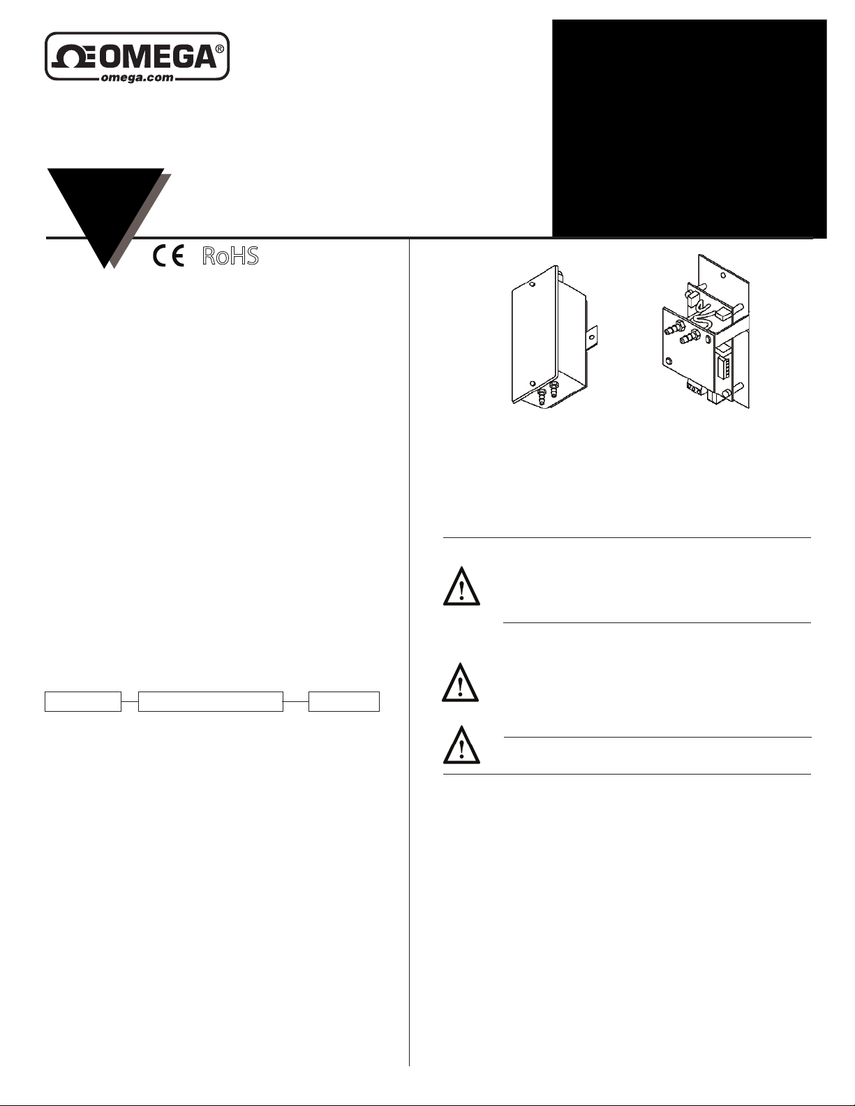
PX274, PX275, PX277, PX278 Series
Low Pressure Sensors
INSTRUCTION
SHEET
M2759/0915
Shop online at omega.comSM e-mail: [email protected]
For latest product manuals: www.omegamanual.info
RoHS
For Additional Information See PX274/275/277/278
Data Sheet
SPECIFICATIONS
Accuracy*: ±1% FS
Overpressure: 10 PSID
Supply Voltage: 12-40 VDC, 12-35 VAC (VDC output units only)
Supply Current: VDC Units - 10 mA max., mA Units - 20 mA max
Enclosure: 18 Ga C. R. Steel NEMA 4 (IP-65) or Panel Mount Chassis
Finish: Baked on enamel-PMS2GR88B
EMC Conformance: EN 55022, 55024, 61000-3-3, 61000-4-2, 3, 4, 5, 6 & 11
Compensated Temp Range: 25°F-150°F (-4°C-65°C)
T. C. Error: ±.0.0125%/°F (02%/°C)
Operating Temp Range: 0°F-175°F (-18°C-80°C)
Media Compatibility: Clean dry air or any inert gas
Environmental: 10-90%RH Non-Condensing
Termination: Unpluggable screw terminal block
Wire Size: 12 Ga max.
Load Impedance: 1.6K ohms max. at 40 VDC (mA output units)
1K ohms min. (VDC output units)
Weight: Enclosure - 1.0 lbs. (.45 kg) Panel Mount - 0.5 lbs. (.25 kg)
ORDERING INFORMATION
PACKAGING RANGE OUTPUT
274 (enclosure)
275 (panel mount)
INSTALLATION
Inspection - Inspect the package for damage. If damaged, notify the
appropriate carrier immediately. If undamaged, open the package and
inspect the device for obvious damage. Return damaged products.
R1
0 TO 0.10 / -0.05 TO +0.05
("wc)
R2
0 TO 1.0 / 0 TO 0.5 / 0 TO 0.25 /
("wc)
-0.5 TO +0.5 / -0.25 TO +0.25 /
-0.125 TO +0.125
R3
0 TO 5.0 / 0 TO 2.5 / 0 TO 1.25 /
("wc)
-2.5 TO +2.5 / -1.25 TO +1.25 /
-0.625 TO +0.625
0 TO 30 / 0 TO 15 / 0 TO 7.5 /
R4
-15.0 TO +15.0 / -7.5 TO +7.5 /
("wc)
-3.75 TO + 3.75
0 TO 25 / -12.5 TO +12.5
R5
(pa)
0 TO 250 / 0 TO 125 / 0 TO 62.5 /
R6
-125 TO +125 / -62.5 TO +62.5 /
(pa)
-31.25 TO +31.25
0 TO 1250 / 0 TO 625 / 0 TO 312.5 /
R7
-625 TO +625 / -312.5 TO +312.5 /
(pa)
-156.25 TO +156.25
0 TO 7500 / 0 TO 3750 / 0 TO 1875 /
R8
-3750 TO +3750 / -1875 TO +1875 /
(pa)
-937.5 TO +937.5
mA
(4-20 mA
2-wire)
VDC
(0-5 VDC or
0-10 VDC field
selectable)
Requirements
Mounting
Wiring
Enclosure Mount
Transducer
Panel Mount
Transducer
• Tools (not provided)
- Digital Volt-ohm Meter (DVM)
- Appropriate screwdriver for mounting screws
- Appropriate drill and drill bit for mounting screws
• Appropriate accessories
• Two #8 self-tapping mounting screws (not provided)
• Training: Installer must be a qualified, experienced technician
Warning:
• Disconnect power supply before installation to prevent electrical
shock and equipment damage.
• Make all connections in accordance with the job wiring diagram
and in accordance with national and local electrical codes. Use
copper conductors only.
Caution:
• Use electrostatic discharge precautions (e.g., use of wrist straps)
during installation and wiring to prevent equipment damage.
• Avoid locations where severe shock or vibration, excessive
moisture or corrosive fumes are present. NEMA Type 4 housings
are intended for outdoor use primarily to provide a degree of
protection against wind-blown dust, rain, and hose-directed water.
• Do not exceed ratings of the device.
Caution:
• Condensate or moisture must not enter pressure sensor ports
The PX-274/275 must be mounted as indicated by the arrows on
the enclosure. Refer to Figure 7 for mounting dimensions.
1. Remove the transducer cover using a Phillips head
screwdriver.
2. Select the mounting location.
3. Mount transducer on a vertical surface with two #8
self-tapping screws (not provided).
4. Transducer must be mounted above the pressure pick-up or a
J-Loop must be incorporated in the tubing to function as a
condensate trap.
5. Pull wires through bottom of enclosure and make
necessary connections.
6. Replace cover and make pneumatic connections.
Use maximum 12 AWG wire for wiring terminals. Use flexible 1/4"
O.D. 5/32" I.D. tubing for the high and low pressure connections.
Refer to Figures 1, 2, 3, & 4 for wiring information and Figures 5 &
6 for switch designations.
(Wiring Instructions continued on pages 2 and 3.)
Page 2
Page 2 of 4
PX274/275/277/278 Series
LOW PRESSURE SENSORS
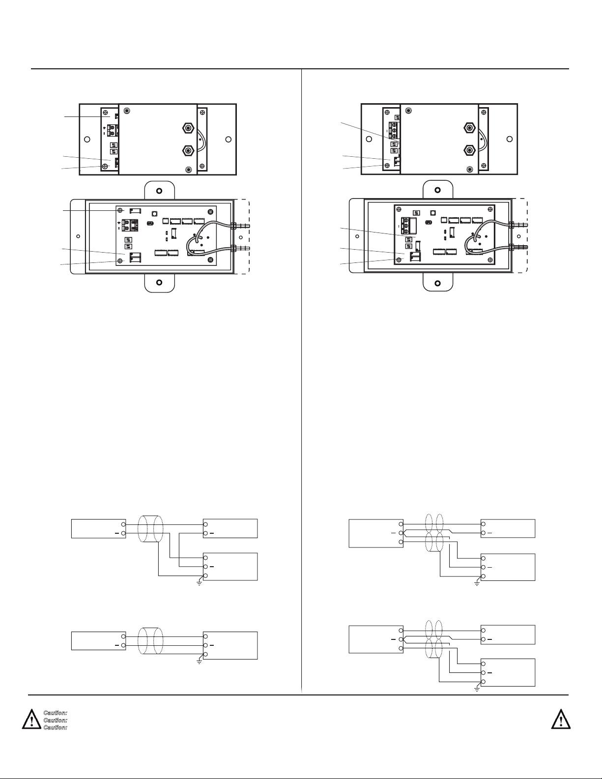
Wiring PX274/275/277/278 Units with mA Output
PX274/275/277/278 Low Pressure Transducer with mA output
Zb
Zb
MAMAC 9280
High
S1 S2
ON
Zb
Zu
ON
Zu
S
S
Zb
Low
MAMAC 9280
High
S1 S2
ON
Zu
ON
Zu
S
Low
S
PX274/275/277/278 pressure transducers with 4-20 mA output are powered
with a12-40 VDC supply.
The following describes the proper wiring of these pressure transducers with
mA output:
1. Remove the terminal block by carefully pulling it off the circuit board.
2. Locate the [+] and [-] terminal markings on the board.
3. Attach the supply voltage to the [+] lead.
4. Connect the 4-20 mA output ([-] terminal) to the controller’s input terminal.
5. Ensure that the power supply common is attached to the common bus of the
controller.
6. Re-insert the terminal block to the circuit board and apply power to the unit.
7. Check for the appropriate output signal using a DVM set on DC milliamps
connected in series with the [-] terminal.
WWiring PX274/275/277/278 Units with VDC Output
PX274/275/277/278 Low Pressure Transducer with VDC output
S3
Zb
Zu
Zb
Zu
ON
+
0
S1
ON
Zb
S2
ON
Zu
S
S
S3
+
0
S1
ON
S2
ON
Zu
S
High
Low
ON
Zb
MAMAC 9280
MAMAC 9280
High
Low
S
PX274/275/277/278 pressure transducers with VDC output are field selectable
0-5 VDC or 0-10 VDC output and can be powered with either a 12-40 VDC or
12-35 VAC.
The following describes the proper wiring of these pressure transducers with
VDC output:
1. Remove the terminal block by carefully pulling it off the circuit board.
2. Locate the [+], [-] and [O] terminal markings on the board.
3. Attach the power wires to the [+] and [-] terminals. The [-] terminal is also the
negative terminal.
4. Connect the [O] terminal, which is the positive VDC output terminal, to the
controller’s input terminal.
5. Re-insert the terminal block to the circuit board and apply power to the unit.
6. Check the appropriate VDC output using a voltmeter set on DC volts across
the [O] and [-] terminals.
TYPICAL APPLICATIONS (wiring diagrams)
Figure 1 and Figure 2 illustrate typical wiring diagrams for the mA output low
pressure transducer.
Figure 1 - Wiring for mA Low Pressure Transducers with an External DC Power
Supply
mA Output Transducer Only 12-40 VDC Power Supply
+
Figure 2 - Wiring for mA Output Transducers where the Controller or Meter has an
Internal DC Power Supply
mA Output Transducer Only
+
Caution: If you are using grounded AC, the hot wire must be on the [+] terminal. Also, if you are using a controller without built-in isolation, use an isolation transformer to supply the PX-274/275.
Caution: This product contains a half-wave rectifier power supply and must not be powered off transformers used to power other devices utilizing non-isolated full-wave rectifier power supplies.
Caution: When multiple PX274/275/277/278 units are powered from the same transformer, damage will result unless all 24G power leads are connected to the same power lead on all devices.
It is mandatory that correct phasing be maintained when powering more than one device from a single transducer.
+
Controller / Meter / Recorder
Input Signal
+
Common
Shield/Ground
Controller / Meter / Recorder
Input Signal
+
Common
Shield/Ground
TYPICAL APPLICATIONS (wiring diagrams)
Figure 3 and Figure 4 illustrate typical wiring diagrams for the VDC output low
pressure transducer.
Figure 3 - Wiring for VDC Low Pressure Transducers When Applied with External
AC Supply
VDC Output Transducer Only 12-35 VAC Transformer
Figure 4 - Wiring for VDC Low Pressure Transducers When Applied with External
DC Power Supply
VDC Output Transducer Only 12-40 VDC Power Supply
Supply
Common
Signal
Supply
Common
Signal
Hot
+
O
+
O
+
Neutral
Controller / Meter / Recorder
Input Signal
+
Common
Shield/Ground
+
Controller / Meter / Recorder
Input Signal
+
Common
Shield/Ground
Page 3
Page 3 of 4
S1
S3
+ 0
PX274/275/277/278 Series
LOW PRESSURE SENSORS
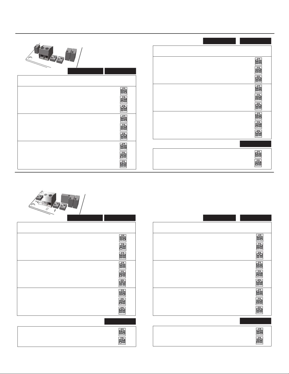
Figure 5 - Switch Selections for Low Pressure Transducers with mA Outputs
Zb
+ -
Range Configuration:
R1/R5 0 - 0.10 "wc / 25 pa
R2/R6 0 - 1.0 "wc / 250 pa (default)
R3/R7 0 - 5.0 "wc / 1250 pa (default)
R4/R8 0 - 30.0 "wc / 7500 pa (default)
ON
ON
1
2
1
2
S2
Zu S
S1
Uni-Directional
0 - 0.5 "wc / 125 pa
0 - 0.25 "wc / 62.5 pa
0 - 2.5 "wc / 625 pa
0 - 1.25 "wc / 312.5 pa
0 - 15.0 "wc / 3750 pa
0 - 7.5 "wc / 1875 pa
mA Output
Switch 1 (S1)
Factory
Sealed
O N
1
2
O N
1
2
O N
2
1
2
O N
1
2
O N
1
2
O N
1
2
O N
1
2
O N
1
2
O N
1
2
Range Configuration:
Bi-Directional
R1/R5 +/- 0.05 "wc / 12.5 pa
R2/R6 +/- 0.5 "wc / 125 pa (default)
+/- 0.25 "wc / 62.5 pa
+/- 0.125 "wc / 31.25 pa
R3/R7 +/- 2.5 "wc / 625 pa (default)
+/- 1.25 "wc / 312.5 pa
+/- .625 "wc / 156.25 pa
R4/R8 +/- 15.0 "wc / 3750 pa (default)
+/- 7.5 "wc / 1875 pa
+/- 3.75 "wc / 937.5 pa
Output Configuration:
Uni-directional (default)
Bi-directional
Switch 1 (S1)
Factory
Sealed
O N
1
2
O N
1
2
O N
1
2
O N
1
2
O N
1
2
O N
1
2
O N
1
2
O N
1
2
O N
1
2
Switch 2 (S2)
O N
1
2
O N
1
2
Figure 6 - Switch Selections for Low Pressure Transducers with VDC Outputs
ON
1
2
S3
+ - 0
Range Configuration:
R1/R5 0 - 0.10 "wc / 25 pa
R2/R6 0 - 1.0 "wc / 250 pa (default)
0 - 0.5 "wc / 125 pa
0 - 0.25 "wc / 62.5 pa
R3/R7 0 - 5.0 "wc / 1250 pa (default)
0 - 2.5 "wc / 625 pa
0 - 1.25 "wc / 312.5 pa
R4/R8 0 - 30.0 "wc / 7500 pa (default)
0 - 15.0 "wc / 3750 pa
0 - 7.5 "wc / 1875 pa
S1
Zb
ON
ON
1
2
1
2
Zu S
S2
Uni-Directional
VDC Output
Switch 1 (S1)
Factory
Sealed
O N
1
2
O N
1
2
O N
1
2
O N
1
2
O N
1
2
O N
1
2
O N
1
2
O N
1
2
O N
1
2
Range Configuration:
Bi-Directional
R1/R5 +/- 0.05 "wc / 12.5 pa
R2/R6 +/- 0.5 "wc / 125 pa (default)
+/- 0.25 "wc / 62.5 pa
+/- 0.125 "wc / 31.25 pa
R3/R7 +/- 2.5 "wc / 625 pa (default)
+/- 1.25 "wc / 312.5 pa
+/- .625 "wc / 156.25 pa
R4/R8 +/- 15.0 "wc / 3750 pa (default)
+/- 7.5 "wc / 1875 pa
+/- 3.75 "wc / 937.5 pa
Switch 1 (S1)
Factory
Sealed
O N
1
2
O N
1
2
O N
1
2
O N
1
2
O N
1
2
O N
1
2
O N
1
2
O N
1
2
O N
1
2
Output Configuration:
Uni-directional (default)
Bi-directional
Switch 2 (S2)
O N
1
2
O N
1
2
Output Configuration:
0 - 10 (default)
0 - 5 VDC
Switch 3 (S3)
O N
1
2
O N
1
2
Page 4
Page 4 of 4
PX274/275/277/278 Series
LOW PRESSURE SENSORS
CHECKOUT
1. Verify that the unit is mounted in the correct position.
2. Verify appropriate input signal and supply voltage.
Caution: Never connect 120 VAC to these transducers. Never
connect AC voltage to a unit intended for DC supply.
3. Verify appropriate configuration range.
Transducer
This is a rough functional check only.
Operation
1. Adjust the pressure to obtain maximum output signal for
appropriate range.
2. Output should be 20 mA or 5 or 10 VDC.
3. Adjust the pressure to obtain minimum output signal.
4. Output should be 4 mA or 0 VDC.
NOTE: The PX274/275/277/278 is a highly accurate device.
For applications requiring a high degree of accuracy, the use
of laboratory quality meters and gauges are recommended.
CALIBRATION
All units are factory calibrated to meet or exceed published
specifications. If field adjustment is necessary, follow the
instructions below.
Calibration of PX274/275/277/278 mA Units
1. Connect terminals [+] and [-] to the appropriate power
source.
2. Connect the DVM in series on the [-] terminal.
3. Apply low pressure to the unit. If configured for
uni-direction, adjust Zu trimmer to achieve desired low
output. If configured for bi-direction, adjust Zb trimmer to
achieve desired low output.
4. Apply high pressure to the unit and adjust span trimmer [S]
to obtain the desired high output pressure.
5. Repeat steps 3 and 4 until desired calibration is achieved.
Calibration of PX274/275/277/278 VDC Units
1. Connect terminals [+] and [-] to the appropriate power
source. The [-] terminal is also the negative output terminal.
2. Connect the DVM on DC volts across [O] and [-] terminal.
3. Apply low pressure to the unit. If configured for
uni-direction, adjust Zu trimmer to achieve desired low
output. If configured for bi-direction, adjust Zb trimmer to
achieve desired low output.
4. Apply high pressure to the unit and adjust span trimmer [S]
to obtain the desired high output pressure.
5. Repeat steps 3 and 4 until desired calibration is achieved.
MAINTENANCE
FIELD REPAIR
U.S.A.: Omega Engineering, Inc., One Omega Drive, P.O. Box 4047
The information contained in this document is believed to be correct, but OMEGA accepts no liability for any
errors it contains and reserves the right to alter specifications without notice.
Regular maintenance of the total system is recommended to
assure sustained optimum performance.
None. Replace with a functional unit.
omega.com [email protected]
Servicing North America:
Stamford, CT 06907-0047 USA
Toll-Free: 1-800-826-6342 (USA & Canada only)
Customer Service: 1-800-622-2378 (USA & Canada only)
Engineering Service: 1-800-872-9436 (USA & Canada only)
Tel: (203) 359-1660 Fax: (203) 359-7700
e-mail: [email protected]
For Other Locations Visit omega.com/worldwide
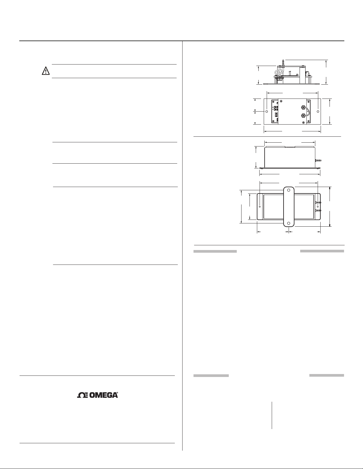
Figure 7 - PX274/275/277/278 Low Pressure Transducer Dimensions shown in
millimeters and (inches).
MAMAC
9280
54
(2.12)
(2.25)
(4.00)
57
102
Enclosure
83
(3.25)
63.5
(2.50)
(1.56)
28
(1.12)
28
(1.12)
56
(2.20)
40
114 (4.50)
Zb
S1 S2
ON
ON
Z
S
127 (5.00)
127 (5.00)
152 (6.00)
140 (5.50)
76 (3.00)76 (3.00)
For Technical / Application Assistance call your nearest office
OMEGA ENGINEERING, INC. warrants this unit to be free of defects in materials and workmanshipfor a
period of 13 months from date of puchase. OMEGA’s WARRANTY adds an additional one (1) month
graceperiod to the normal one (1) year product warranty to cover handling and shipping time. This ensures
that OMEGA’s customers receive maximum coverage on each product.
If the unit malfunctions, it must be returned to the factory for evaluation. OMEGA’s Customer Service
Department will issue an Authorized Return (AR) number immediately upon phone or written request. Upon
examination by OMEGA, if the unit is found to be defective, it will be repaired or replaced at no charge.
OMEGA’s WARRANTY does not apply to defects resulting from any action of the purchaser, including but not
limited to mishandling, improper interfacing, operation outside of design limits, improper repair, or
unauthorized modification. This WARRANTY is VOID if the unit shows evidence of having been tampered
with or shows evidence of having been damaged as a result of excessive corrosion; or current, heat, moisture
or vibration; improper specification; misapplication; misuse or other operating conditions outside of
OMEGA’s control. Components in which wear is not warranted, include but are not limited to contact points,
fuses, and triacs.
OMEGA is pleased to offer suggestions on the use of its various products. However, OMEGA
neither assumes responsibility for any omissions or errors nor assumes liability for any damages
that result from the use of its products in accordance with information provided by OMEGA,
either verbal or written. OMEGA warrants only that the parts manufactured by the company will
be as specified and free of defects. OMEGA MAKES NO OTHER WARRANTIES OR REPRESENTATIONS OF ANY KIND WHATSOEVER, EXPRESSED OR IMPLIED, EXCEPT THAT OF TITLE, AND ALL
IMPLIED WARRANTIES INCLUDING ANY WARRANTY OF MERCHANTABILITY AND FITNESS FOR
A PARTICULAR PURPOSE ARE HEREBY DISCLAIMED. LIMITATION OF LIABILITY: The remedies of
purchaser set forth herein are exclusive, and the total liability of OMEGA with respect to this
order, whether based on contract, warranty, negligence, indemnification, strict liability or
otherwise, shall not exceed the purchase price of the component upon which liability is based.
In no event shall OMEGA be liable for consequential, incidental or special damages.
CONDITIONS: Equipment sold by OMEGA is not intended to be used, nor shall it be used: (1) as a “Basic
Component” under 10 CFR 21 (NRC), used in or with any nuclear installation or activity; or (2) in medical
applications or used on humans. Should any Product(s) be used in or with any nuclear installation or activity,
medical application, used on humans, or misused in any way, OMEGA assumes no responsibility as set forth
in our basic WARRANTY/DISCLAIMER language, and, additionally, purchaser will indemnify OMEGA and
hold OMEGA harmless from any liability or damage whatsoever arising out of the use of the Product(s) in
such a manner.
Direct all warranty and repair requests/inquiries to the OMEGA Customer Service Department. BEFORE
RETURNING ANY PRODUCT(S) TO OMEGA, PURCHASER MUST OBTAIN AN AUTHORIZED RETURN (AR)
NUMBER FROM OMEGA’S CUSTOMER SERVICE DEPARTMENT (IN ORDER TO AVOID PROCESSING
DELAYS). The assigned AR number should then be marked on the outside of the return package and on any
correspondence. The purchaser is responsible for shipping charges, freight, insurance and proper packaging
to prevent breakage in transit.
FOR WARRANTY RETURNS, please have the following
information available BEFORE contacting OMEGA:
1. Purchase Order number under which the product
was PURCHASED,
2. Model and serial number of the product under
warranty, and
3. Repair instructions and/or specific problems
relative to the product.
OMEGA’s policy is to make running changes, not model changes, whenever an improvement is possible. This
affords our customers the latest in technology and engineering. OMEGA is a registered trademark of OMEGA
ENGINEERING, INC.
© Copyright 2015 OMEGA ENGINEERING, INC. All rights reserved. This document may not be copied,
photocopied, reproduced, translated, or reduced to any electronic medium or machine-readable form, in whole
or in part, without the prior written consent of OMEGA ENGINEERING, INC.
WARRANTY/DISCLAIMER
RETURN REQUESTS / INQUIRIES
FOR NON-WARRANTY REPAIRS, consult OMEGA
for current repair charges. Have the following
information available BEFORE contacting OMEGA:
1. Purchase Order number to cover the COST of
the repair,
2. Model and serial number of the product, and
3. Repair instructions and/or specific problems
relative to the product.
 Loading...