

Page 1
PVC Body
0
50
100
150
200
250
62
92
122
152
182
212
73
140
32
1/2˝ to 1˝
1-1/4˝ to 2˝
232
40
WORK ING T EMPERATURE (°F)
WORKING PRESSURE (psi)
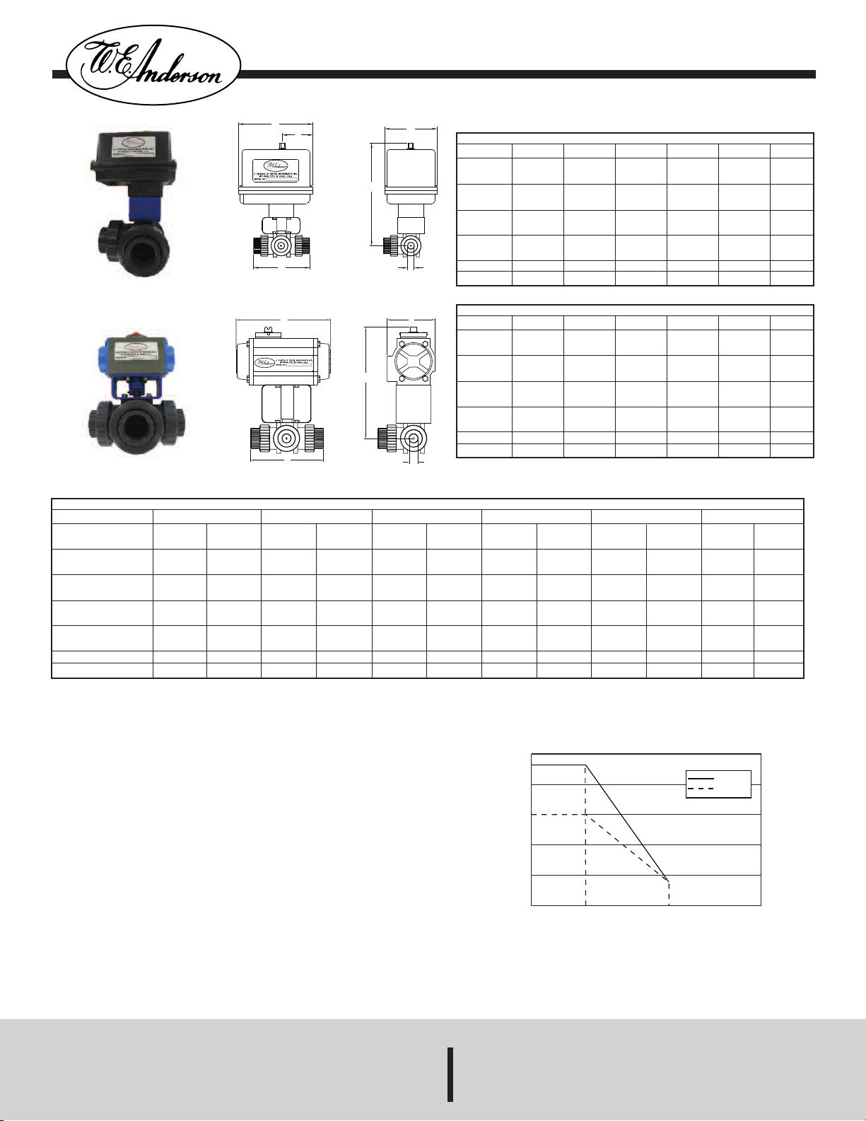
PRESSURE - TEMPERATURE RATINGS
SERIES 3PBV
E
F
D
C
B
A
E
D
C
B
A
¤
PVC Body
C
Series 3PBV Automated Ball Valves - 3-Way Plastic
Specifications - Installation and Operating Instructions
NEUMATIC DOUBLE ACTING – inches/(mm)
P
A
B
C
D
E
ACT.
eight (lb)
W
1/2˝
6-1/32
153.19)
(
-49/64
1
44.85)
(
-1/4
4
(107.95)
4-21/64
(109.93)
A1
D
.47
1
3/4˝
6-15/64
158.35)
(
-49/64
1
44.85)
(
-3/64
5
(128.19)
4-21/64
(109.93)
A1
D
.76
1
1˝
6-25/64
162.32)
(
-49/64
1
44.85)
(
-43/64
5
(144.07)
4-21/64
(109.93)
A1
D
.03
2
PNEUMATIC SPRING RETURN – inches/(mm)
A
B
C
D
E
ACT.
Weight (lb)
1/2˝
-15/32
6
164.31)
(
-51/64
2
(71.04)
4-1/4
107.95)
(
5-1/2
(139.7)
SR2
3.07
3/4˝
-43/64
6
169.47)
(
-51/64
2
(71.04)
5-3/64
128.19)
(
5-1/2
(139.7)
SR2
3.36
1˝
-53/64
6
173.43)
(
-51/64
2
(71.04)
5-43/64
144.07)
(
5-1/2
(139.7)
SR2
3.63
1-1/4˝
6-35/64
166.29)
(
-49/64
1
44.85)
(
-13/16
6
(143.04)
4-21/64
(109.93)
A1
D
.73
2
1-1/4˝
-57/64
6
175.02)
(
-51/64
2
(71.04)
6-13/16
143.04)
(
5-1/2
(139.7)
SR2
4.33
Bulletin V-16
1-1/2˝
7-5/8
193.68)
(
-51/64
2
71.04)
(
-49/64
7
(197.25)
5-1/2
(139.7)
A2
D
.88
4
1-1/2˝
-3/64
8
204.39)
(
-11/64
3
(80.57)
7-49/64
197.25)
(
6-3/8
(161.93)
SR3
6.53
2˝
7-13/16
198.44)
(
-51/64
2
71.04)
(
-59/64
7
(201.22)
5-1/2
(139.7)
A2
D
.38
6
2˝
-1/4
8
209.55)
(
-11/64
3
(80.57)
7-59/64
201.22)
(
6-3/8
(161.93)
SR3
8.03
ELECTRIC ACTUATOR – inches/(mm)
A
B
C
D
E
F
ACT.
Weight (lb)
1/2˝
7-25/32
(197.64)
4
(101.60)
4-1/4
(107.95)
5-5/8
(142.88)
2-5/16
(58.74)
U11
5.42
8-43/64
(220.27)
4-1/4
(107.95)
4-1/4
(107.95)
6-11/16
(169.86)
2-7/16
(61.91)
V12
9.42
3/4˝
7-63/64
(202.80)
4
(101.60)
5-3/64
(128.19)
5-5/8
(142.88)
2-5/16
(58.74)
U11
5.71
8-55/64
(225.03)
4-1/4
(107.95)
5-3/64
(128.19)
6-11/16
(169.86)
2-7/16
(61.91)
V12
9.71
The Series 3PBV is ideal for mixing or diverting services in industrial, chemical,
turf and irrigation, and pool and spa applications, as well as for use with potable
water. The valve features a 3-seat design for efficient automation, reinforced TFE
seats and EPDM seals for longer life, and an all PVC construction for heavyweight
durability at a lightweight cost. Valves also come standard with field selectable NPT
or socket process connections.
The 3PBV is an economical automated valve package with either an electric or
pneumatic actuator. Electrically actuated models are weatherproof, NEMA 4,
powered by standard 115 VAC supply, and are available in either two-position or
proportional control. Two-position actuators use the 115 VAC input to drive each of
the valve ports open or closed, while the modulating actuator accepts a 4 to 20 mA
input for infinite valve positioning. Actuator features include thermal overload
protection to withstand stall conditions, visual position indication and a permanently
lubricated gear train.
The pneumatic double acting actuator uses an air supply to drive each of the
actuator ports. Spring return pneumatic actuators use the air supply to drive the
valve stem one direction, and internally loaded springs return the valve to its
original position. Also available is the SV3 solenoid valve to electrically switch the
supply pressure between the air supply ports. Actuators are constructed of
anodized aluminum and are epoxy coated for years of corrosion free service.
1˝
8-9/64
(206.77)
4
(101.60)
5-43/64
(144.07)
5-5/8
(142.88)
2-5/16
(58.74)
U11
5.98
9-1/64
(229)
4-1/4
(107.95)
5-43/64
(144.07)
6-11/16
(169.86)
2-7/16
(61.91)
V12
9.98
1-1/4˝
8-25/64
(213.12)
4
(101.60)
6-13/16
(173.04)
5-5/8
(142.88)
2-5/16
(58.74)
U11
6.68
9-17/64
(235.35)
4-1/4
(107.95)
6-13/16
(173.04)
6-11/16
(169.86)
2-7/16
(61.91)
V12
10.68
1-1/2˝
8-17/32
(216.69)
4
(101.60)
7-49/64
(197.25)
5-5/8
(142.88)
2-5/16
(58.74)
U11
7.58
9-13/32
(238.92)
4-1/4
(107.95)
7-49/64
(197.25)
6-11/16
(169.86)
2-7/16
(61.91)
V12
11.58
2˝
9-23/32
(246.86)
4-1/4
(107.95)
7-59/64
(201.22)
6-11/16
(169.86)
2-7/16
(61.91)
U12
11.08
9-23/32
(246.86)
4-1/4
(107.95)
7-59/64
(201.22)
6-11/16
(169.86)
2-7/16
(61.91)
V12
13.08
DWYER INSTRUMENTS, INC.
P.O. BOX 358 • MICHIGAN CITY, INDIANA 46360 U.S. A.
Page 2
age 2
P
PECIFICATIONS
S
Service: Compatible liquids or gases.
Body: 3-way.
Line Size: 1/2˝ to 2˝.
nd Connections: Female NPT or socket (field selectable).
E
ressure Limit: 1/2˝ to 1˝: 232 psi (16.0 bar) @ 73°F (23°C); 1-1/4˝ to 2˝: 150 psi
P
10.3 bar) @ 73°F (23°C) WOG. Vacuum: 29˝ Hg. See chart for curve.
(
etted Materials:
W
Body, End Connectors: PVC.
Ball, Stem: PVC.
Seat: TFE.
tem Seal: EPDM.
S
emperature Limit: 32 to 140°F (0 to 60°C).
T
CTUATORS
A
Electric
Power Requirements: 120 VAC, 50/60 Hz, single phase. Optional 220 VAC, 24 VAC,
12 VDC, and 24 VDC.
ower Consumption: (Locked Rotor Current): Two Position: 1/2˝ to 1-1/2˝: .55A, 2˝:
P
.75A. Modulating: 0.75A.
0
ycle Time: (per 90°): Two Position: 1/2˝ to 1-1/2˝: 2.5 sec., 2˝: 5 sec. Modulating: 5
C
sec.
ERIES 3PBV AUTOMATED BALL VALVES - 3-WAY PLASTIC
S
Size
1/2˝
3/4˝
˝
1
-1/4˝
1
1-1/2˝
2˝
*Complete model includes Port Configuration - see below.
CV
ee Chart Below
S
Double Acting Pneumatic
Model*
3PBVPDA102
3PBVPDA103
PBVPDA104
3
PBVPDA105
3
3PBVPDA206
3PBVPDA207
Spring Return Pneumatic
Model*
PBVPSR202
3
PBVPSR203
3
PBVPSR204
3
3PBVPSR205
3PBVPSR306
3PBVPSR307
uty Cycle: Two Position: 1/2˝ to 1-1/2˝: 75%, 2˝: 25%. Modulating: 75%.
D
Enclosure Rating: NEMA 4. Optional NEMA 7 (Class 1, Div. II groups A, B, C, D).
Housing Material: Aluminum with thermal bonding polyester powder finish.
Temperature Limit: 0 to 150°F (-18 to 65°C).
onduit Connection: 1/2˝ female NPT.
C
odulating Input: 4 to 20 mA.
M
tandard Features: Manual override and visual position indicator except modulating
S
nits.
u
Pneumatic “DA” and “SR” Series
Type: DA series is double acting and SR series is spring return (rack and pinion).
ormal Supply Pressure: 80 psi (5.5 bar).
N
aximum Supply Pressure: 120 psig (8 bar).
M
ir Connections: 1/4˝ female NPT.
A
ir Consumption (per stroke): DA1: 2.32 cu. in.; DA2, SR2: 9.34 cu. in.; SR3: 17.21
A
cu. in.
Cycle Time (per 90°): DA1: .03 sec.; DA2: .04 sec.; SR2: .09 sec.; SR3: .14 sec.
Housing Material: Anodized aluminum body and epoxy coated aluminum end caps.
emperature Limit: -4 to 180°F (-20 to 82°C).
T
ccessory Mounting: NAMUR standard.
A
tandard Features: Visual position indicator.
S
Two Position Electric
Model*
3PBVPU1102
3PBVPU1103
PBVPU1104
3
PBVPU1105
3
3PBVPU1106
3PBVPU1207
Modulating Electric
Model*
3PBVPV1202
3PBVPV1203
PBVPV1204
3
PBVPV1205
3
3PBVPV1206
3PBVPV1207
-T1
-T2
-T3
-T4
-L1
-L2
-L3
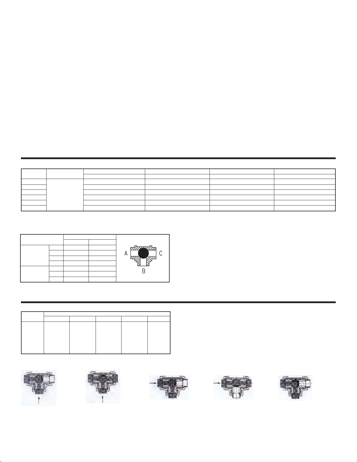
Flow Path
Act. Open
All Open
A-B
A-C
B-C
B-C
A-B
All Closed
Port
Configuration
“T” Port
“L” Port
Example: 3PBVPSR204-L3
Cv Values
Position
Size
1/2˝
3/4˝
1˝
1-1/4˝
1-1/2˝
2˝
A
3.85
9.50
14.4
27.3
33.3
63.0
B
2.45
6.65
9.80
18.9
23.1
43.4
Act. Closed
A-B
A-C
B-C
All Open
A-B
All Closed
B-C
C
4.55
10.2
17.2
32.2
42.0
84.0
D
13.7
26.6
53.2
73.5
119
224
E
5.11
10.5
18.6
33.3
43.4
85.4
Position A:
• T-Port
• Center Inlet
• Diverting Flow
Position B:
• T-Port
• Center Inlet
• Separating Flow
Position C:
• T-Port
• Side Inlet
• Diverting Flow
Position D:
• T-Port
• Side Inlet
• Straight Flow
Position E:
• L-Port
• Any Inlet
• Diverting Flow
Page 3

LECTRIC ACTUATOR
E
. BASIC INSTALLATION
I
. Operate valve manually and place in the open position. (NOTE: ALL ELECTRIC
1
CTUATORS ARE SHIPPED IN THE OPEN POSITION.)
A
2. Remove any mechanical stops the valve might have. (DO NOT REMOVE ANY
PARTS NECESSARY FOR THE PROPER OPERATION OF THE VALVE, SUCH
AS THE PACKING GLAND, PACKING NUT, ETC.)
. Ensure that the actuator output shaft and valve stem are aligned properly. If they
3
re not, operate the valve manually until they are correct.
a
. Mount actuator to valve. Do not tighten nuts and bolts at this time.
4
. Remove actuator cover.
5
6. Bring power to the actuator. CAUTION: Make sure power is OFF at the main
box.
7. Wire the actuator per the diagram attached to the inside of the cover. Special
ctuators (those with positioner boards, etc.) will have diagrams enclosed inside
a
he cover.
t
. Securely tighten bolts used to mount the actuator to a mounting bracket or
8
directly to the valve mounting pad if it is ISO5211 compliant.
9. Cycle the unit several times and check the open and closed positions of the
valve. Cams are pre-adjusted at the factory; due to the variety of valve designs and
types, however, slight adjustments might be required. (SEE II and III).
0. Replace cover and tighten screws.
1
I. TO SET THE OPEN POSITION
I
1. Cycle the valve to the open position by applying power to terminals #1 and #2.
The top cam and switch control this position. In the open position, the set screw in
the top cam will be accessible.
2. If the valve is not open completely:
. Slightly loosen the 8-32 x 1/4” set screw on the top cam.
A
. Rotate the cam clockwise (CW) by hand until the switch makes
B
ontact. Contact is made when a slight click can be heard. By making
c
incremental CW movements of the top cam, the valve can be
positioned precisely in the desired position.
C. When the top cam is set, tighten the set screw securely.
3. If the valve opens too far:
A. Apply power to terminals #1 and #3. This will begin to rotate valve
CW. When valve is full open and in the exact position desired,
remove power from actuator.
B. Loosen the set screw in the top cam.
C. Rotate the top cam counterclockwise (CCW) until the switch arm
drops off the round portion of the cam onto the flat section. A slight
click can be heard as the switch changes state.
D. Continue applying power to terminals #1 and #3 until valve is in the
desired position.
III. TO SET THE CLOSED POSITION
1. Apply power to terminals #1 and #3 to move the valve toward the closed position.
The bottom cam and switch control the closed position. In the closed position, the
set screw in the bottom cam will be accessible.
2. If the valve is not closed completely:
A. Slightly loosen the 8-32 x 1/4” set screw on the bottom cam.
B. Rotate the cam counter-clockwise (CCW) by hand until the switch
makes contact. Contact is made when a slight click can be heard. By
making incremental CCW movements of the bottom cam, the valve can
be positioned precisely in the desired position.
C. When the top cam is set, tighten the set screw securely.
3. If the valve closes too far:
A. Apply power to terminals #1 and #2. This will begin to rotate valve
CCW. When valve is fully closed and in the exact position desired,
remove power from actuator.
B. Loosen the set screw in the top cam.
C. Rotate the top cam clockwise (CW) until the switch arm drops off the
round portion of the cam onto the flat section. A slight click can be
heard as the switch is no longer making contact with the round part of
the cam.
D. Continue applying power to terminals #1 and #2 until valve is in the
desired position.
IV. MAINTENANCE
Once the actuator has been properly installed, it requires no maintenance. The
gear train has been permanently lubricated and in most cases will never be
disturbed. In the event it becomes necessary to open the gear box for any reason,
however, Shell Darina
®
#2 grease is recommended for re-lubricating.
age 3
P
. DUTY CYCLE
V
ost standard electric actuators are rated for 25% duty cycle at 100% ambient
M
emperature at the rated torque.
t
VI. THERMAL OVERLOAD
All actuators are equipped with thermal overload protection to guard the motor
against damage due to overheating.
II. MECHANICAL OVERLOAD
V
ll actuators are designed to withstand stall conditions. It is not recommended to
A
ubject the unit to repeated stall conditions.
s
VIII. SPARE PARTS
When ordering parts, please specify:
. Model # B. Serial # C. Part Description
A
ecommended spare parts include:
R
A. Standard actuator: set of cams and switches.
B. Actuators w/positioner: set of cams and switches; 1K potentiometer; valve
positioner board.
X. NEMA 7 ELECTRIC ACTUATORS
I
n general, operation and maintenance of a NEMA 7 electric actuator is no different
I
hat of a NEMA 4 actuator. However, some precautions must be followed:
t
1. DO NOT under any circumstances remove the cover of the actuator while in a
hazardous location. Removal of the cover while in a hazardous location could
cause ignition of hazardous atmospheres.
2. DO NOT under any circumstances use a NEMA 7 electric actuator in a
azardous location that does not meet the specifications for which the actuator was
h
esigned.
d
. Always mount and cycle test the actuator on the valve in a non-hazardous
3
location.
4. When removing the cover, care must be taken not to scratch, scar of deform the
flame path of the cover and base of the actuator, since this will negate the NEMA
rating of the enclosure.
5. When replacing the cover on actuators rated for both NEMA 4 & 7, take care that
the gasket is in place to assure proper clearance after the cover is secured. After
the cover screws are tightened, the clearance between the cover and the base
should be checked. A .002” thick by 1/2” wide feeler gauge is used for this; it must
not enter between the two mating faces more than .125".
6. All electrical connections must be in accordance with the specifications for which
the unit is being used.
7. Should the unit ever require maintenance, remove from the hazardous location
before attempting to work on the unit. If the actuator is in a critical application, it is
advisable to have a standby unit in stock.
XI. TROUBLESHOOTING
SYMPTOM
Actuator does not
respond to
control signal
PROBLEM
•Power is not on
•Actuator wired incorrectly
•Incorrect voltage
SOLUTION
•Turn on Power
•Check wiring diagram;
re-wire
•Bring correct supply to
actuator
•Thermal Overload
•Allow motor to cool; resets
automatically
•Actuator and Valve in
opposite positions when
•Remove actuator; remount
after 90° turn
actuator installed
Actuator will not
open and/or close
completely
•Travel limit switch set
incorrectly
•Valve torque too high
•Mechanical stops not
•Set cams per instructions
•Install correct unit
•Remove stops
removed when installing
actuator
Valve oscillates
•Torque of valve too high
•Actuator without brake
•Torque of valve too high
•Install brake
installed on butterfly valve
Actuator motor
•Motor brake misadjusted
•Gear damaged/sheared pin
•Adjust brake; tighten screw
•Contact factory
runs but output
shaft does not
rotate
Darina® is a registered trademark of Shell Oil Company
Page 4
Page 4
NEUMATIC ACTUATOR
P
OTE: For optimal operation, 3PBV actuators should be run with a supply of clean,
N
ubricated air.
l
SPRING RETURN ACTUATORS
Air to PORT 2 (the right hand port) causes the actuator to turn CCW. Loss of air to
PORT 2 causes air to exhaust and the actuator turns CW. This is the FAIL CLOSE
peration.
o
OUBLE ACTING ACTUATORS
D
ir to PORT 2 (the right hand port) causes the actuator to turn CCW. Air to PORT
A
(the left hand port) causes the actuator to turn CW.
1
DISASSEMBLING STANDARD ACTUATORS
IMPORTANT: Before beginning disassembly, ensure that the air supply to the
ctuator has been disconnected, all accessories have been removed and that the
a
ctuator has been dismounted from the valve.
a
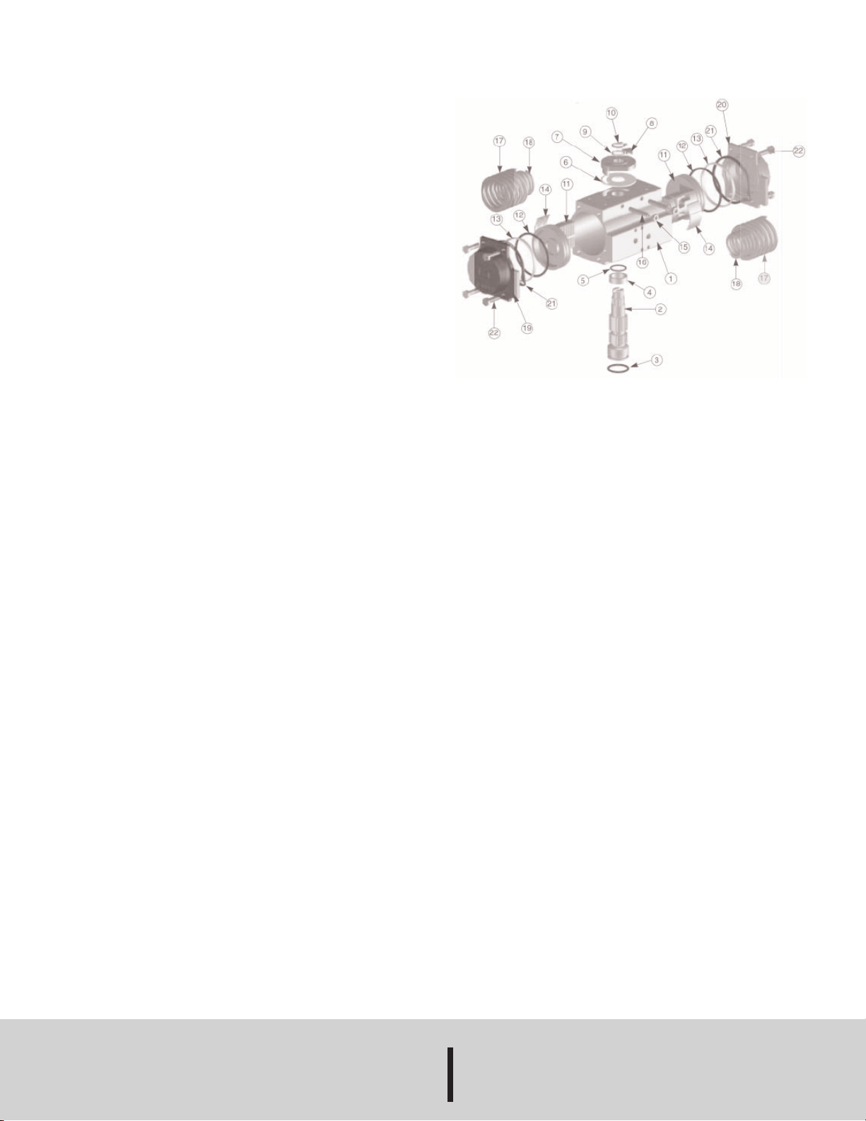
. Loosen the end cap fasteners (22) with a wrench (size varies depending on
1
actuator model). On the spring return actuator, alternate 3 to 5 turns on each
fastener until the springs are completely decompressed. Use caution in removing
the cap since the springs are under load until the fasteners are fully extended.
2. Remove the pinion snap ring (10) with a lock ring tool. The indicator (7) may now
e removed.
b
. Turn the pinion shaft (2) CCW until the pistons are at the full end of travel.
3
isengage the pistons (11) from the pinion. (NOTE: Low pressure air--3 to 5 P.S.I.
D
MAXIMUM--might be required to force the pistons completely from the body.) Note
the position of the pistons before removing them from the actuator body. The part
umbers of the pistons are located on the side and should be right-side up on an
n
actuator with a standard orientation.
4. Remove the pinion through the bottom of the actuator. The actuator is now
completely disassembled. All replacement parts may now be put in. W.E. Anderson
recommends that all wear parts (3, 4, 5, 6, 12, 13, 14) be replaced before
eassembly.
r
REASSEMBLING STANDARD ACTUATORS
IMPORTANT: Be sure that the actuator surfaces are free of grit and scratches
before reassembling.
1. Apply a light film of grease to all o-rings and the pinion before replacing.
2. Put the pinion (2) back through the actuator with the flats of the pinion shaft
running parallel with the body.
3. When reassembling the actuator, make sure that the piston racks are square to
the actuator body and returned to their original orientation. (NOTE: The normal
operation of all PBV pneumatic actuators is FAIL CLOSED. To change the
orientation to FAIL OPEN, rotate the racks 180º to create a reverse operation.)
4. When replacing springs in a spring return actuator, ensure that the springs are
replaced in their identical position in the end cap from which they were removed.
(NOTE: In some circumstances, you might want to change the standard 80 pound
spring set to fit your application and available air pressure. Changing the spring
sets on 3PBV pneumatic actuators requires no special tools. Please refer to the
spring combination torque chart in our catalog for the inner and outer spring
combinations that will allow you to operate with the spring set that you desire.)
4. Seal the end caps with a petroleum lubricant and bolt to actuator body.
5. Check the seal of the actuator by covering seal areas (pinion, end caps) with
soapy water and using low pressure air to the actuator to ensure that no bubbles
are produced.
NEUMATIC ACTUATOR PARTS LIST
P
. Extruded aluminum housing
1
2. Nickel plated steel anti-blowout pinion
3. NBR 70 lower pinion O-ring
4. PTFE pinion spacer ring
5. NBR 70 top pinion O-ring
. PTFE cam spacer ring
6
◊
◊
◊
◊
7. SS indicator cam
8. Nylon position indicator
9. SS pinion washer
10. Pinion snap ring
11. Die cast aluminum piston
12. Piston O-ring bushing
◊
3. PTFE antifriction ring
1
14. PTFE piston thrust block
15. SS stop bolt retaining nut
16. SS stop bolt
17. External spring*
8. Internal spring*
1
19. Die cast aluminum end cap (left)
20. Die cast aluminum end cap (right)
21. NBR end cap seats
22. SS end cap bolt
◊
◊
*Spring return actuators only parts subject to wear. Please contact the factory or
your W.E. Anderson distributor for replacement kits.
MAINTENANCE
The Series 3PBV Automated Ball Valves are not field serviceable and should be
returned if repair is needed (field repair should not be attempted and may void
warranty). Be sure to include a brief description of the problem plus any relevant
application notes. Contact customer service to receive a return goods authorization
number before shipping.
©Copyright 2014 Dwyer Instruments, Inc. Printed in U.S.A. 9/14 FR# RV-443423-00 Rev. 1
DWYER INSTRUMENTS, INC.
P.O. BOX 358 • MICHIGAN CITY, INDIANA 46360 U.S. A.
 Loading...