

Page 1
PTC-14-A
Multifunction Digital Timer
Page 2

omega.com [email protected]
Omega Engineering, Inc:
800 Connecticut Ave. Suite 5N01, Norwalk, CT 06854, USA
Toll-Free: 1-800-826-6342 (USA & Canada only)
Customer Service: 1-800-622-2378 (USA & Canada only)
Engineering Service: 1-800-872-9436 (USA & Canada only)
Tel: (203) 359-1660
e-mail: [email protected]
Omega Engineering,
Limited:
1 Omega Drive, Northbank,
Irlam Manchester M44 5BD
United Kingdom
Omega Engineering,
Daimlerstrasse 26 75392
Deckenpfronn Germany
Fax: (203) 359-7700
GmbH:
Page 2
Page 3
Please read this document carefully before using this product. The product guarantee will become invalidated by any damage to the timer
caused by not following the instructions in the user manual. Omega do not accept any liability for personal injury, material damage or capital
losses which may arise by not following the instructions in the user manual.
• 4 digit red LED display panel mounting digital timer
• 5 programmable timing modes
• Time ranges from 0-99.99sec to 0-9999hrs
• 24Vac/dc or 100-240Vac powered
• 1 changeover and 1 N/O relay output
• Programmable reset function
• Easy to programme through front keys
• Status and timing indicators
• Selectable up/down timing
• EEPROM memory (minimum 10 years)
• Security passcode
• IP65 enclosure
TECHNICAL SPECIFICATION
ENVIRONMENTAL CONDITIONS
Operating/Storage Temperature: 0ºC to +50ºC / -20ºC to +60ºC
Protection Class: IP65
Maximum Installation Height: 2000m
Do not use this timer in locations where corrosive or flammable gases could be present.
ELECTRICAL
Power Supply Voltage: 24Vac/dc or 100-240Vac
Power Consumption (Burden): <3VA
Frequency 50/60Hz
Wiring: 2mm² screw type terminals
Data Retention: EEPROM (minimum 10 years)
CE Markings: Directive LV 2014/35/EU (EN 60730-1, EN 60730-2-7, EN 61812-1, UL 508)
Directive EMC 2014/30/EU (EN 55011: class B; EN 61000-4-2,
EN 61000-4-3, EN 61000-4-4, EN 61000-4-5, EN 61000-4-6)
OUTPUTS
Relay Outputs (R1 & R2): Out1: Single pole changeover contact 16A rated at 240Vac (resistive load)Single pole changeover contact 16A rated at 240Vac (resistive load)
Out2: Single pole N/O contact 5A rated at 240Vac (resistive load)Single pole N/O contact 5A rated at 240Vac (resistive load)
Relay Contact Life: Mechanical 1,000,000 operations
Electrical 100,000 operations
Reset Time: 100ms approx.
Accuracy: ±3sec/24hours
HOUSING
Housing Type: Panel mounting
Display: 4 digit red LED display
Dimensions: 78mm wide x 35mm high x 64mm deep
Weight: Approximately 130g (without packaging)
Enclosure Materials: Self extinguishing plastics, UL 94 V0
When cleaning the timer, solvents (thinners, gasoline, acid etc.) or corrosive materials must not be used.
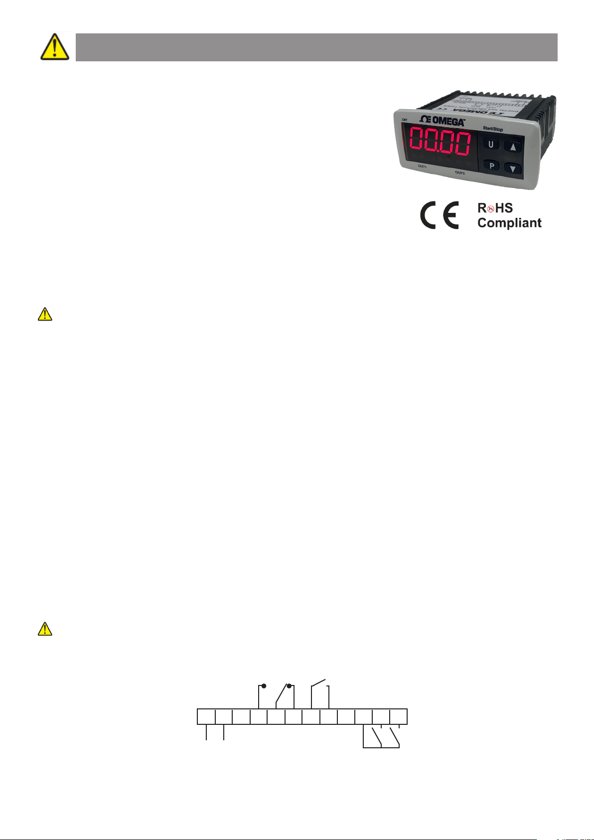
WIRING CONNECTIONS
OUT1
OUT2
INPUTS
21 43 5
(+)
(-)
~
~
SUPPLY
6
7 8 9 10 11 12
Page 3
RST CNT
Page 4
FRONT PANEL DISPLAY FUNCTIONS
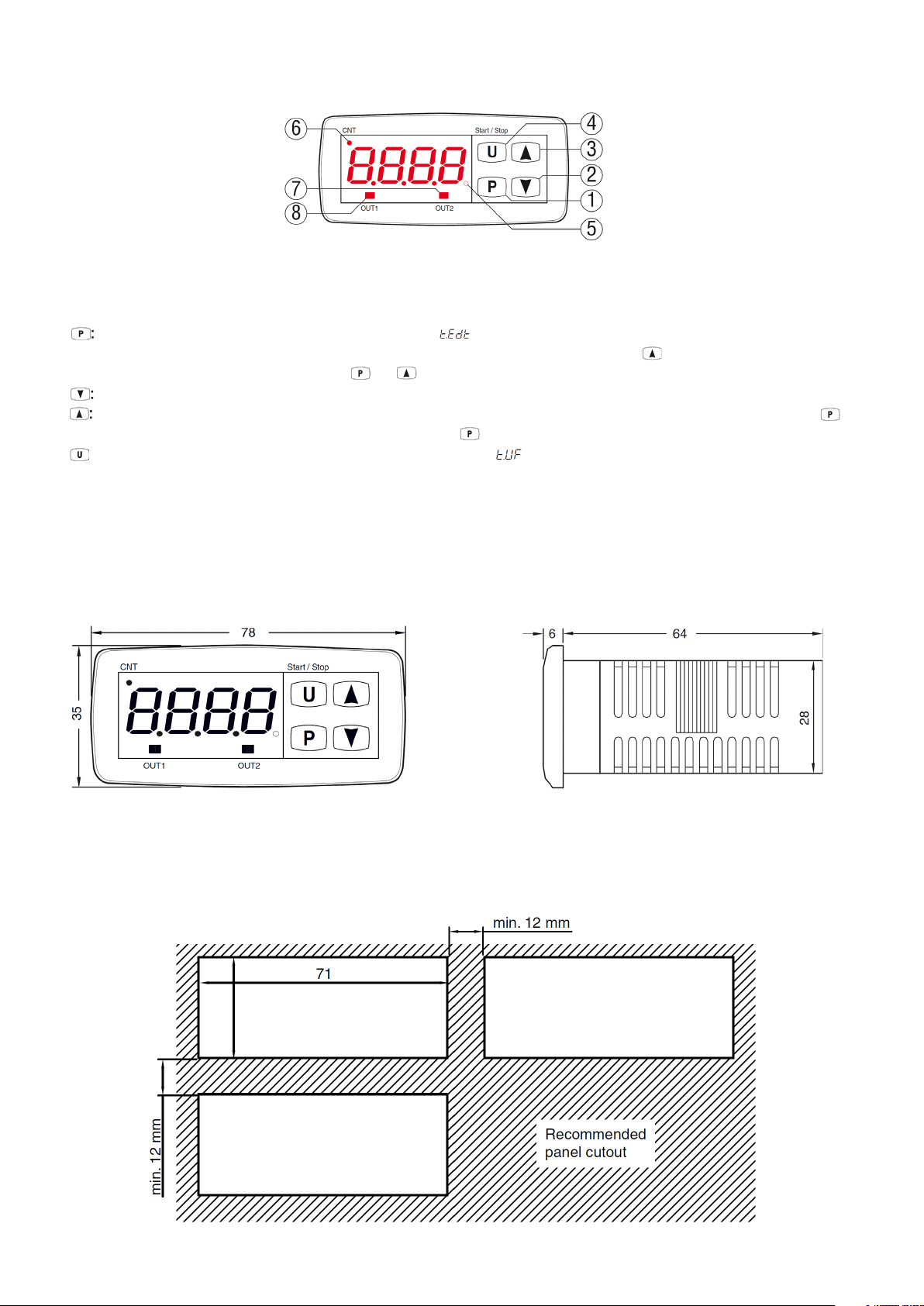
KEYS & DISPLAY SYMBOLS
1. Press and release to set the time delays (if programmed with the parameter). Press for 5 seconds to enter the programming mode. Press
again to access the parameter edit mode and confirm the values. In programming mode press together with the key to change the programming level
of the parameters. When the keys are locked press the and keys together for 5 seconds to unlock the keys.
2. When in programming mode, press to decrease the setting value and to select parameters.
3. When in programming mode, press to increase the setting value and to select parameters. In programming mode press together with the key
to change the programming level of the parameters. Press together with the key to unlock the keys.
4. Start/Stop: Press for Start/Stop/Reset functions as programmed using the parameter.
5. SET LED: In normal operating mode this indicates the time delays are being set. In programming mode this indicates the parameter programming level.
6. CNT LED: Indicates count in progress (flashes every 1 second), count interrrupted (steadily on) or the reset status (off).
7. OUT2 LED: Indicates the status of output relay 2 (illuminated for ON and not illuminated for OFF).
8. OUT1 LED: Indicates the status of output relay 1 (illuminated for ON and not illuminated for OFF).
DIMENSIONS
PANEL CUTOUT
All dimensions in mm
mm
29 mm
Page 4
Page 5
SET TIME PROGRAMMING (FAST MODE)
1. To set the delay times (set times) press the key, the SET LED will illuminate and the display will show (parameter acronym) and its
programmed value. To change the value press the key to increase the value shown or the key to decrease it. Note: Press the keys for
longer than 1 second to increase/decrease the numerical value more quickly.
Through programming the parameter it is possible to select which set times can be set in this fast mode. An option also exists which allows the
setting of the set time value only using the keys without pressing the key in advance ( = 8). The options for the parameter
are as follows:
oF No set time can be set with the short key (if pressed and released the key has no effect).
1 Only set time value can be set with this procedure.
2 Only set time value can be set with this procedure.
3 and set time values can be set with this procedure.
4 Only set time value can be set with this procedure.
5 and set time values can be set with this procedure.
6 and set time values can be set with this procedure.
7 , and set time values can be set with this procedure.
8 set time value can be set directly with the keys.
For example, when the parameter is set to 1 or 3, the procedure is as follows:
- Press and release the key, the display shows alternated with the value.
- To change the set time, press the key to increase the value or the key to decrease the value.
- If = 1, once the desired value has been set, press the key to exit the set time programming mode.
- If = 3, pressing and releasing the key the display shows alternating with the value. To change the value use the keys using the
same method as for the value.
- Once the set time(s) have been programmed, press the key to exit the set time programming mode. If no key is pressed for over 10 seconds the
display will automatically return to normal operation.
x and can be set within the limits established by parameters and and can be set within the limits estblished by and
. .
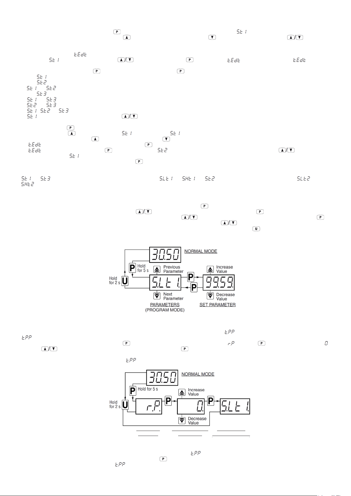
PARAMETER SETTING MODE
To access the timer function parameters when passcode protection is disabled, press the key for 5 seconds, after which the display shows the code
that identifies the first programmable parameter. Use the keys to select the desired parameter then press the key, the display will then show
the parameter code, alternated with its value, that can then be changed with the keys. Once the desired value has been reached, press the
key again to store the new value, the display will then return to show the parameter code. Press the keys to select any other desired parameters
and change them using the same method. To exit the programming mode, press no key for 30 seconds or keep the key pressed for 2 seconds. The
timer display will then return to showing the timing count value.
PARAMETER PROTECTION USING A PASSCODE
The timer has a parameter protection function using a passcode that can be personalised through the parameter. To protect the parameters, set the
x parameter to your desired passcode number.
When the passcode protection is active, press the key for 5 seconds after which the display shows . Press the key and the display will show .
Using the keys, enter the programmed passcode number and press the key again. If the passcode is correct the timer will display the code of
the first programmable parameter and it is possible to program the timer as previously described.
The passcode protection can be disabled by setting = oF.
PASSWORD
REQUEST
INSERT CORRECT
PASSWORD
PARAMETERS
(PROGRAM MODE)
Notes:
1. All parameters are configured by default as protected so that by simply setting the parameter they are all protected by the passcode.
2. If the passcode is lost, switch the timer OFF then ON, pushing the key during initial test and keeping it pressed for 5 seconds. All programmable
parameters are then accessible and parameter can be set as required.
Page 5
Page 6
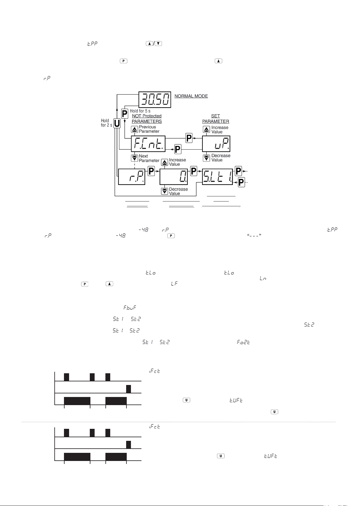
CUSTOMISED PARAMETER PASSCODE PROTECTION
All parameters are configured by default as protected. To make certain parameters programmable without protection whilst keeping the protection on
other parameters, the procedure is as follows:
- Enter program mode using the passcode and with the keys, select the parameter that must be accessible without passcode protection.
- Once the parameter is selected, if the SET LED flashes the parameter is programmable only after entering the passcode (protected).
If the SET LED is steadily ON the parameter is programmable without entering the passcode (unprotected).
- To change the parameter protection, press the key and keeping it pressed, also press the key.
- The SET LED changes its state indicating the new level of parameter protection (ON = unprotected, Flashing = passcode protected).
If some parameters are set as unprotected, when accessing the programming mode the display first shows the unprotected parameters then the
parameter through which it will then be possible to access the protected parameters.
PARAMETERS
PASSWORD
REQUEST
INSERT CORRECT
PASSWORD
GROUP
(PROGRAM MODE)
RESET PARAMETERS TO DEFAULT VALUE
To reset all parameters to the factory default values enter at the passcode request. The passcode must first be enabled by setting parameter
so that the setting is requested. Enter the value and press the key to confirm. The display shows for 2 seconds and then all
parameters have been reset to the factory default values.
KEY LOCK FUNCTION
It is possible to completely lock the timer keys. This function is useful when the timer is being used in an accessible area and unauthorised changes must
be avoided. To activate the key lock, program the parameter to a value different from oF. The value is the time in seconds of key inactivity after
which the keys are automatically locked. When the keys are locked, if any of the keys are pressed the display shows to indicate the key lock is active.
To unlock the keys press the key and key together for 5 seconds, will then appear on the display and all the key functions will be active again.
INTERNAL BUZZER OPERATION
The internal buzzer can be programmed using the parameter to operate as follows:
oF Internal buzzer disabled.
1 The internal buzzer operates at the end of for period. The buzzer also sounds when keys are pressed. If a Reset command is activated (by
a key or digital input), the buzzer is silenced immediately. This buzzer mode is only active for timing operating modes that do not use the time.
2 The internal buzzer operates at the end of for period. The buzzer does not sound when keys are pressed.
3 The buzzer only sounds when keys are pressed.
4 Only the external buzzer output is activated at the end of for period (if OUT2 configured with = 5).
COUNTING OPERATION MODES
CNT
RESET
Count
CNT
RESET
Count
0 1 2 3 4 5 6 7 8 0
Start Stop Start Stop/
0 1 2 3 4 5 0 1 2 3 0
Reset/
Start
Stop
Reset/
Start
Reset
Stop/
Reset
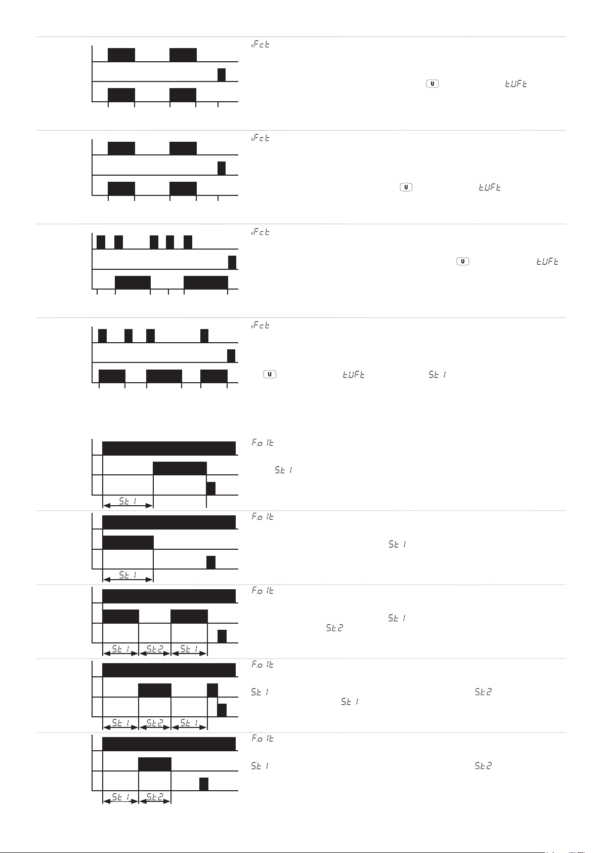
= 1 Bistable Start/Stop
Activating the CNT input starts the timer counting and the CNT input can then be
deactivated. Activating the CNT input again stops the counting on the value reached
(without disabling the output if this was activated). The next CNT impulse resumes the
count from the point it stopped, and so on, until the end of the count or the Reset signal.
In this mode the Start/Stop key (if = 2) acts exactly the same way as the CNT
input with the addition that, when pressed for 2 seconds during the counting, performs the
Reset command. If the counting has finished, pressing the key performs the
Reset-Start command at the same time.
= 2 Bistable Reset-Start/Stop
Activating the CNT input resets and starts the timer counting and the CNT input can then
be deactivated. Activating the CNT input again, if done before the end of the count, stops
the count (disabling the output if this was activated). The next CNT impulse starts a new
count cycle or if the second CNT impulse arrives after the end of the count, a new count
cycle is started. In this mode the Start/Stop key (if = 2) acts exactly the same
way as the CNT input.
Page 6
Page 7
CNT
RESET
Count
0 1 2 3 4 5 6 7 0
Start Stop Start Reset
Stop
= 3 Monostable Start/Stop
Activating the CNT input and keeping it active, starts the timer counting and the count then
stops on the value reached when the CNT input is deactivated (without disabling the output
if this was activated). The next CNT impulse resumes the count from the point it stopped,
and so on, until the Reset signal. In this mode the Start/Stop key (if is different
to oF) only acts as a Reset.
CNT
RESET
Count
CNT
RESET
Count
CNT
RESET
Count
0 1 2 3 0 1 2 3
Reset/
Stop
Start
0 1 2 3 0 0 1 2 3 4 0
0 0
Start
0 1 2 0 0 1 2 3 0
Start Start
Stop/
Reset
Stop
Reset StartReset
OUT1 OPERATING MODES
Start
OUT1
Reset
Reset/
Start
End/
Reset
Stop
0 1 2 0
Start
0
Reset
Stop/
Reset
Stop/
Reset
= 4 Monostable Reset-Start/Stop
Activating the CNT input and keeping it active, resets and starts the timer counting and the
count then stops on the value reached when the CNT input is deactivated (disabling the
output if this was activated). This count operation mode is similar to a traditional timer in
which the counting is enabled when the timer is powered and the Reset occurs when the
power supply is removed. In this mode the Start/Stop key (if is different to oF)
only acts as a Reset.
= 5 Bistable Reset-Start/Stop
Activating the CNT input Resets the timer. Activating the CNT input again starts the timer
counting and activating the CNT input for a third time stops the count on the value reached
(disabling the output if this was activated). In this mode the Start/Stop key (if =
2) acts exactly the same way as the CNT input.
= 6 Bistable Start/Stop-Reset
Activating the CNT input starts the timer counting and the CNT input can then be
deactivated. Activating the CNT input again, if done before the end of the count, stops
the count (disabling the output if this was activated) and Resets the count. If the second
CNT impulse arrives after the end of the count, a new count cycle is started. In this mode
the Start/Stop key (if = 2) at the end of time acts exactly the same way as
the CNT input.
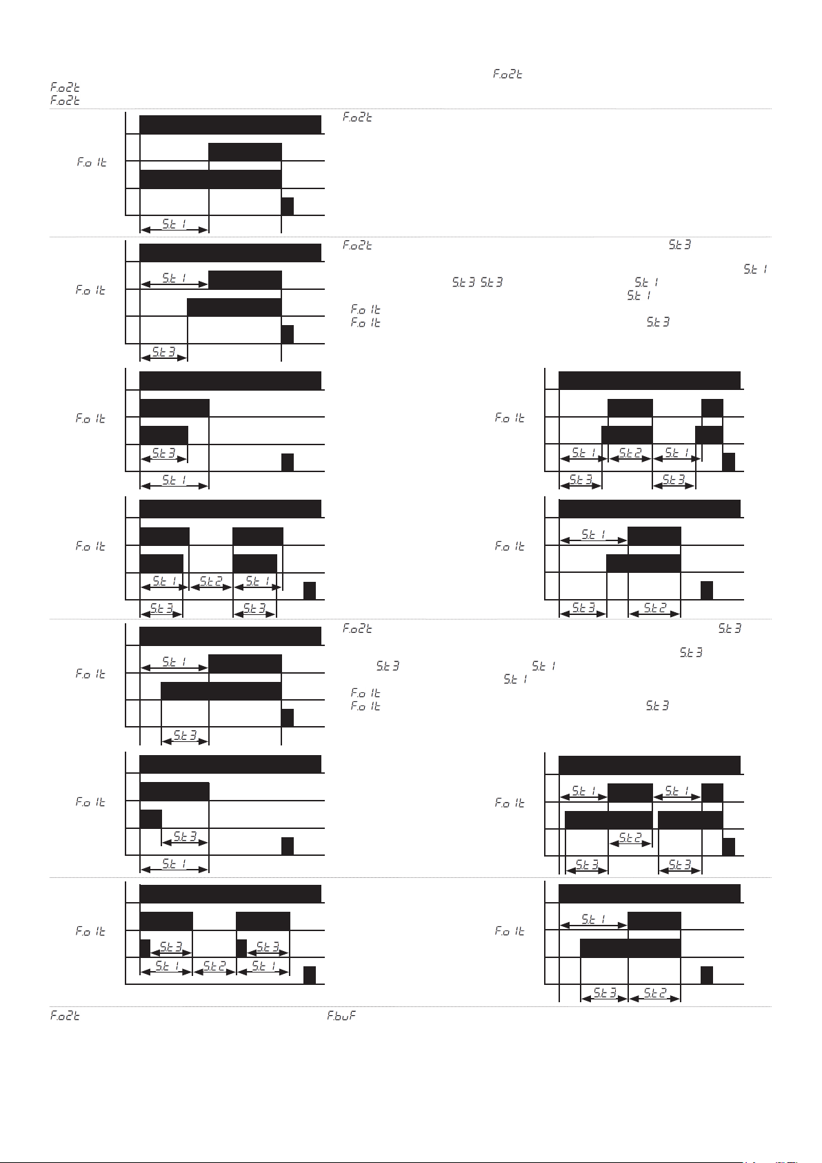
= 1 Delay on Energise (On Delay)
The timer starts counting when the Start signal is activated. At the end of the time
period , the output relay OUT1 energises and remains energised until the Reset signal
is activated.
Start
OUT1
Reset
Start
OUT1
Reset
Start
OUT1
Reset
Start
OUT1
Reset
= 2 Interval
The timer starts counting and the output relay OUT1 energises when the Start signal is
activated. At the end of the time period , the output relay OUT1 de-energises. The
output can only be reactivated after a Reset signal and a new Start signal.
= 3 Immediate Cycle with Variable On and Off Times
The timer starts counting and the output relay OUT1 energises when the Start signal is
activated. At the end of the time period , the output relay OUT1 de-energises and
then after time period OUT1 energises again and this repeats indefinitely until the
Stop/Reset signal is activated.
= 4 Delayed Cycle with Variable On and Off Times
The timer starts counting when the Start signal is activated. At the end of the time period
. the output relay OUT1 energises and then after time period OUT1 de-energises.
After a further time period OUT1 energises again and this repeats indefinitely until the
Stop/Reset signal is activated.
= 5 Single Delayed Cycle with Variable On and Off Times
The timer starts counting when the Start signal is activated. At the end of the time period
. the output relay OUT1 energises and then after time period OUT1 de-energises.
The cycle can only be reactivated after a Reset signal and a new Start signal.
Page 7
Page 8
OUT2 OPERATING MODES
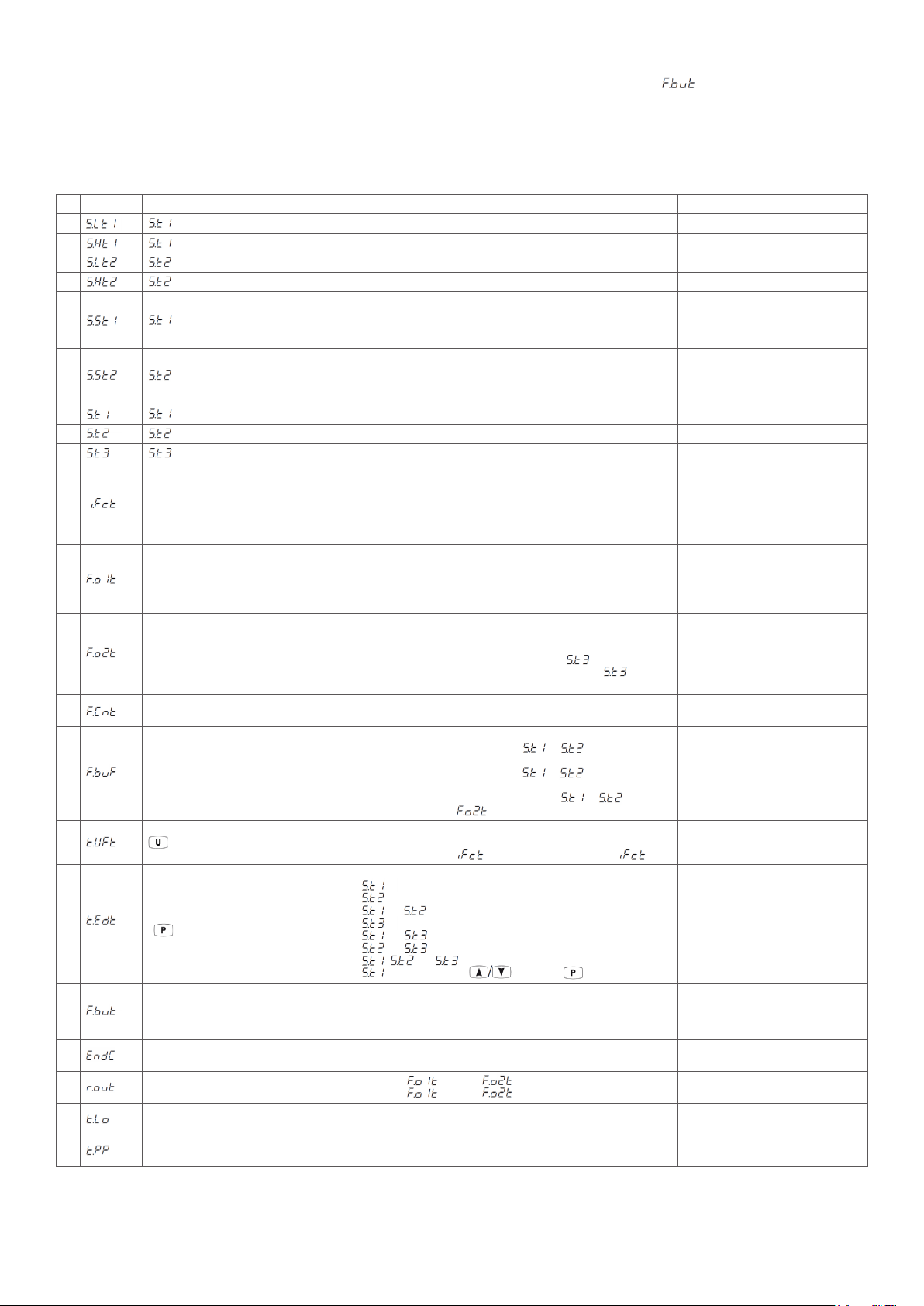
The second output (OUT2) can be programmed in one of 5 different operating modes with the parameter.
. = oF OUT2 disabled
. = 1 OUT2 operates exactly the same as OUT1 to give a double output contact
Start
OUT1
OUT2
Reset
=1
= 2 Instantaneous Contact
OUT2 is energised during the counting process and remains energised until the Reset
signal is activated.
Start
OUT1
OUT2
Reset
Start
OUT1
OUT2
Reset
Start
OUT1
OUT2
Reset
Start
OUT1
OUT2
Reset
= 1
= 2
= 3
= 1
= 3 OUT2 Operates the same function as OUT1 but with time
OUT2 operates exactly the same function as OUT1 but whilst OUT1 operates to time ,
OUT2 operates to time . has the same time range as (9999h, 99h59m,
99m59s or 99.99s) and cannot be set to a value higher than .
If = 1, 4 or 5, OUT2 operates a delay on energise function.
If = 2 or 3, OUT2 operates a feed through function with a set time.
Start
OUT1
= 4
OUT2
Reset
Start
OUT1
= 5
OUT2
Reset
= 4 OUT2 Operates the same function as OUT1 but in advance by time
OUT2 operates exactly the same function as OUT1 but OUT2 operates in advance of
OUT1. has the same time range as (9999h, 99h59m, 99m59s or 99.99s) and
cannot be set to value higher than .
If = 1, 4 or 5, OUT2 operates a delay on energise function.
If = 2 or 3, OUT2 operates a feed through function with a set time.
Start
OUT1
OUT2
Reset
Start
OUT1
OUT2
Reset
= 2
= 3
Start
OUT1
OUT2
Reset
Start
OUT1
OUT2
Reset
= 4
= 5
= 5 OUT2 energises when the buzzer sounds (with = 2) to manage an external sound/light signalling device.
Page 8
Page 9
OPERATION WITH A POWER SUPPLY INTERRUPTION
When the power supply to the timer is restored after an interruption the timing count can be programmed using the parameter to operate as follows:
1 The timing count resets.
2 The timing count stops at the value reached when the power supply ceased. The timing count continues once a new Start signal is activated.
3 The timing count stops at the value reached when the power supply ceased. When the power supply is restored the count restarts from that value if
the conditions for restarting are present (e.g. the timer was counting within a bistable mode when the power supply ceased).
PROGRAMMABLE PARAMETERS
Parameter Description Range Default Note
1 Minimum set time
2 Maximum set time S.Lt1 to 9999 99.59
3 Minimum set time 0 to S.Ht2 0.00
4 Maximum set time S.Lt2 to 9999 99.59
5 Time range
6 Time range
7 Set time S.Lt1 to S.Ht1 1.00
8 Set time S.Lt2 to S.Ht2 0.00
9 Set time S.Lt1 to S.Ht1 0.00
10 CNT input operating mode
11 OUT1 output operating mode
12 OUT2 output operating mode
13 Count mode
14 Buzzer operating mode
15 -START/STOP key operating mode
16
17 Backup operation mode
18 Display to flash at count end
19 Output relay exchange
20 Key lock
21 Passcode for parameters protection
Set times visible with fast set time procedure
( key)
0 to S.Ht1
1 hours (9999h)
2 hours & minutes (99h 59min)
3 minutes & seconds (99min 59s)
4 seconds (99.99s)
1 hours (9999h)
2 hours & minutes (99h59min)
3 minutes & seconds (99min59s)
4 seconds (99.99s)
1 Bistable START/STOP
2 Bistable RESET-START/STOP
3 Monostable START/STOP
4 Monostable RESET-START/STOP
5 Bistable RESET/START/STOP
6 Bistable START/STOP-RESET
1 Delay on Energise (On Delay)
2 Interval
3 Immediate Cycle with Variable On and Off Times
4 Delayed Cycle with Variable On and Off Times
5 Single Delayed Cycle with Variable On and Off Times
oF OUT2 disabled
1 OUT2 operates exactly the same as OUT1
2 Instantaneous contact
3 OUT2 operates the same function as OUT1 but with time
4 OUT2 operates the same function as OUT1 but in advance by time
5 OUT2 energises when the buzzer sounds
uP Up
dn Down
oF Disabled
1 The internal buzzer activates at the end of for period and when
keys are pressed
2 The internal buzzer activates at the end of for period
3 The internal buzzer only activates when keys are pressed
4 Only the external buzzer activates only at the end of for period
(if OUT2 configured with = 5).
oF No function
1 RESET only
2 RESET-START/STOP if = 1/2 or RESET/START/STOP if = 5/6
oF No set time visibility
1
2
3 and
4
5 and
6 and
7 , and
8 only directly with the keys with no key pressed
1 The timing count resets
2 The timing count stops at the value reached when the power supply ceased
3 The timing count stops at the value reached when the power supply ceased
and restarts from that value if the conditions for restarting are present
0 Display flashes at count end
1 Display steadily ON at count end
1-2 Operation on OUT1, on OUT2
2-1 Operation on OUT2, on OUT1
oF Key lock disabled
1 to 9999s (value in seconds of key inactivity after which the keys are locked)
oF Passcode disabled
1 to 9999
0
3
3
2
1
oF
uP
1
2
1
1
0
1-2
oF
oF
Page 9
Page 10
Page 10
Page 11

Page 11
M5784/0323
 Loading...