

Page 1
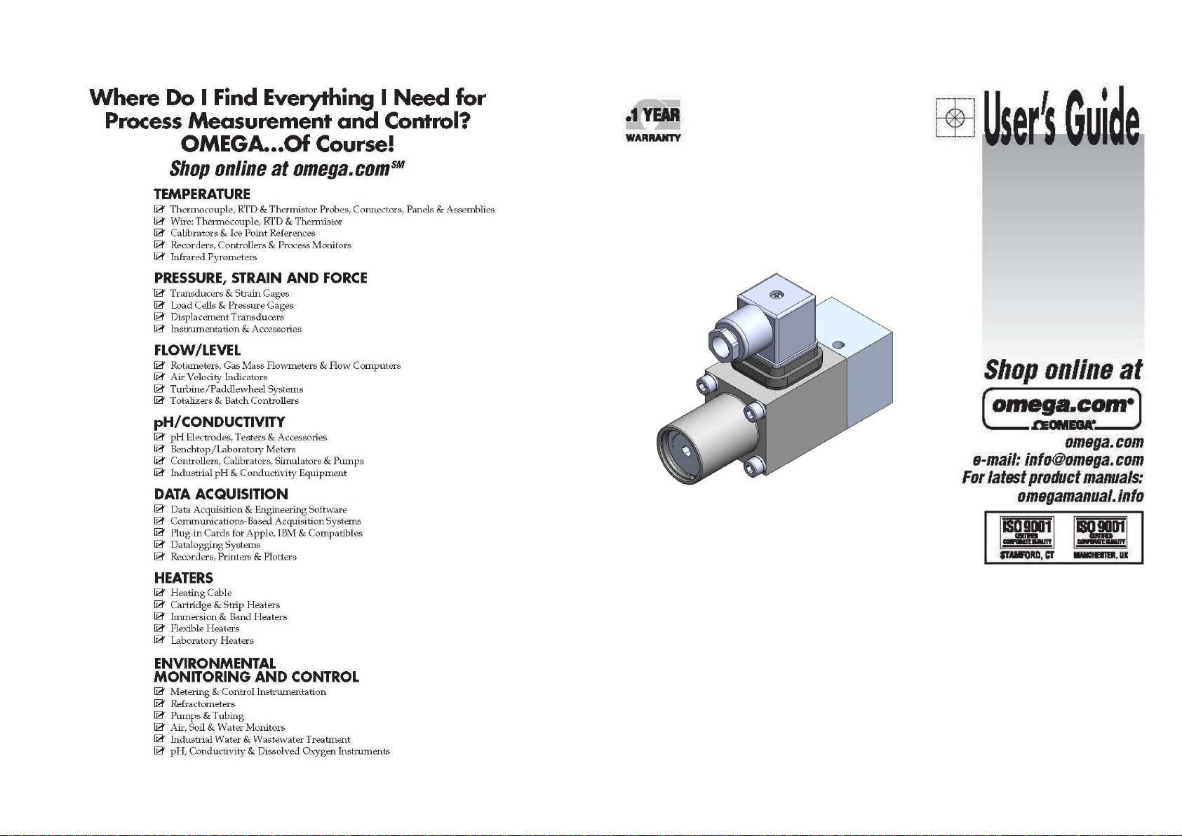
Compact Pressure Switches
PSW8 series
M-5265/0213
Page 2
12
Page 3

NOTES
TABLE OF CONTENTS
Mechanical Pressure Switch PSW8 Series
1 Intended Applications ................................................................................................. 1
2 Safety Instructions ...................................................................................................... 1
3 Standards ..................................................................................................................... 2
4 Transportation and Storage ........................................................................................ 2
5 Installation/Commissioning .................................................................................. 3,4,5
6 Maintenance/Cleaning ................................................................................................. 6
7 Technical Data ............................................................................................................. 7
8 Operation ..................................................................................................................... 8
9 Ordering Code ............................................................................................................. 9
10 Notes ..................................................................................................................... 10,11
11 Warranty / Disclaimer ................................................................................................ 12
i
11
Page 4
1 Mechanical Operations
The pressure switches are specifically applied for monitoring and controlling of operations using
maximum and minimum pressures. A limit switch triggers an electrical signal when minimum or
maximum pressure is reached.
2 Safety Instructions
The safety instructions are intended to protect the user from dangerous situations and/or material
damage.
In the operating instructions the seriousness of a potential risk is designated by the following signal
words:
SAFETY
The pressure switch may be used in the specified fields of application, as long as the pressure,
temperature, and electrical limitations shown on the individual catalogue pages are not
exceeded
Observe also the applicable national safety instructions for assembly, commissioning and
operation of the switch.
The switch is not designed to be used as the only safety relevant element in pressurized systems
according to NEC, ASME, and local regulations .
DANGER
Refers to imminent danger to humans.
Non-observance may result in fatal injuries.
WARNING
Refers to a recognizable danger.
Non-observance may result in fatal injuries, and destroy the equipment or plant parts.
CAUTION
Refers to a danger.
Non-observance may result in light injuries and material damage to the equipment and/or to the
plant.
( Blank Page )
NOTES
1
10
Page 5
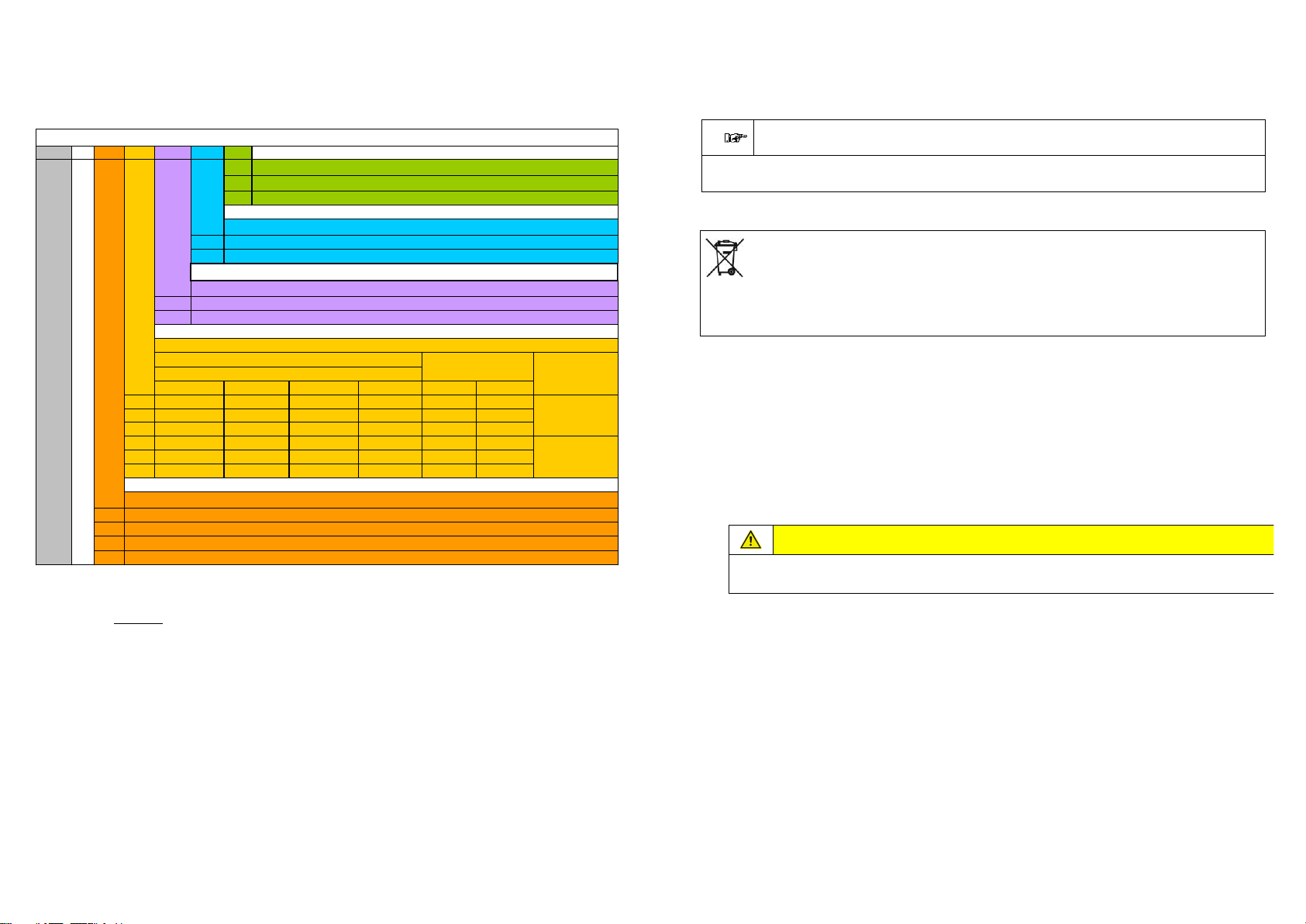
Ordering code with technical information
PSW8 - A A 5 D B
B BUNA-N (NBR)
V
D
M
LIMIT SWITCH
1 GOLD CONTACTS
5 SILVER CONTACTS
PRESSURE RANGE
PSI (bar)
A 1200 (80)
B 1200 (80)
C 1200 (80)
D 8700 (600)
E 8700 (600)
F 13050 (900)
A
C
E
2
OMEGA NUMBER CODING SYSTEM
SEAL MATERIAL
7/16 -20 UNF (SAE-4 O-RING BOSS)
G 1/4" FEMALE
PSI
(5-180)
ELECTRICAL CONNECTION
DIN EN 175301-803 (DIN 43650) SIZE A, 6-8 mm CABLE.
(3.0-41)
(3.0-160)
M12X21 CONNECTOR
VITON (FKM)
(30-300)
INCREASING
PROOF PRESSURE
(bar)
(2.0-17)
(bar)
750-5000
1200-8700
(0.6-6.0)
(3.1-20)
(4.1-45)
8.7-87
45-290
60-650
1/8" NPT FEMALE
PRESSURE CONNECTION
43 - 2320
430 - 4300
800 - 7550
(50-350)
PISTON
(80-600)
1/4" NPT FEMALE
(55-520)
DIAPHRAGM
ADJUSTABLE RANGES
75-2610
PSI
5.8 - 82
29-246
43 - 600
(0.4-5.7)
DECREASING
Example: PSW8-AA5DV : Pressure Switch with ¼ NPT Female, Pressure
Range (5.8 - 87 psi range) [0.4-6.0 Bar] with Viton Material and DIN 43650 - electrical
connection
3
IMPORTANT
Refers to important information essential to the user.
Disposal
The equipment must be disposed correctly in accordance with the local regulations for
electric/electronic equipment.
The equipment must not be disposed of with the household trash
4 Standards
The standards applied during development, manufacture and configuration are listed in the CE
conformity and manufacturer's declaration.
5 Transport/Storage
CAUTION
Severe shock and vibrations should be avoided during transport. Storage should be dry and
clean.
9
2
Page 6
6 Installation/Commissioning
DANGER
Only install or uninstall the switch when de-energized (electrically and hydraulically/pneumatically).
Pressure connection and electrical connection must be carried out by trained or instructed
personnel in accordance with applicable NEC, ASME and local regulations as applicable.
The switch must only be installed in systems where the maximum operation pressure P
max
is not
exceeded (see the name plate).
WARNING
Pressure peaks and pressure shocks exceeding the maximum operating pressure are
inadmissible.
The maximum operating pressure is the upper final value of the operation range or, if specified,
the pressure indicated as maximum operating pressure (see Fig. 9 or the nameplate). Exceeding
the max. operating pressure may affect the performance and the life span of the product and may
cause it to fail prematurely.
IMPORTANT
Check the switch regularly to ensure it functions properly
If the switch does not work properly, stop operation immediately! This switch is non-field
repairable.
IMPORTANT
All pressure switches are 100% tested before they leave the factory. Factory proof pressure is
stated on the nameplate (see Fig.9, page 8).
Contact Protection
The micro switches used are normally suitable for both direct and alternating current operation.
Inductive, capacitive and lamp loads may, however, considerably reduce the life expectancy of a
micro switch and, under extreme circumstances, even damage the contacts.
Depending on the application spark suppression and current limiting is recommended (see figures 1
to 4, page 4).
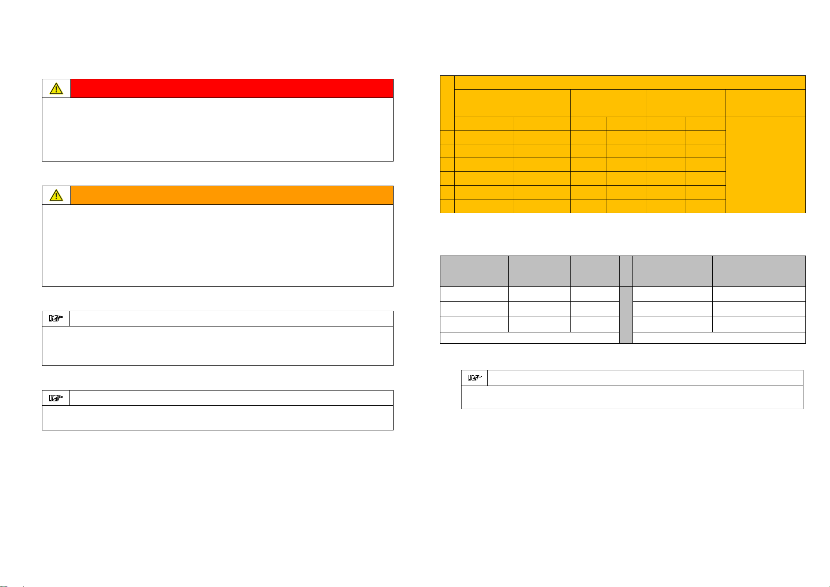
Pressure Ranges
ADJUSTABLE RANGES
MAXIMUM
OPERATING
PROOF
HYSTERESIS
PSI
(bar)
PSI
(bar)
PSI
(bar)
15% OF FULL
SCALE
A
5.8 - 87
(0.4 - 6)
725
(50)
1200
(80)
B
29 - 290
(2.0 - 20)
725
(50)
1200
(80)
C
43 - 650
(3.0 - 45)
725
(50)
1200
(80)
D
43 - 2610
(3.0 - 180)
3600
(250)
8700
(600)
E
430 - 5000
(30 - 350)
6500
(450)
8700
(600)
F
800 - 8700
(55 - 600)
8700
(600)
13050
(900)
Fig. 9: Compact pressure switch PSW8 Series – Pressure Ranges
Electrical Ratings Silver Contacts
SILVER
CONTACTS
INDUCTIVE
LOAD
RESISTIVE
LOAD
GOLD CONTACTS
RESISTIVE LOAD
30 VDC
3.0 A
3.0 A 30 VDC
0.1 A
250 VDC
0.2 A
0.2 A
125 VAC
0.1 A
125 VAC
3.0A
5.0 A
U max = 28 V
I max = 50mA
MINIMAL CAPACITANCE: 160 mA @ 5 VDC
MINIMAL CAPACITANCE: 0.1 mA @ 5 VDC
Fig. 10: Electrical ratings
IMPORTANT
Using a fuse of the maximum current rating from the table above according to the load switched is
recommended.
Operating life time
Normal expected service life (expressed in the number of cycles over the full adjustment range) is
approximately 1 million cycles for the pressure switch. This may be extended to 2.5 million cycles
maximum if only a part of the adjustment range is used (about 20%).
Switch sensor life may also be effected negatively by:
-Media not compatible with the wetted materials.
-Rapid pressure changes in the system,
1. In case of diaphragm switches >30 cycles/minute,
2. In case of piston switches >60 cycles/minute.
-System cycling pressure exceeding the top of the adjustable range.
The proof pressure may not be exceeded; otherwise the switch may be damaged. Careful selection
of the pressure range can have a positive effect on the service life of the switch.
8
3
Page 7
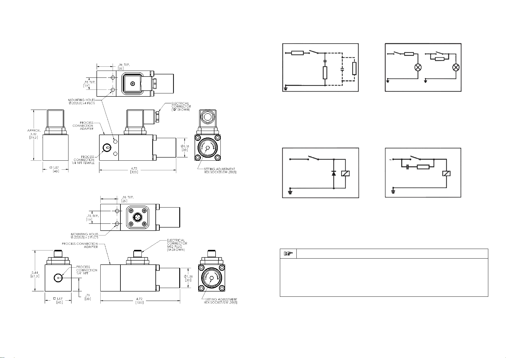
7 Technical Data
See data sheet
Dimensions in inch[mm]
Fig. 7: Compact pressure switch PSW8 Series – D TYPE Electrical Option
Fig. 8: Compact pressure switch PSW8 Series – M TYPE Electrical Option
Fig. 1: Protection in case of
capacitive loads R1:
Protection against starting
current rushes R2,R3:
Protection against high
discharge currents
Fig. 2: Lamp load provided with
resistance in parallel or
series connection to
switch of condensators
Fig. 3: Protection in case of
continuous current and
inductive load by recovery
diode
Fig. 4: Protection in case of
alternating current and
inductive load by RC-link
Set point adjustment
IMPORTANT
Factory-Provided: pressure switch point setting
For pressure switches that have been factory set the setting will be printed on the nameplate
Warranty is not applicable for any changes that may occur due to transportation or installation.
For critical applications we recommend the setting is checked and re-set if necessary after
installation and wiring of the pressure switch.
In pressure switches, a displacement of the pressure sensing element (piston) occurs with a
change in pressure. Following the displacement of the pressure sensing element operates a
microswitch.
Upon delivery of the product, the set points are likely to be found in the middle of the adjustable
range. On request, factory-set points may be set at our factory. In this event, the set point will be
indicated on the nameplate, i = increasing, d = decreasing.
MS R R
MS
MS
U
=
Diode
Load
MS U c
Load
R
7
4
Page 8
The set point is adjusted by turning the captive adjustment screw (see Fig.7 & 8, page 7)
Allow pressure switch to reach the desired switch pressure.
Turn adjustment screw clockwise or counter-clockwise to activate the micro switch
IMPORTANT
Please consult the wiring diagram for the contact status at atmospheric pressure.
Precise adjustment of set point to actuate on increasing pressure
1. Cycle unit 5 times up to max. operating range
2. Lower system pressure to 0 psi.
3. Increase pressure slowly and check if micro switch is actuated at desired switch pressure.
4. If necessary, readjust by turning the adjustment screw
5. Repeat preceding steps (2. to 4.) until microswitch operates at desired switch pressure.
Precise adjustment of set point to actuate on decreasing pressure
6. Increase pressure up to a point clearly above the desired switch pressure (at least, switch
pressure plus max. hysteresis; not above max. operating pressure).
7. Lower pressure slowly and check if micro switch is actuated at desired switch pressure.
8. If necessary, readjust by turning the adjustment screw
Repeat preceding steps (6. to 8.) until microswitch operates at desired switch pressure.
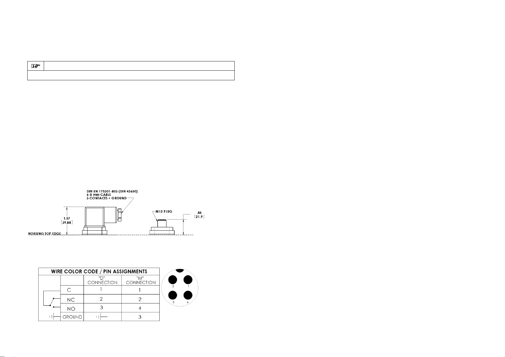
Electrical connections, Dimensions in inch[mm]
"D" Electrical Connector "M" Connector
Fig. 5: Standard Mating Connector
Wiring code (contact status at atmospheric pressure)
Fig. 6: Pin Call-Outs
8 Maintenance/Cleaning
The pressure switch is maintenance free. Checking the set points lies within the discretion of the
user. The usual preventive maintenance work in accordance with the PED guidelines must always
be carried out.
Please note that small set point drifts may occur during the initial use of the switch (run-in period).
Larger or continuing set point drifts during the normal use of the switch may indicate that the
measuring system is not used correctly within the specified limits, exceeding the design criteria or
is worn-out. This might lead to metal fatigue of the measuring system and it therefore should be
replaced before an ultimate rupture of the metal might take place. Please consult OMEGA for
guidelines.
5
6
"M" Connector
 Loading...