

Page 1
P
S
W
2100
INSTRUCTION
SHEET
M-5762/0320
Shop online at omega.com e-mail: [email protected]
For latest product manuals: omegamanual.info
Page 2
Pressure switch is powered by an external power supply. The
!
power supply should be in accordance with relevant standards
stipulated by energy limitation circuit, and special attention should
be given to the high-voltage that may exist in the circuit.
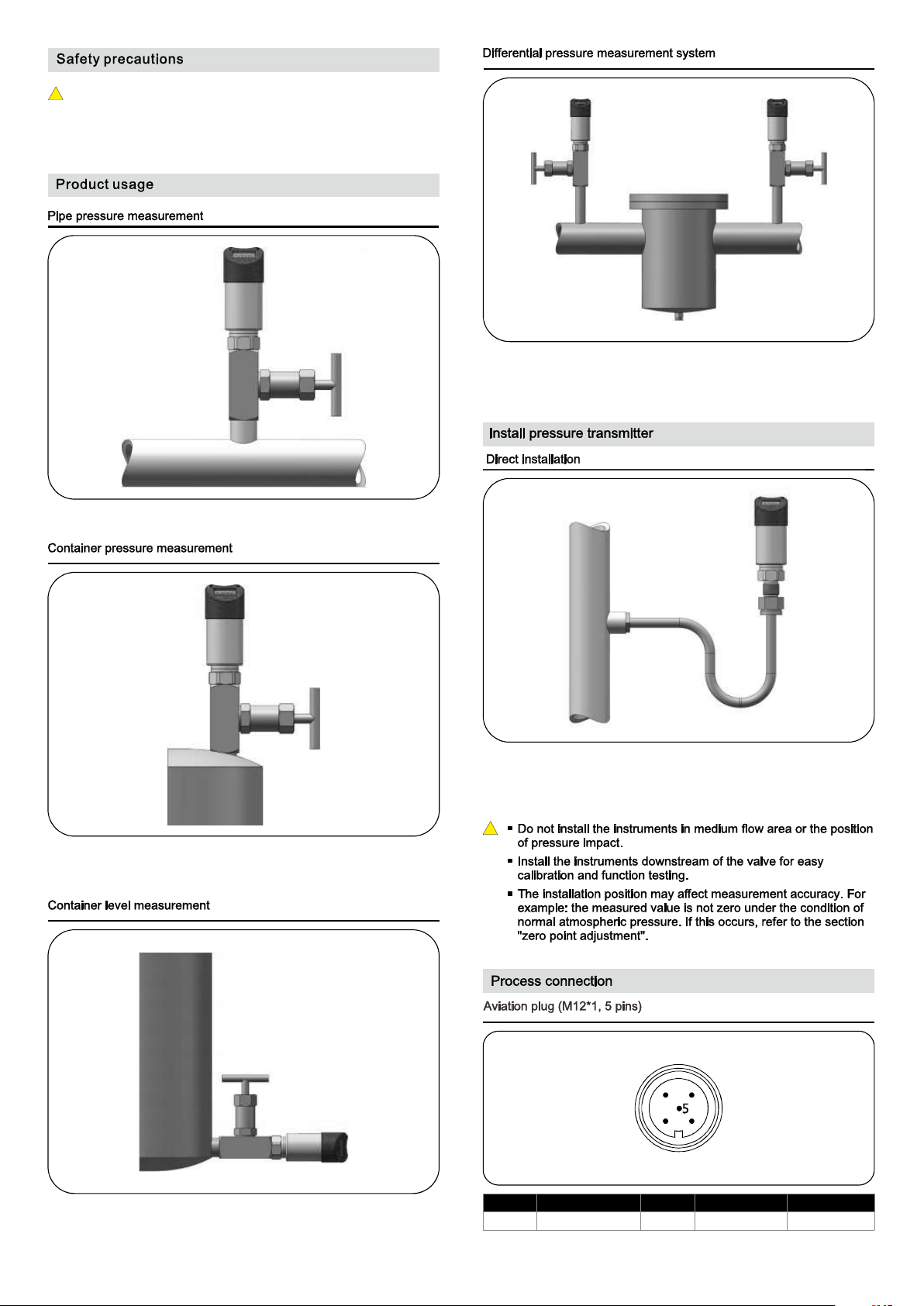
Can be installed with adapters on the pipe directly.
Two pressure switches can be used to create a differential
measurement system, commonly used in the filter control or closed
container level measurement.
After the pressure vessel is stable, slowly open the shut-off valve to
in
start measuring.
Can be used for liquid level measurement in open container. Media
compatibility should be considered.
Light-weight pressure can be mounted directly on the pressure
leading tube. When the maximum torque force can not
switch
installing
exceed 50Nm.
!
4
3
1
2
1 2
Pow er+
Transistor output 2
3
Power-
4 5
Transistor output 1 *Signal+
*Signal: 4~20mA, 1-5VDC
Page 3
Power
Label
1
+
brown/1
white/2
SW1
S+
-
SW2
5
6
R2
blue/3
4
3
black/4
1
2
gray/5
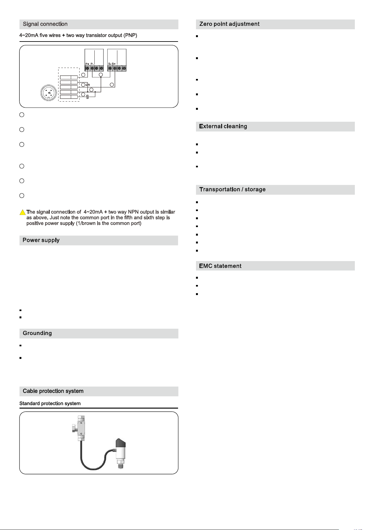
Connect the positive power supply (P+) to the terminal 1/brown
1
Signal
2
R1
3
4
4/black wire is the common port
;
wire of pressure switch;
Connect the negative signal module (S-) to the negative power
2
supply(P-);
Connect the negative signal module (S-) to the negative power
3
supply(P-) and then connect to the terminal 4/black wire of
pressure switch;
Connect the positive signal module (S+) to the terminal 3/blue wire
4
of pressure switch;
Connect the first way transistor to the terminal 2/white wire of
5
pressure switch;
Connect the second way transistor to the terminal 5/gray wire of
6
pressure switch.
!
A zero point adjustment should be made after installation to counter
any effects the mounting position may have on the zero setting.
When performing the adjustment, the vessel should be completely
empty, with no pressure or media on the measuring diaphragm and the
vessel exposed to atmospheric air. With unit powered, short the key-z
wire (blue) to the + power lead. hold for 5 seconds, when removed the
zero point will be adjusted.Set the zero point three weeks after
installation to ensure accuracy, and reset zero point annually.
Standard current signal output+transistor output: 12-30VDC,
Transistor output: 12-30VDC.
A zero point adjustment should be made after installation to
counter any effects the mounting position may have on the zero
setting.
When performing the adjustment, the vessel should be completely
empty, with no pressure or media on the measuring diaphragm and
the vessel exposed to atmospheric air.
With unit powered, short the key-z wire (blue) to the + power lead.
hold for 5 seconds, when removed the zero point will be adjusted.
Set the zero point three weeks after installation to ensure
accuracy, and reset zero point annually.
Set PV=0 each year.
Please observe the following when cleaning:
Use a cleaner that is compatible with pressure switch materials
Clean carefully to ensure that the pressure port isn't damaged (e.g.
with a sharp object)
Do not directly spray electrical connection or gauge vent with water
or cleaner.
Do not store outside.
Keep dry and dust-free.
Do not expose to the corrosive medium.
Avoid solar radiation.
Avoid mechanical shock and vibration.
Storage temperature: -40-185 (-40-85℃).℉
Maximum relative humidity: 95%.
EMC equipment instructions 2014/30/EU.
CE mark suggests the instruments are in line with EU standards
Users need to ensure the whole equipment conform to all the
applicable standards.
A cable with a shielded twisted-pair signal is recommended to
avoid ground loop.
The built-in transient resistance module is only effective if properly
grounded. The metal body and internal grounding terminals should
be directly grounded.
To safeguard against liquid media potentially traveling along the cable
into the terminal box, the cable should be configured in a U-shape as
shown, with the bottom of the “U” lower than the bottom of the pressure
switch.
Page 4
Lab le Ite m Settin g ran ge Des cri pti on
SPx ( Note1) OU T upper lim it - ~99 999 99 999 Upp er li mit v alu e of tr ans ist or ou tpu t
Rpx OU T lowe r lim it - ~99 999 99 999
SPD Tx OU T outp ut de lay
RPD Tx OU T rese t del ay 0 0 60 0(S. ~ . ) Del ay time be for e tra nsi sto r out put r ese t
Mod ex
OU T
wor king mo de
0 0 60. 0(S). ~
Mod ex=0 No ou tput. O UTx k eeps r ese t stat e
Mod ex=1
Mod ex=2
Mod ex=3
Mod ex=4
Low er limi t valu e of tran sis tor ou tpu t
Del ay time be for e tra nsi sto r out put a cti ve
Mea sured v alu e > SPx, d elay S PDTx, O UTx act ive (N ote2)
Mea sured v alu e < RPx, d elay R PDTx, O UTx res et (0V , the s ame be low)
Mea sured v alu e > SPx, d elay S PDTx, O UTx res et
Mea sured v alu e < RPx, d elay R PDTx, O UTx act ive
RPx < m easur ed val ue < SPx, d elay S PDTx, O UTx a ctiv e
Mea sured v alu e > SPx or m eas ured v alue < R Px, d elay R PDT x, OUT x res et
Mea sured v alu e > SPx or m eas ured v alue < R Px, d elay S PDTx, O UTx ac tive
RPx < m easur ed val ue < SPx, d elay R PDTx, O UTx res et
Notes: 1. x =1 or 2, SPx ≥ RPx
2. Active electrical level is 2V lower than power supply level. Eg, power supply level is 24V, then active electrical level is 22V.
P
SPx
RPx
OUT
Active
Reset
OUT
Active
Reset
OUT
Active
Reset
OUT
Active
Reset
OUT
Active
Reset
P: pressure
T: time
x=1 or 2
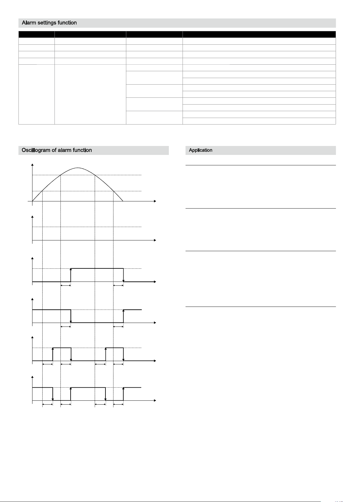
Modex 0 No output= ,
Modex 1 HNO Upper limit alarm/ hysteresis function= , ( )
SPDTx RPDTx
Modex 2 HNC Lower limit alarm/ hysteresis function= , ( )
RPDTx SPDTx
Modex 3 FNO Window mode/ delayed alarm in window= , ( )
RPDTx RPDTxSPDTx SPDTx
Modex 4 FNC Window mode/ delayed alarm out window= , ( )
SPDTx SPDTxRPDTx RPDTx
High level alarm
Output alarm signal when pressure is higher than 145Psi.
Normal setting: SP1=145Psi, RP1=137.78Psi, Mode1=1, SPDT1=1,
RPDT1=1. Pressure rises to 145Psi, delay 1s, OUT1 active (on);
pressure drops to 137.78Psi, delay 1s, OUT1 reset (off)
T
Low level alarm
Output alarm signal when pressure is lower than 145Psi.
Normal setting: RP1=145Psi, SP1=152.28Psi, Mode1=2, SPDT1=1,
RPDT1=1. Pressure drops to 145Pssi, delay 1s, OUT1 active (on);
pressure rises to 152.28Psi, delay 1s, OUT1 reset (off)
T
Window function
Starting devices normally requires pressure is within the range
72.51~145Psi. Normal setting: SP1=145Psi, RP1=72.51Psi, Mode1=3,
SPDT1=1, RPDT1=1. Pressure rises to 145Psi, delay 1s, OUT1 active
T
(on); pressure rises to 145Psi, delay 1s, OUT1 reset (off); Pressure
drops to 145Psi, delay 1s, OUT1 active (on); pressure drops to
72.51Psi, delay 1s, OUT1 reset (off)
Automatically keep pressure function
Applying pressure on a device by a compressor and keeping the
T
pressure within the range 72.51~145Psi need two ways output. The
first way output controls the compressor and the second way output
controls the device. The first way output setting: SP1=130.53Psi,
RP=87.02Psi, Model=2, SPDT1=1, RPDT1=1. The first way contact
controls the power supply of compressor through intermediate relay
to disconnect once the pressure is higher than 130.53Psi and connect
T
once the pressure is lower than 87.02Psi. The pressure value needs to
be controlled within 87.02~130.53MPa. The second way output setting:
SP2=145Psi, RP2=72.51Psi, Mode2=3, SPDT2=1, RPDT2=1. Once
the working pressure of device is not within the range
72.51Psi~145Psi, after 1s, the second way contact controls the alarm
output of the device through intermediate relay to ensure the abnormal
T
working pressure of the device can be discovered and handled in time.
Page 5
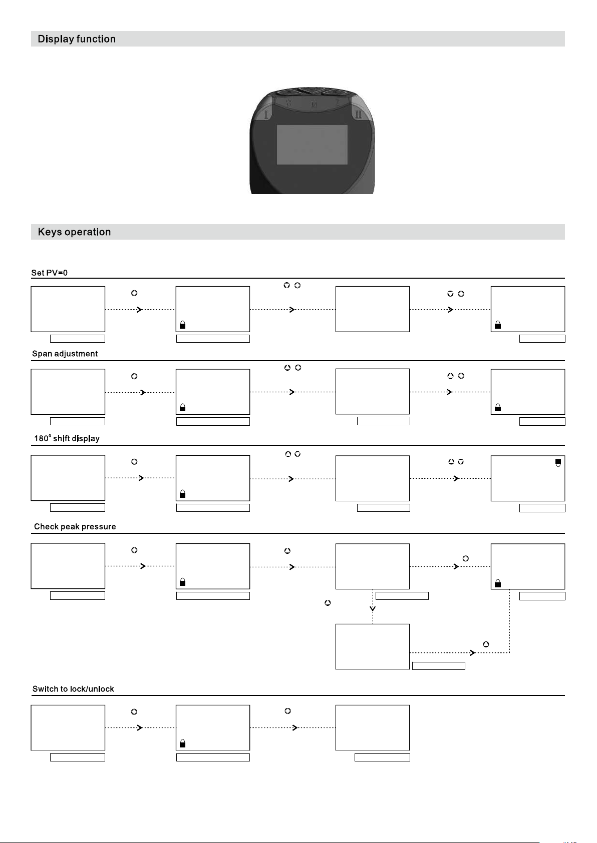
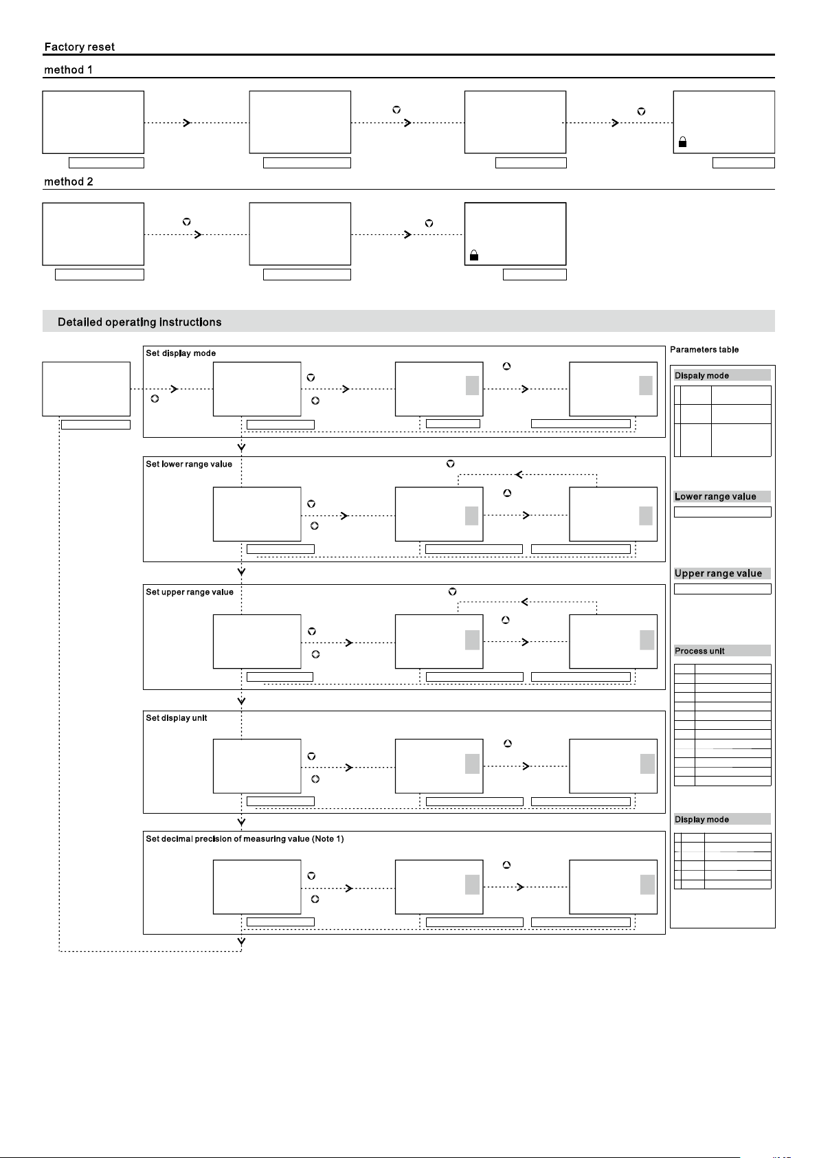
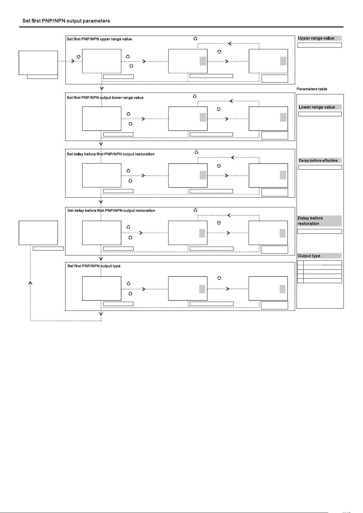
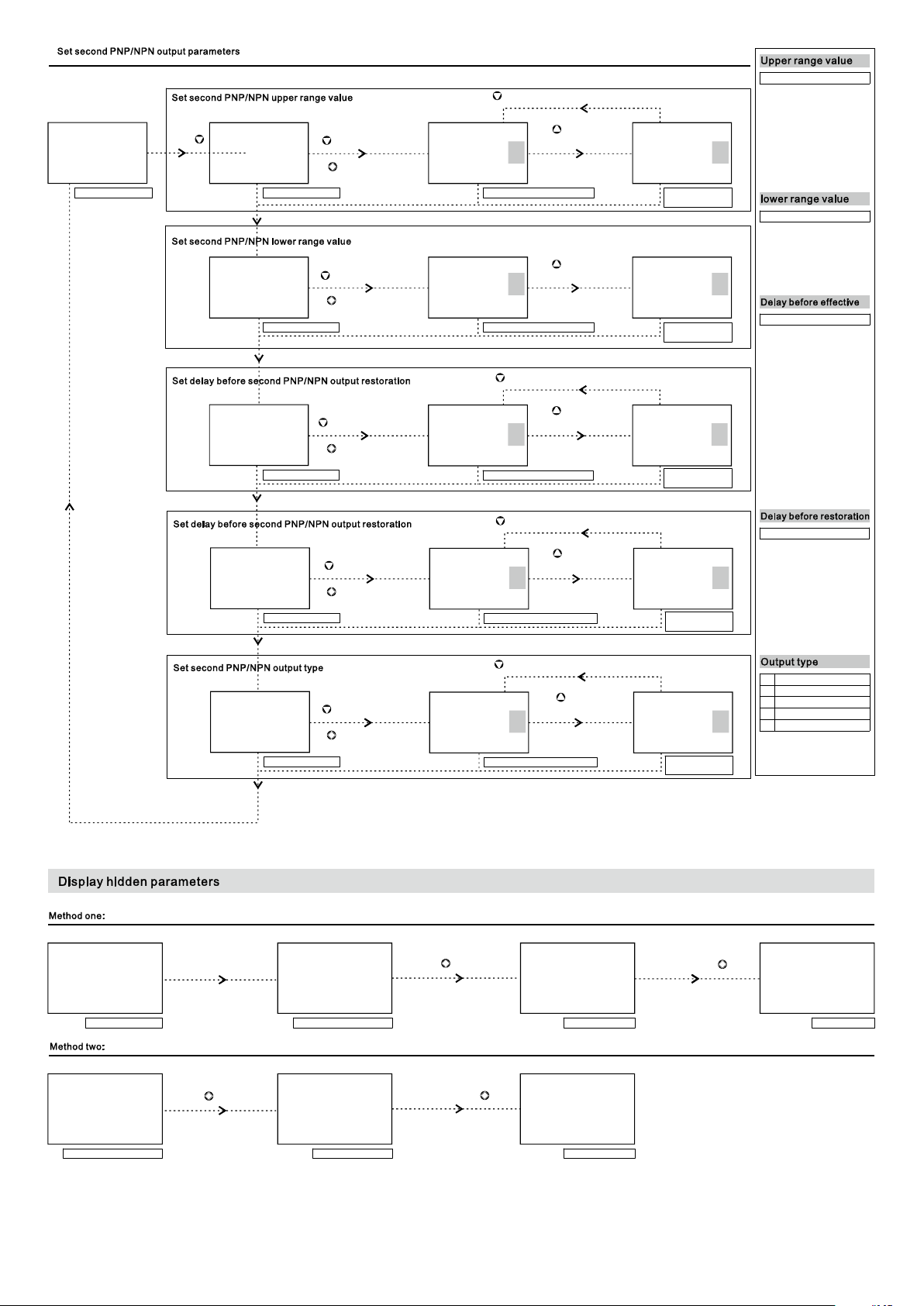
Displ ay module i s used fo r field a djust ment to complete all the pa ramet ers setti ng and si te conf igura tion before measuring .
For example, factory se tting p arame ters: pre ssure r ange -10-100Ps i, disp lay uni t Psi, op er ate in the atmos phere .
Z
M
+
3 secon ds
0.000
PVC1r S ucces s!
M
Release at the
Z
+
same ti me
0.010
Psi
Mea surin g inte rfac e
M
Press at least 3
secon ds
Press at the
same ti me at least
0.010
Psi
Mea surin g inter face wi th lock
0.000
Psi
Fin ished i nter face
100.10
Psi
Mea surin g inte rfac e
0.010
Psi
Mea surin g inte rfac e
0.010
Psi
Mea surin g inte rfac e
M
Press at least 3
secon ds
M
Press at least 3
secon ds
M
Press at least 3
secon ds
100.10
Psi
Mea surin g inter face wi th lock
0.010
Psi
Mea surin g inter face wi th lock
0.010
Psi
Mea surin g inter face wi th lock
M
S
Press at the
+
same ti me at least
3 secon ds
Z
S
Press at the
+
same ti me at least
3 secon ds
S
Press at least 3
secon ds
Press at least 3
secon ds
100.00
URV Cal S ucces s!
Suc cessf ul int erfa ce
0.010
Rotating Success!
Suc cessf ul int erfa ce
Max Pressure:
100.00
M key for exit!
S
Data cleared!
0.010
Will be exit!
Release at the
Release at the
Suc cessf ul int erfa ce
Suc cessf ul int erfa ce
M
S
+
same ti me
ZS
+
same ti me
Press
Release
100.00
Psi
Fin ished i nter face
Psi
010.0
Fin ished i nter face
M
0.010
Psi
Fin ished i nter face
S
0.010
Psi
Mea surin g inte rfac e
M
Press at least 3
secon ds
0.010
Psi
Mea surin g inter face wi th lock
M
Press at least 3
secon ds
0.010
Psi
Mea surin g inter face
Page 6
Z
0.010
Power off
Press , powe r on
Data restor e OK
!Please free the key
Release
Psi
Mea surin g inte rfac e Fin ished i nter face
Int erface befo re powe r on S ucce ssfu l inter face
Z
0.010
Psi
Press , powe r on
Z
Data restor e OK
Release
!Please free the key
Z
0.010
Psi
Int erface befo re powe r on Fin ished i nter face
Pre ssu re Unit & Pr essure Uni t &
0.010
Ps i
Mea surin g inter face
M
confi rm
and enter
next me nu
Ran 9999 9 99999:- ~
Ran 9999 9 99999:- ~ Ran 9999 9 99999:- ~
kPa kPa Mpa
Int erface befo re powe r on
DisMod
Cur rent par amete rs
- .10 00
LRV
Cur rent par amete rs
100.00
URV
cur rent par amete rs
Unit
Cur rent par amete rs
Z
ent er settings
0
M
confirm and
enter n ext menu
Z
ent er settings
M
confirm and
enter n ext menu
Z
ent er settings
M
confirm and
enter n ext menu
Z
ent er settings
1
M
confirm and
enter n ext menu
DisMod
Set p aram eter s
Z
con firm an d enter next menu
Ran 99999 99 999:- ~
- .10 00
Dis play se lect ed para meter s
Z
con firm an d enter next menu
100.00
Dis play se lect ed para meter s
Dis play se lect ed para meter s
S
mod ify
param eters
0
Dis play mo difie d param eters
S
mod ify
param eters
LRV
Dis play mo difie d param eters
S
mod ify
param eters
URV
Dis play mo difie d param eters
S
mod ify
param eters
1 2
Unit Unit
Dis play mo difie d param eters
SPn P & RP n&
Ran 99999 99 999:- ~
-10 01.
Ran 9999 9 99999:- ~
100.01
DisMod
LRV
URV
2
0
Pressure &
Unit
1
XXX% &
P & Unit
2
Spn & P
& RPn
0
1
2
3
4
5
6
7
8
9
10
11
12
Two ro ws disp lay: PV
& Unit
Three rows dis play:
percent age; pv & unit
Three rows dis play:
SP1&RP1 al ternate
display, SP 2&RP2
alternat e display
-99999~ 99999
-99999~ 99999
-
kPa
M a
P
Pa
bar
mBar
si
P
mH2O
mmH2O
cmH2O
mmHg
Torr
Atm
XXX XX
1
DotPo s
Cur rent par amete rs
Z
enter setting s
M
confirm and
enter n ext menu
S
xx xxx XXX X.X
modify
param eters
1 2
DotPo s
Dis play se lect ed para meter s
Dis play mo difie d param eters
DotPo s
Auto
0
xxxxx
1
xxxx.x
2
xxx.xx
3
xx.xxx
4
x.xxxx
5
Optimal dis play mode
Integer, n o decimal
One decimal
Two decimal
Three decim al
Four decima l
Page 7
0.010
kP a
Mea surin g inter face
Press
Ran 9999 9 99999:- ~ Ran 9999 9 99999:- ~
S
90.00 90.00
Cur rent par amete rs
Ran 9999 9 99999:- ~
80.00
Cur rent par amete rs
Z
enter se ttings
M
confirm and
SP1
enter n ext menu
Z
enter setting s
M
confirm and
RP1
enter n ext menu
Ran 9999 9 99999:- ~
Z
confirm and ent er next menu
S
modify
param eters
SP1
Dis play se lect ed para meter s
Z
confirm and ent er next menu
S
modify
80.00
Dis play se lect ed para meter s
confirm and ent er next menu
param eters
RP1
Z
Ran 9999 9 99999:- ~
90.01
Dis play mo difie d
par amete rs
Ran 9999 9 99999:- ~
80.01
Dis play mo difie d
par amete rs
-99999~ 99999
SP1
-99999~ 99999
RP1
0.010
kP a
Mea surin g inter face
Ran 0 00 6 0 0 S: . ~ .
Ran 0 00 6 0 0 S: . ~ .
No Ou t
Z
enter setting s
0 0.
RPDT1
Cur rent par amete rs
enter n ext menu
Z
enter setting s
0 0.
SPDT1
Cur rent par amete rs
enter n ext menu
Z
enter setting s
0
Mo de1
Cur rent par amete rs
enter n ext menu
M
confirm and
M
confirm and
M
confirm and
Ran 0 00 6 0 0 S: . ~ .
Dis play se lect ed para meter s
Ran 0 00 60 0S: . ~ .
No Ou t
Mo de1 Mo de1
S
modify
Ran 0 00 6 0 0 S: . ~ .
param eters
0.0
RPDT1
Z
confirm and ent er next menu
S
modify
param eters
Ran 0 00 6 0 0 S: . ~ .
0 0.
SPDT1
Dis play se lect ed para meter s
S
modify
param eters
Hysteresi s P S Pn, >
0 1
Dis play se lect ed para meter s
0.1
RPDT1
Dis play mo difie d
par amete rs
0 1.
SPDT1
Dis play mo difie d
par amete rs
Dis play mo difie d
par amete rs
0
No Out
1
Hysteres is P S Pn, >
2
Hysteres is P R Pn, <
3
Window RPn P SPn, < <
4
Window P RPn P S Pn, < , <
0.0-60.0 S
0.0-60.0 S
Page 8
Z
confirm and ent er next menu
-99999~ 99999
0.010
kP a
Mea surin g inter face
Press
Ran 9999 9 99999:- ~ Ran 999 99 99 999:- ~
Z
50.00 50.00 50.01
Cur rent par amete rs
Ran 99 999 99 999:- ~
30.00
Cur rent par amete rs
Ran 0 0 0 6 0 0S: . ~ .
0 0.
SPDT2
Cur rent par amete rs
Ran 0 0 0 6 0 0S: . ~ .
0 0.
RPDT2
Cur rent par amete rs
Z
enter setting s
M
confirm and
SP2
enter n ext menu
Z
enter se ttings
M
confirm and
RP 2 RP2 RP2
enter n ext menu
Z
enter se ttings
M
confirm and
Ran 99 999 99 999:- ~
Ran 0 0 0 6 0 0S: . ~ .
enter n ext menu
Z
enter setting s
M
confirm and
Ran 0 0 0 6 0 0S: . ~ .
enter n ext menu
SP2 SP2
Dis play se lect ed para meter s
30.00
Dis play se lect ed para meter s
Z
confirm and ent er next menu
0.0
SPDT2
Dis play mo difie d param eters
Z
confirm and ent er next menu
0.0
RPDT2
Dis play mo difie d param eters
S
modify
param eters
S
modify
param eters
S
modify
param eters
S
modify
param eters
Ran 99 999 99 999:- ~
Dis play mo difie d
par amete rs
Ran 99 999 99 999:- ~
30.01
Dis play mo difie d
par amete rs
Ran 0 0 0 6 0 0S: . ~ .
Dis play mo difie d
par amete rs
Ran 0 0 0 6 0 0S: . ~ .
Dis play mo difie d
par amete rs
-99999~ 99999
0 0 60 0S. - .
0.1
SPDT2
0 0 60 0S. - .
0.1
RPDT2
Z
confirm and ent er next menu
No O ut No O ut
Mode2
Cur rent par amete rs
Power off
Z
enter setting s
0
M
confirm and
enter n ext menu
Press , power on
0
Mode2 Mode2
Dis play mo difie d param eters
M
0.010 0.010
S
modify
param eters
It will display all
parameters! Please free
the key!
Hysteresi s P S Pn, >
Dis play mo difie d
par amete rs
Release
2
0
No Out
1
Hysteres is P S Pn, >
2
Hysteres is P R Pn, <
3
Window RPn P SPn, < <
4
Window P RPn P S Pn, < , <
M
Psi
Cur rent par amete rs
Press , power on
Int erface befo re powe r on
M
It will displ ay all
parameters! Please free
the key!
Release
M
Fin ished i nter face
0.010
Fin ished i nterf ace
Psi
Int erface befo re powe r on Su ccessf ul inte rface
Fin ished i nter face
Psi
Page 9
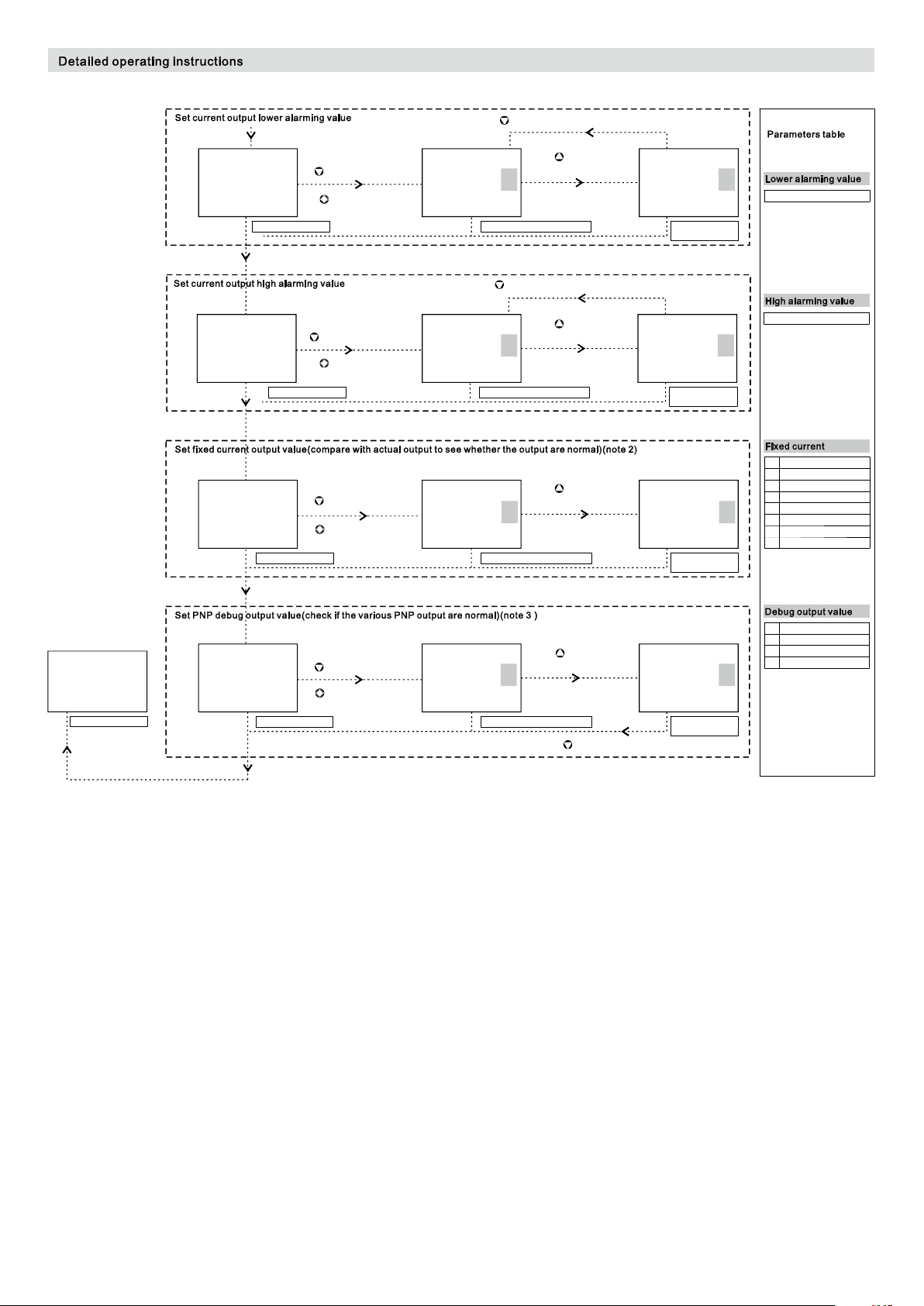
After above operation , press M g et into DisMod -L RV-Unit para meters setting ,and pr ess M aga in get in to hidden parameters se tting
Z
confirm and ent er next menu
Ran 3. 500 ~3. 800: Ran 3. 500 ~3. 800:
3.700
mA A OL C
Cur rent par amete rs
Ran 20 .80 0~2 4.0 00:
23.000 23.000 23.001
mA A OH C
Cur rent par amete rs
Mea surin g Outpu t
Fi x COut
Cur rent par amete rs D ispl ay sel ecte d para meters
Z
enter setting s
M
confirm and
enter n ext menu
Z
enter setting s
M
confirm and
enter n ext menu
Z
enter setting s
0 0 1
M
confirm and
enter n ext menu
3.700
mA A OL C
Dis play se lect ed para meter s
Z
confirm and ent er next menu
Ran 20 .80 0~2 4.0 00: Ran 20 .80 0~2 4.0 00:
mA A OH C
Dis play se lect ed para meter s
Mea surin g Outpu t
Fi x COut
S
modify
param eters
S
modify
param eters
S
modify
param eters
Ran 3. 500 ~3. 800:
3.701
mA A OL C
Dis play mo difie d
par amete rs
mA A OH C
Dis play mo difie d
par amete rs
Out put 3.800mA
Fi x COut
Dis play mo difie d
par amete rs
0
Measuri ng Output
1
Output 3.80 0mA
2
Output 4.00 0mA
3
Output 8.00 0mA
4
Output 12.0 00mA
5
Output 16.0 00mA
6
Output 20.0 00mA
7
Output 20.8 00mA
3.500-3. 800mA
20.800-2 4.000mA
0
Both Off!
1
Fist On!
2
3
Second On!
Both On!
0.010
kPa
Mea surin g inter face
Both off
Z
enter setting s
0
M
Fi xTOut
Cur rent par amete rs Dis play se lect ed para meter s
confirm and
enter n ext menu
Fi x TOut
param eters
0
S
modify
Z
confirm the out put
1
FixTOut
Dis play mo difie d
par amete rs
Note 1: By default, the system shows optimal precision according to measuring range. Eg: While the measuring range of product is 0-10kPa,
measuring value shows 0.000-10.000; while the measuring range of product is 0-100kPa, the measuring value shows 0.00-100.00. If DotPos
parameters value and measuring range do not match, the system will automatically ignore and then process by default.
Eg: While the measuring range of product is 0-10kPa, if operator makes DotPos=5, the system will regard it as ineffectiveness and the measuring
value will still shows 0.000-10.000 by default; while the measuring range of product is 0-100kPa, if operator makes DotPos=4 or 5, the system will
regard it as ineffectiveness and the measuring value will still shows 0.00-100.00 by default.
Note 2:Use FixCOut parameters to control fixed current ,to confirm whether current output is ok. Changing fixed current value by press S and confirm
by Z.
Note 3:Use FixTOut parameters to control 2 way PNP by mannual operation, to confirm whether PNP output is ok. Changing fixed current value by
press S and confirm by Z.
Page 10
8
 Loading...