

Page 1
User’s Guide
Shop online at
omega.com
e-mail: [email protected]
For latest product manuals:
omegamanual.info
DUAL SEAL
CERTIFIED
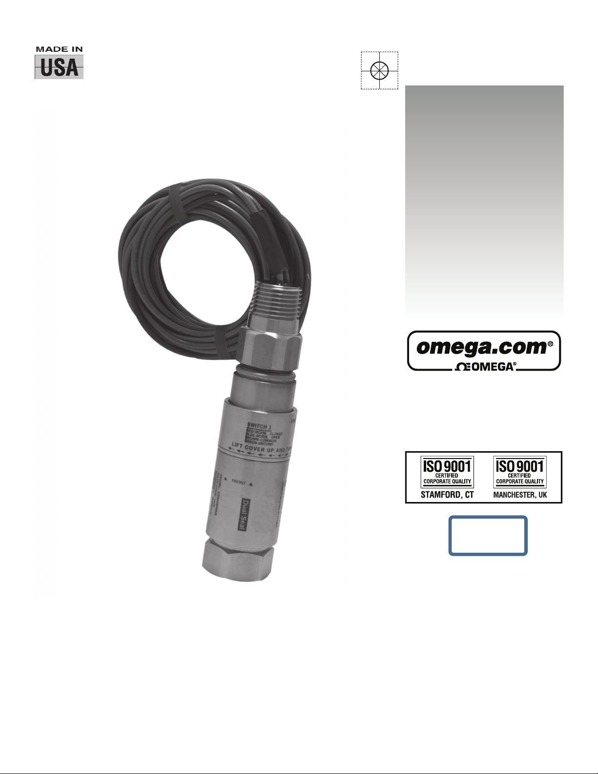
PSW12 SERIES
Pressure Switches
Page 2

omega.com [email protected]
Servicing North
America:
U.S.A.:
Omega Engineering, Inc., One Omega Drive, P.O. Box 4047
Stamford, CT 06907-0047 USA
Toll-Free: 1-800-826-6342 (USA & Canada only)
Customer Service: 1-800-622-2378 (USA & Canada only)
Engineering Service: 1-800-872-9436 (USA & Canada only)
Tel: (203) 359-1660 Fax: (203) 359-7700
e-mail: [email protected]
For Other Locations Visit
omega.com/worldwide
The
information
contained in this
document
is believed to be correct, but OMEGA accepts no
liability
for any errors it contains, and
reserves
the right to alter
specifications without notice.
WARNING: These products are not designed for use in, and should not be used for, human
applications.
Page 3
PSW12 Series
Explosion-Proof Pressure Switch
Part Numbers: PSW12T- AS to HS
PSW12T- AD to HD
PSW12V- AS to HS
PSW12V- AD to HD
Please read all instructional literature carefully and thoroughly before starting.
GENERAL
MISUSE OF THIS PRODUCT MAY CAUSE EXPLOSION AND PERSONAL INJURY.
THESE INSTRUCTIONS MUST BE THOROUGHLY READ AND UNDERSTOOD
BEFORE UNIT IS INSTALLED.
THIS EQUIPMENT IS SUITABLE FOR USE IN CLASS I, DIVISIONS 1 & 2, GROUPS
A, B, C AND D; CLASS II, DIVISIONS 1 & 2, GROUPS E, F AND G; CLASS III; OR
NON-HAZARDOUS LOCATIONS ONLY. -50 °C (-58 °F) ≤ Tamb. ≤ 80 °C (176
°F), ENCLOSURE TYPE 4X.
Class I, Division 1 and 2, Groups A, B, C & D
Class II, Division 1 and 2, Groups E, F & G
Class III
Class I, Zone 1, Group IIC
Enclosure Type 4X
Pressure: UL 508 & 1203; CSA C22.2 No. 14, 25 & 30 File # E106732
Dual Seal certified to ISA 12.27.01 (meets CEC secondary seal
requirements)
PRIOR TO INSTALLATION, CHECK THE WETTED PARTS MATERIAL FOR
COMPATIBILITY TO THE PROCESS MEDIA.
THE DUAL SEAL DEVICE METHOD OF PRIMARY SEAL FAILURE ANNUNCIATION IS
VISABLE LEAKAGE FROM THE ENCLOSURE. DEPENDING UPON MEDIA SENSED,
ADDITIONAL METHODS OF LEAK DETECTION MAY BE REQUIRED.
The PSW-12 Series switch utilizes a diaphragm sensor to detect a pressure change.
The response, at a predetermined set point, actuates a SPDT or DPDT snap-acting
switch, converting a pressure signal into an electrical signal. Control set point may
be varied by turning the internal slotted adjustment screw according to procedures
outlined in Part II-Adjustments.
Date code format on enclosure is “YYWW” for year and week.
Part I - Installation
Tools Needed
1-1/6" Open end wrench
MOUNTING
ALWAYS LOCATE UNITS WHERE SHOCK, VIBRATION AND AMBIENT TEMPERATURE
FLUCTUATIONS ARE MINIMAL. DO NOT MOUNT IN AMBIENT TEMPERATURE AREAS
EXCEEDING 176°F.
IF SEVERE PRESSURE SURGES ARE EXPECTED, CONSIDER THE USE OF A
PRESSURE SNUBBER.
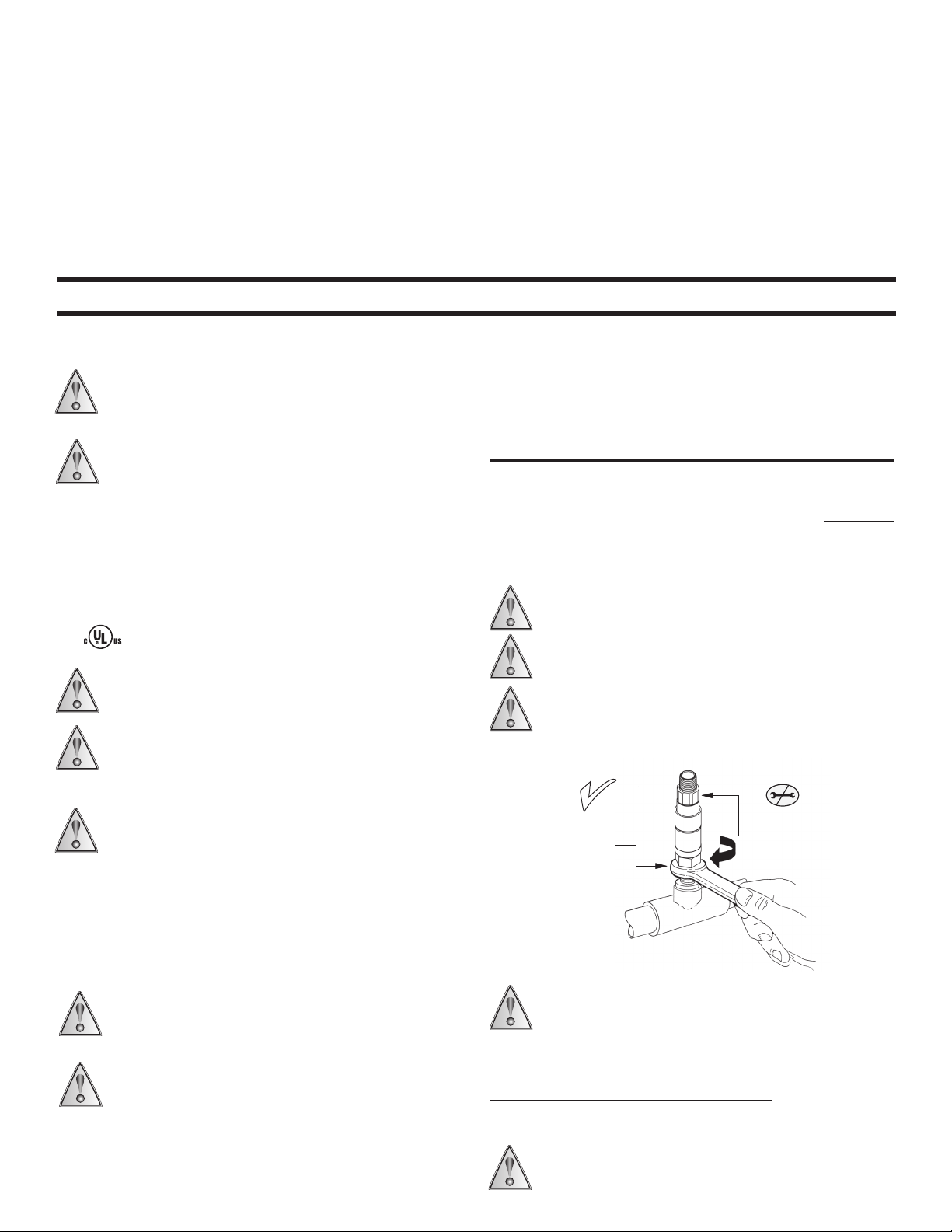
FOR PRESSURE MODELS, MOUNT USING PRESSURE CONNECTION: ALWAYS USE A
WRENCH ON PRESSURE CONNECTION WRENCH FLAT. (SEE FIGURE 1)
PROOF PRESSURE* LIMITS STATED WITHIN THE LITERATURE AND PRINTED
ONTO THE PRODUCT HOUSING MUST NEVER BE EXCEEDED, EVEN BY
SURGES IN THE SYSTEM. OCCASIONAL OPERATION OF THE PRODUCT UP TO
PROOF PRESSURE IS ACCEPTABLE (E.G., START-UP, TESTING). CONTINUOUS
OPERATION SHOULD NOT EXCEED THE DESIGNATED OVER RANGE PRESSURE**
*Proof Pressure - the maximum pressure to which a pressure sensor may be occasionally
subjected, which causes no permanent damage (e.g., start-up testing). (May require
set-point adjustment).
**Over Range Pressure - the maximum pressure to which a pressure sensor may be
continuously subjected without causing damage maintaining set point repeatability.
THE EPOXY RESIN SHALL NOT BE SUBJECTED TO A TEMPERATURE GREATER
THAN 125°C.
THIS PRODUCT DOES NOT HAVE ANY FIELD REPLACEABLE PARTS. ANY
SUBSTITUTION OF COMPONENTS WILL INVALIDATE THIRD-PARTY ISSUED
APPROVALS AND CERTIFICATIONS, AND MAY IMPAIR SUITABILITY FOR CLASS
I, DIVISION 1 LOCATION.
www.omega.com
MOUNT VIA
pressure
connection
Figure 1
THE PRODUCT MAY BE MOUNTED IN ANY POSITION. HOWEVER, IF INSTALLATION
LOCATION RESULTS IN FREQUENT EXPOSURE TO LIQUID IT IS RECOMMENDED
THAT THE PRODUCT BE MOUNTED VERTICALLY WITH THE PRESSURE
CONNECTION DOWN. IF PRODUCT IS TO BE SET AFTER MOUNTING, VERIFY THAT
ADJUSTMENT OPENING IS ACCESSIBLE, “FRONT” MARKING ON NAMEPLATE MUST FACE THE
OPERATOR.
Panel Mounting via 1/2” NPTM Electrical Connection
When panel mounting, mount through 7/8” clearance hole in panel. Use 1/2” conduit nut to
secure in place. Always support the product by holding a wrench on the hex.
TO ATTACH CONDUIT CONNECTION, HOLD ELECTRICAL CONNECTION STEADY WITH
WRENCH ON HEX, THEN THREAD ON CONDUIT.
DO NOT TURN
switch housing
Page 4
WIRING
DISCONNECT ALL SUPPLY CIRCUITS BEFORE WIRING THE PRODUCT. WIRE IN
ACCORDANCE WITH LOCAL AND NATIONAL ELECTRICAL CODES. THE WIRES
SHOULD BE PROTECTED AGAINST MECHANICAL DAMAGE BY USE OF A
CONDUIT OR OTHER SUITABLE MEANS.
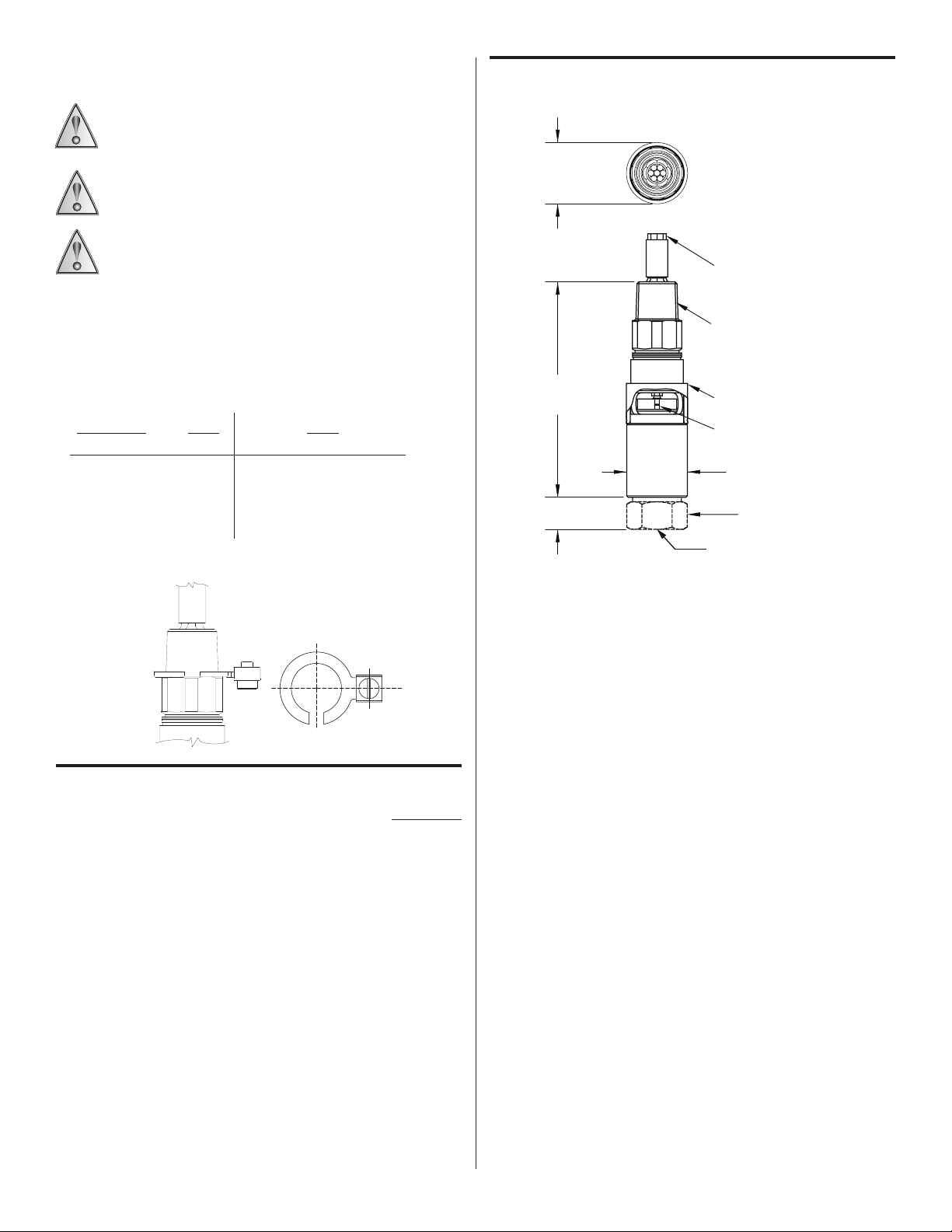
EXTERNAL GROUNDING SCREW (ADD -GND TO OMEGA PART NUMBER) IS
REQUIRED FOR NON-METALLIC CONDUIT SYSTEMS. (SEE FIGURE 2)
ELECTRICAL RATINGS STATED IN THE LITERATURE AND PRINTED ONTO THE
PRODUCT HOUSING MUST NOT BE EXCEEDED. OVERLOAD ON A SWITCH CAN
CAUSE FAILURE ON THE FIRST CYCLE.
Dimensions
1 1/4 [31.7mm]
DIA.
FACTORY SEALED
LEADWIRES 72" LG.
1/2" NPT (male) conduit connection is provided on top of the product with 72” long,
18 AWG leadwires. The product is available with SPDT or DPDT operation. External
grounding screw and clamp is provided with option GND (see figure 2).
Factory sealed leadwires are color coded:
TERMINALS SPDT DPDT
Circuit 1 Circuit 2
Common Brown Brown Yellow
Normally Closed Red Red Black
Normally Open Blue Blue Violet
Ground Green Green
Option GND (External Grounding Screw)
Figure 2
Figure 3
4.4
[111.1 mm]
0.6
[15.2 mm]
E/C: ST/ST
1/2 NPT
ADJUSTMENT
ACCESS COVER
SLOTTED ADJUSTMENT SCREW,
(TURN SLOT CLOCKWISE TO INCREASE SET POINT)
1-1/4 [31.7mm]
DIA.
1-1/16 [27.0 mm]
P/C: 316 ST/ST
1/4 NPT
Part II - Adjustments
Tools Needed
Flathead screwdriver with 3/16” or 1/4” wide blade
1. Connect control to pressure source.
2. With power disconnected, slide cover toward electrical terminations while twisting
it to overcome friction.
3. Connect power to terminals or leads.
4. Insert screwdriver into adjustment slot and turn clockwise to increase
setting or counterclock-wise to decrease setting. (See Figure 3)
For setting on RISE, apply desired pressure and turn adjustment clockwise until switch
actuates (circuit across N.O. and COM terminals closes).
For setting on FALL, apply pressure equal to normal system operating pressure.
Reduce source pressure to setpoint value. Turn adjustment counter clockwise until
switch actuates (circuit across N.C. and COM terminals closes).
www.omega.com
Page 5

WARRANTY/DISCLAIMER
OMEGA ENGINEERING, INC. warrants this unit to be free of defects in materials and
period of 37
months
grace period to the normal three (3) year
This
ensures that OMEGA’s customers receive
If the unit
Department
Upon
malfunctions,
will issue an
examination
charge. OMEGA’s WARRANTY does not apply to defects
including
improper
but not
repair, or
from date of purchase. OMEGA’s WARRANTY adds an
product warranty
maximum
coverage on each
it must be returned to the factory for
Authorized
Return (AR) number
immediately
to cover
evaluation.
upon phone or
handling
product.
OMEGA’s Customer
by OMEGA, if the unit is found to be defective, it will be repaired or replaced at
resulting
limitedtomishandling, improper interfacing, operation
unauthorized modification.
This WARRANTY is VOID if the unit shows evidence
from any action of the
outside of design
having been tampered with or shows evidence of having been damaged as a result of excessive
or current, heat,
conditions
limited
OMEGA
to contact points, fuses, and
is pleased to
OMEGA neither
any
damages
by
OMEGA, either
company
REPRESENTATIONS
TITLE, AND ALL
AND FITNESS FOR A
LIABILITY:
OMEGA with respect to this
indemnification, strict liability
component
consequential, incidental
CONDITIONS:
Component”
applications
activity, medical
as set forth in our basic WARRANTY/DISCLAIMER language, and,
OMEGA and hold OMEGA harmless from any
Product(s) in such a
Direct all
moistureorvibration; improper specification; misapplication;
outside of OMEGA’s control.
Components
in which wear is not
misuse or other
warranted,
triacs.
offer suggestions
assumes
responsibility
that result from the use of its
will be as
verbal or
specified
written. OMEGA warrants
and free of
OF ANY KIND
IMPLIED WARRANTIES INCLUDING
PARTICULAR
The
remedies
of
purchaser
order,
or
upon
which liability
or special
Equipment
under 10
sold by OMEGA is not intended to be used, nor shall it be used: (1) as a
CFR
21 (NRC), used in or with any nuclear
WHATSOEVER, EXPRESSED
PURPOSE ARE HEREBY
otherwise,
is based. In no event shall
damages.
on the use of its various
for any
omissions
or errors nor assumes
productsinaccordance with information
only that the parts
defects. OMEGA MAKES
ANY
WARRANTY
NO OTHER
OR
IMPLIED,
DISCLAIMED. LIMITATION OF
set
forth
whether
herein are
based on
shall
not
exclusive,
and the
contract, warranty,
exceed
the purchase
OMEGA
installation
or activity; or (2) in
or used on humans. Should any Product(s) be used in or with any nuclear
application,
used on humans, or misused in any way, OMEGA assumes no
additionally,
liability
or damage
whatsoever
arising out of the use of
manner.
warranty
RETURN
and repair
requests/inquiries
REQUESTS/INQUIRIES
to the OMEGA Customer Service
BEFORE RETURNING ANY PRODUCT(S) TO OMEGA, PURCHASER MUST OBTAIN AN AUTHORIZED
RETURN (AR) NUMBER FROM OMEGA’S CUSTOMER
PROCESSING
package and on any
The purchaser is
breakage in
FOR
WARRANTY
following information
DELAYS). The assigned AR number should then be marked on the outside of the
correspondence.
responsible
for
shipping
charges, freight, insurance and proper packaging to
transit.
RETURNS, please have
available
BEFORE
the
contacting
OMEGA:
1. Purchase Order number under which the
product
was PURCHASED,
2. Model and serial number of the product
under
warranty, and
3. Repair
relative to the
OMEGA’s policy is to make
our customers the latest in
OMEGA is a registered trademark of OMEGA ENGINEERING, INC.
©
Copyright
reproduced,
prior
instructions
and/or specific
product.
running
technology
2014 OMEGA ENGINEERING, INC. All rights reserved. This
translated, or reduced to any electronic
written
consent of OMEGA ENGINEERING, INC.
problems
changes, not model changes, whenever an
and
engineering.
mediumormachine-readable
SERVICE
FOR
NON-WARRANTY
OMEGA for current repair charges. Have
following information
the
contacting OMEGA:
1. Purchase Order number to cover the COST
of the
2. Model and serial number of the product,
3. Repair
relative to the
DEPARTMENT (IN ORDER TO AVOID
REPAIRS,
repair,
instructions
and/or specific
product.
improvement
document
may not be copied,
form, in whole or in part,
workmanship
additional
and
one (1)
shipping
written
purchaser,
corrosion;
operating
include but are
products.
However,
liability for
manufactured
WARRANTIES
EXCEPT THAT
OF
MERCHANTABILITY
total liability of
negligenc
price
be liable
installation
responsibility
purchaser will
indemnify
Department.
consult
available BEFORE
problems
is possible. This
photocopied,
without
for a
month
time.
Service
request.
limits,
provided
by
ofthe
“Basic
medical
return
prevent
and
affords
no
of
not
the
OR
OF
e,
for
or
the
the
Page 6

Where Do I Find Everything I Need for
Process Measurement and Control?
OMEGA…Of Course!
Shop online at omega.com
SM
Thermocouple, RTD & Thermistor Probes, Connectors, Panels & Assemblies
Wire: Thermocouple, RTD & Thermistor
Calibrators & Ice Point References
Recorders, Controllers & Process Monitors
Infrared Pyrometers
PRESSURE, STRAIN AND FORCE
TEMPERATURE
Transducers & Strain Gages
Load Cells & Pressure Gages
Displacement Transducers
Instrumentation & Accessories
FLOW/LEVEL
Rotameters, Gas Mass Flowmeters & Flow Computers
Air Velocity Indicators
Turbine/Paddlewheel Systems
Totalizers & Batch Controllers
pH/CONDUCTIVITY
pH Electrodes, Testers & Accessories
Benchtop/Laboratory Meters
Controllers, Calibrators, Simulators & Pumps
Industrial pH & Conductivity Equipment
DATA ACQUISITION
Data Acquisition & Engineering Software
Communications-Based Acquisition Systems
Plug-in Cards for Apple, IBM & Compatibles
Datalogging Systems
Recorders, Printers & Plotters
HEATERS
Heating Cable
Cartridge & Strip Heaters
Immersion & Band Heaters
Flexible Heaters
Laboratory Heaters
ENVIRONMENTAL
MONITORING AND CONTROL
Metering & Control Instrumentation
Refractometers
Pumps & Tubing
Air, Soil & Water Monitors
Industrial Water & Wastewater Treatment
pH, Conductivity & Dissolved Oxygen Instruments
M3570/1115
M1102/0708
IMPSW12-05
 Loading...