

Page 1
TM
EHEDG Certified:
Models Only
PRTXS 3-A
Authorized
Equipment
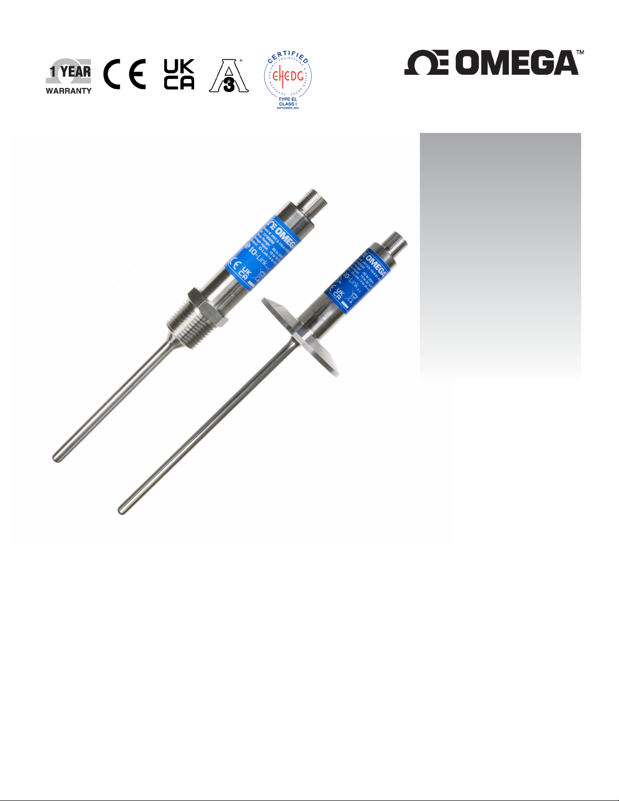
Sanitary PRTXS
User’s Guide
Shop online
at
omega.com
PRTXI model
e-mail: [email protected]
For latest product
manuals:
www.omega.com/en-
us/pdf-manuals
PRTXS model
PRTXI and PRTXS Series
RTD Temperature Transmitter with
IO-Link/Switch and 4 to 20 mA
Page 2

The information contained in this document is believed to be correct, but OMEGA accepts no liability for any errors it contains and reserves
the right to alter specifications without notice.
omega.com [email protected]
Omega Engineering, Inc:
Tel: (203) 359-1660
e-mail: [email protected]
Fax: (203) 359-7700
800 Connecticut Ave. Suite 5N01, Norwalk, CT 06854, USA
Toll-Free: 1-800-826-6342 (USA & Canada only)
Customer Service: 1-800-622-2378 (USA & Canada only)
Engineering Service: 1-800-872-9436 (USA & Canada only)
Omega Engineering,
Limited:
1 Omega Drive, Northbank,
Irlam Manchester M44 5BD
United Kingdom
Omega Engineering,
GmbH:
Daimlerstrasse 26 75392
Deckenpfronn Germany
2 | M5792
Page 3

Table of Contents
Table of Contents ............................................................................................................................................. 3
1 Notes, Cautions, and Warnings .................................................................................................................. 4
1.1 Requirements for Personnel .............................................................................................................................4
1.2 Designated Use ................................................................................................................................................4
1.3 Operational Safety ...........................................................................................................................................4
1.4 Product Safety .................................................................................................................................................4
2 Specifications ............................................................................................................................................ 5
3 PRTX Hardware Overview .......................................................................................................................... 9
3.1 Installation Instructions .................................................................................................................................. 10
3.1.1 Orientation ......................................................................................................................................................... 11
3.1.2 Device Temperature Ranges .............................................................................................................................. 11
3.1.3 Cylindrical Threads ............................................................................................................................................. 11
3.1.4 Tapered Threads ................................................................................................................................................. 12
4 Electrical Connection ............................................................................................................................... 13
4.1 IO-Link Operating Mode ................................................................................................................................. 13
4.2 4 to 20 mA Operating Mode ........................................................................................................................... 14
5 System Integration .................................................................................................................................. 15
5.1 Device and Vendor Identification .................................................................................................................... 15
5.2 Process Data .................................................................................................................................................. 15
5.3 Reading and Writing Device Data .................................................................................................................... 16
5.3.1 Specific Device Data ........................................................................................................................................... 16
5.3.2 IO-Link Specific Device Data ............................................................................................................................... 19
5.3.3 System Commands ............................................................................................................................................. 19
6 Diagnostics and Troubleshooting ............................................................................................................. 20
6.1 Diagnostic Information via Communication Interface ...................................................................................... 20
6.2 Diagnostic Overview ....................................................................................................................................... 21
.2.1 Device Behavior During an Event Fault .............................................................................................................. 22
6
6.3 Diagnostic List ................................................................................................................................................ 23
6.4 Event Logbook ............................................................................................................................................... 23
7 Maintenance and Cleaning ...................................................................................................................... 23
7.1 Services ......................................................................................................................................................... 23
8 Certifications and Approvals .................................................................................................................... 24
3 | M5792
Page 4

1 Notes, Cautions, and Warnings
If the equipment is used in a manner not specified in this manual, protection of the equipment may be impaired.
o not operate the equipment in flammable or explosive environments.
D
I
t is important to read and follow all precautions and instructions in this manual before operating or commissioning
this device as it contains important information relating to safety and EMC. Failure to follow all the safety precautions
may result in injury and/or damage to the equipment.
T
he following labels identify information that is especially important to note:
Note: Provides information that is important to successfully set up and use the PRTXI/PRTXS.
C
aution or Warning: Informs about the risk of electrical shock.
Caution, Warning, or Important: Informs of circumstances that can affect the functionality of the instruments and
must refer to accompanying documents.
1.1 Requirements for Personnel
Installation, commissioning, diagnostics, and maintenance must abide by the following requirements:
• Trained, qualified specialists must have relevant qualifications.
• Personnel must be authorized by the plant owner/operator.
• Personnel must be familiar with federal/national regulations.
• Before starting work, read and understand the instructions in the manual.
• Follow instructions and comply with basic conditions.
1.2 Designated Use
The device is a compact RTD temperature sensor for industrial temperature measurement. The manufacturer is
not liable for damage caused by improper or non-designated use.
1.3 Operational Safety
Modifications to the device: Unauthorized modifications to the device are not permitted and can lead to
Caution: Risk of injury!
• Operate the device only if it is in proper technical condition, free from errors and faults.
1.4 Product Safety
This measuring device is designed in accordance with safety requirements, has been tested, and shipped in a
condition in which it is safe to operate. It meets general safety standards and legal requirements. It also complies
with the EC directives listed in the EC Declaration of Conformity. The manufacturer confirms this by affixing the CE
mark to the device.
dangers to personnel and/or the device.
4 | M5792
Page 5
2 Specifications
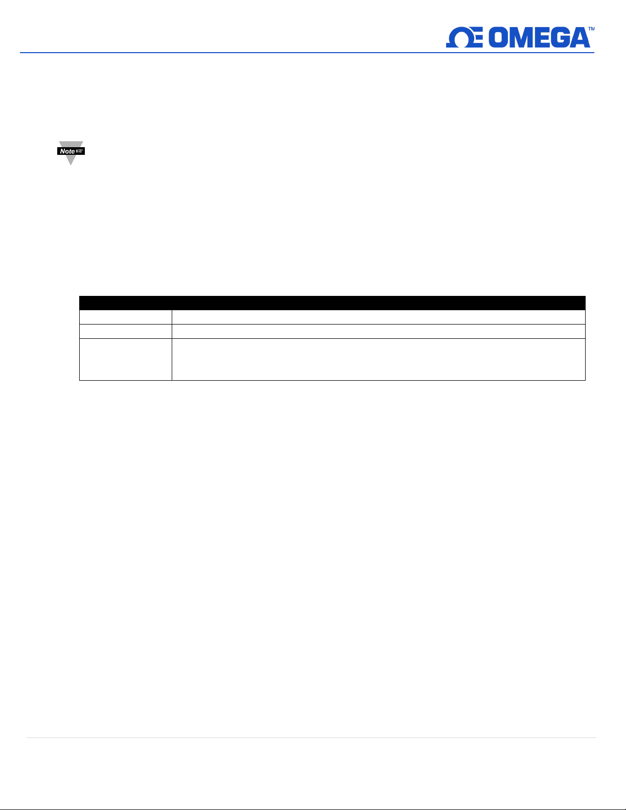
Fault
Description
Underranging
Linear drop from 4.0 to 3.8 mA.
Overranging
Linear increase from 20.0 to 20.5 mA.
≤ 3.6 mA (low) or ≥ 21 mA (high) can be selected. The high alarm setting can be set
of various control systems.
Measurement Range: -50 to 200°C (-58 to 392°F)
Output Signal
4 to 20 mA (Analog): 4 to 20 mA; measuring range -50 to 200°C (-58 to 392°F)
IO-Link (Digital): C/Q (IO-Link or switch output)
Note: For additional information regarding the IO-Link and 4 to 20 mA wiring, refer to Section 4 Electrical
Connection.
ailure Information
F
Failure information is generated if the measuring information is missing or not valid. The device displays the three
diagnostic messages with the highest priority.
In the IO-Link mode, the device transmits all failure information digitally.
n the 4 to 20 mA mode, the device transmits the failure information according to NAMUR NE43:
I
Failure (Sensor
Defective)
inearization/Transmission Behavior: Temperature – linear
L
P
ower Supply
Supply Voltage (IO-Link/4 to 20 mA): U
between 21.5 mA and 23 mA; providing the flexibility needed to meet the requirements
= 10 to 30 V DC, protected against reverse polarity. IO-Link communication is
b
guaranteed only if the supply voltage is at least 15 V. If the supply voltage is less
than 15 V, the device displays a diagnostic message and deactivates the switch
output.
Power Supply Failure: To meet electrical safety according to CAN/CSA-C22.2 No. 61010-1 or UL 61010-1, the device
may only be powered by a power supply unit with a limited energy electric circuit in accordance
with UL/EN/IEC 61010-1 chapter 9.4 or Class 2 according to UL 1310, "SELV or Class 2 circuit".
B
ehavior in the event of overvoltage (> 30 V): The device works continuously up to 35 V DC without
any damage. If the supply voltage is exceeded, the provided specifications can no longer be
guaranteed.
B
ehavior in the event of undervoltage:
If the supply voltage falls below the minimum value ~ 7 V, the device will switch off as if not supplied
with power.
ximum Current Consumption: ≤ 23 mA for 4 to 20 mA
Ma
Power-On Delay: 2 seconds
Overvoltage Protection: To protect against overvoltage in the power supply and signal/communication cables for the
RTD temperature sensor electronics, the use of a suitable surge arrester is recommended.
5 | M5792
Page 6
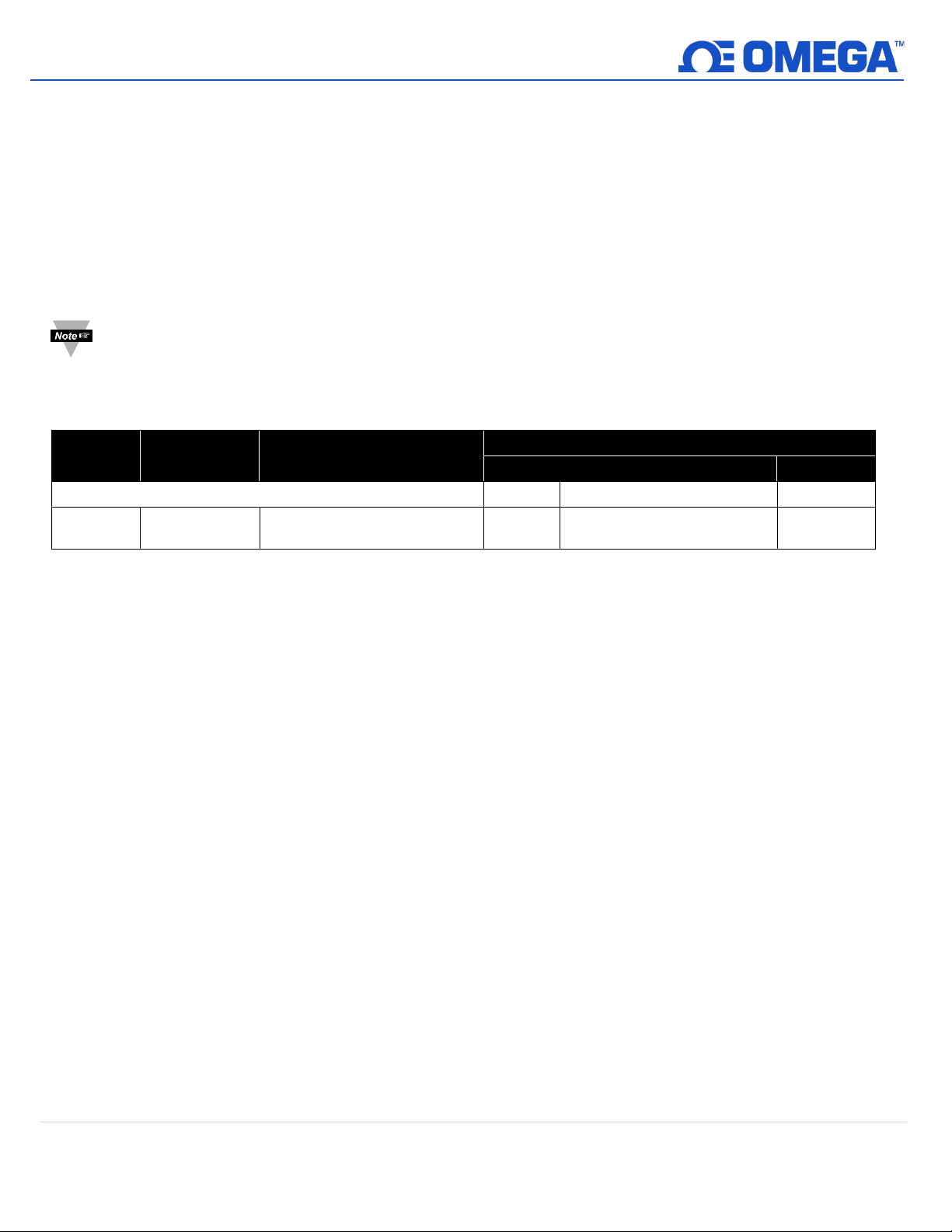
Reference Operating Conditions
Measured Error (±)
Digital
D/A 2)
Maximum
Based on measured value
≤0.55 °C
(0.99 °F)
ME = ± (0.215 °C (0.387 °F) +
0.134% * (MV - LRV))
djustment Temperature (Ice Bath): 0°C (32°F) for sensor
A
Ambient Temperature: (25°C ± 3°C (77°F ± 5°F) for electronics
Supply Voltage: 24 V DC ± 10%
Relative Humidity: <95%
Maximum Measured Error: When in accordance with the reference operating conditions listed above,
the measured error data corresponds to ±2 σ (Gaussian distribution). The
data include non-linearities and repeatability.
Measured error (according to IEC 60751) in °C = 0.15 + 0.002 |T|
Note: |T| = Numerical value of the temperature in °C without regard to algebraic sign.
TD Temperature Sensor with Electronics
R
Standard Designation Measuring Range
1)
IEC 60751 Pt100 Cl. A –50 to +200 °C (–58 to +392 °F)
1) Measured Value transmitted via IO-Link.
2) Percentages based on the configured span of the analog output signal.
M
V = Measured value
LRV = Lower range value of relevant sensor
Total measured error of transmitter at current output = √(Measured error digital² + Measured error D/A²)
0.05 % (8 µA)
6 | M5792
Page 7
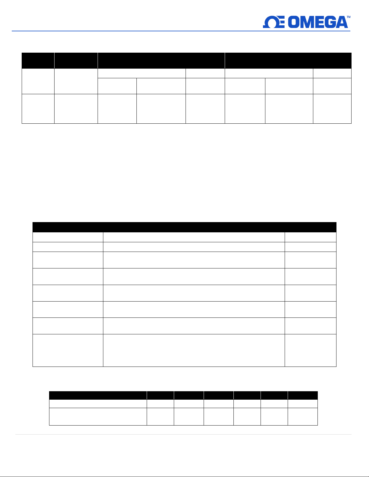
Operating Influences: The measured error data corresponds to ± 2 ρσ (Gaussian distribution).
Ambient Temperature Influence (+-) per 1 °C (1.8
°F) Change
Based on measured
value 4)
Based on
measured value 4)
°F)
0.004 % * (MV -
°F)
Sample Calculations
0.215 °C (0.387 °F) + 0.134% x [200 °C (392 °F) - (–50 °C (–58 °F))]
Measured Error D/A
0.05 % x 200 °C (392 °F)
0.10 °C (0.18 °F)
Influence of Ambient
Temperature (Digital)
(35 - 25) x (0.004 % x 200 °C (392 °F)), min. 0.008 °C (0.014 °F)
Influence of Ambient
Temperature (D/A)
(35 - 25) x (0.003 % x 200 °C (392 °F))
Influence of Supply
Voltage (Digital)
(30 - 24) x (0.004 % x 200 °C (392 °F)), min. 0.008 °C (0.014 °F)
Influence of Supply
Voltage (D/A)
(30 - 24) x (0.003 % x 200°C (392°F))
Measured Error Digital
Value (IO-Link)
√(Measured error digital² + Influence of ambient temperature
(digital)² + Influence of supply voltage (digital)²
√(Measured error digital² + Measured error D/A² + Influence of
Influence of supply voltage (D/A)²
1 Month
3 Months
6 Months
1 Year
3 Years
5 Years
Digital output IO-Link
± 9 mK
± 15 mK
± 19 mK
± 23 mK
± 28 mK
± 31 mK
Standard Designation
1)
Digital
Maximum 3)
0.010 °C (0.018
IE
C 60751
1) Measured value transmitted via IO-Link.
2) Percentages based on the configured span of the analog output signal.
3) Maximum measured error for the specified measuring range.
4) Deviations from maximum measured error possible due to rounding.
P
t100 Cl. A
MV = M
°F)
easured value
D/A 2) Digital 1) D/A 2)
0.004 % * (MV LRV), min.
0.008 °C (0.0144
0.003 % (0.48
µA)
Supply Voltage Influence (+-) per 1 V Change
3)
°F)
LRV), min.
0.008 °C (0.0144
aximum
M
0.010 °C (0.018
LRV = Lower range value of relevant sensor
Total measured error of transmitter at current output = √(Measured error digital² +
Measured error D/A²)
T
he following is a table of sample calculations with Pt100, measuring range -50 to +200 °C (-58 to +392°F), ambient
temperature +35 °C (+95 °F), and supply voltage 30 V:
0.003 % (0.48
µA)
Measured Error Digital
Measured Error Analog
Value (Current Output)
ong-Term Drift:
L
ambient temperature (digital)² + Influence of ambient
temperature (D/A)² + Influence of supply voltage (digital)² +
0.55 °C (0.99 °F)
0.08 °C (0.14 °F)
0.06 °C (0.11 °F)
0.05 °C (0.09 °F)
0.04 °C (0.07 °F)
0.56 °C (1.01 °F)
0.57 °C (1.03 °F)
Current output 4-20 mA ± 2.5 µA ± 4.3 µA ± 5.4 µA ± 6.4 µA ± 8.0 µA ± 8.8 µA
7 | M5792
Page 8

Response Time T90: Test in water at 0.4 m/s (1.3 ft/s) according to IEC 60751; temperature changes in increments of
Design
t
10 K.
90
1/8” diameter probe 2 s
3/16” diameter probe 2 s
1/4” diameter probe 4 s
ironment
Env
Ambient Temperature Range: -40 to 85°C (-40 to 185°F)
Storage Temperature: -40 to 85°C (-40 to 185°F)
Operating Altitude: Up to 2000 m (6600 ft) above sea level
Climate Class: As per IEC/EN 60654-1, Class Dx
Degree of Protection: As per IEC/EN 60529 IP69
Shock and Vibration Resistance: The RTD temperature sensor meets the requirements of IEC
60751, which specifies shock and vibration resistance of 5 g in the
10 to 2000 Hz range.
Ele
ctromagnetic Compatibility (EMC): EMC in accordance with all the relevant requirements of the IEC/EN
61326 series and NAMUR Recommendation EMC (NE21). For details, refer to the
Declaration of Conformity.
• Maximum measured error under EMC tests: < 1 % of the span
• Interference immunity according to IEC/EN 61326 series, requirements for
industrial fields.
• Interference emission according to IEC/EN 61326 series, Class B equipment
IO-Li
nk
• Only the requirements of IEC/EN 61131-9 are met in IO-Link mode.
• The connection between the IO-Link master and RTD temperature sensor is established using an unshielded 3- wire
cable, maximum 20 m (65.6 ft) in length.
o 20 mA
4 t
• Electromagnetic compatibility in accordance with all the relevant requirements of the IEC/EN 61326 series and NAMUR
Recommendation EMC (NE21).
• With a connection cable length of 30 m (98.4 ft): always use a shielded cable.
• The use of twisted pair shielded connection cables is generally recommended.
ectrical Safety: Protection class III, Overvoltage category II, Pollution level 2
El
8 | M5792
Page 9
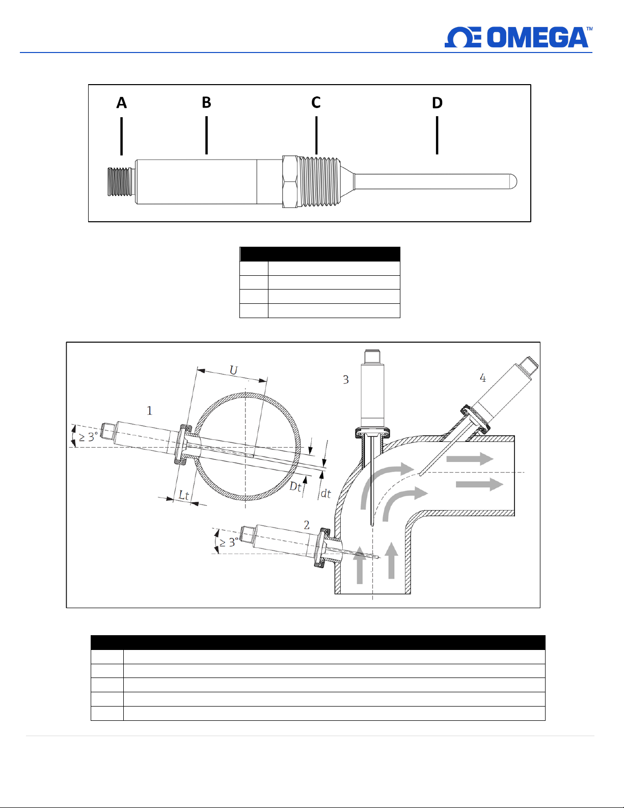
3 PRTX Hardware Overview
Key
Description
1
Perpendicular to flow direction, installed at a minimum angle of 3° to ensure self-draining
2
Perpendicular to flow direction, installed at a minimum angle of 3° to ensure self-draining
3
On elbows
4
Inclined installation in pipes with a small nominal diameter
U
Immersion length
Key
Description
A
M12 threaded connector
B
Transmitter housing
C
Process connection
D
Sensor Probe
Figure 1: PRTX probe diagram
Figure 2: Installation visual diagram guide
9 | M5792
Page 10

3.1 Installation Instructions
The immersion length of the RTD temperature sensor can considerably influence the accuracy of the device. If the
immersion length is too short, measurement errors can occur. When installing the device in a pipe, the immersion
length should penetrate halfway into the pipe diameter and ideally also be at least 15 times the diameter of the
probe. Installation examples include:
• Pipes
• Tanks
• Other plant components
roceed as follows to install the device:
P
Step 1: The permitted tightening torque of the process connections can be found in the specifications.
Step 2: The process connection and compression fitting must comply with the maximum specified process
pressure.
Step 3: Make sure that the device is installed and secured before applying the process pressure.
Step 4: Adjust the tightening torque of the thermowell to the process conditions.
Step 5: It may be necessary to calculate the static and dynamic tightening torque.
I
n the case of pipes with a small nominal diameter, the tip of the RTD temperature sensor should be inserted deep
enough into the process so that it extends past the pipe axis; Installation at an angle (4) may be another solution.
When determining the immersion length or installation depth, parameters of the RTD temperature sensor and of
the medium to be measured, such as flow velocity and process pressure, must be considered.
N
ote: The requirements of the EHEDG and the 3-A Sanitary Standard must be adhered to.
• Installation instructions EHEDG/cleanability: Lt ≤ (Dt-dt)
• Installation instructions 3-A/cleanability: Lt ≤ 2(Dt-dt)
• EHEDG certified installation requires the use of special gaskets as described in the EHEDG position
paper “Easy cleanable pipe couplings and process connections” Version 5, June 2019
he following actions must be taken if a sealing ring (O-ring) or seal fails:
T
S
tep 1: The RTD temperature sensor must be removed.
Step 2: The thread and the O-ring joint/sealing surface must be cleaned.
Step 3: The sealing ring or seal must be replaced.
Step 4: Proper cleaning of the device must be performed after installation.
I
n the case of weld-in connections, exercise the necessary degree of care when performing the welding work on
the process side:
tep 1: Use suitable welding material.
S
Step 2: Flush-weld or weld with welding radius ≥ 3.2 mm (0.13 in).
Step 3: Avoid crevices, folds or gaps.
Step 4: Ensure the surface is honed and polished, Ra ≤ 0.76 µm (30 µin).
he installed sensor is suitable for cleaning in place. Cleaning is performed together with the pipe or tank. In the
T
case of internal tank fixtures using process connection nozzles, it is important to ensure that the cleaning assembly
directly sprays this area so that it is cleaned properly.
10 | M5792
Page 11
3.1.1 Orientation
G ¼”
61 Nm (45 ft/lbs)
G 3/8”
75 Nm (55 ft/lbs)
G ½”
G ¼”
CSW-1/4
G 3/8”
CSW-3/8
G ½”
CSW-1/2
No restrictions. However, the process must be able to self-drain. If there is an opening to detect leaks at the
process connection, the opening must be at the lowest possible point.
3.1.2 Device Temperature Ranges
The device generates a diagnostic message S825 if unfavorable device conditions are reached, such as high
process temperature, high ambient temperature, or electronics too close to the process. The device
generates diagnostic message F001 or Failure Current if the device temperature exceeds the recommended
temperature.
A
mbient Temperature Range: -40 to 85°C (-40 to 185°F) The RTD temperature sensor electronics must be
protected against temperatures over 85°C (185°F)
rocess Temperature Range: -50 to 200°C (-58 to 392°F)
P
3.1.3 Cylindrical Threads
Note: Seals must be used for cylindrical G threads.
Process Connection Tightening Torque [Nm]
81 Nm (60 ft/lbs)
f new sealing washers are required, they can be purchased from Omega Engineering in the following sizes:
I
Process Connection Omega Part Number
11 | M5792
Page 12

3.1.4 Tapered Threads
¼” NPT
Hand-tighten, then, 2-3 full turns
⅜” NPT
Hand-tighten, then, 2-3 full turns
½” NPT
The operator must verify if additional sealing is necessary in the case of NPT threads or other tapered
threads.
Process Connection Tightening Torque [Nm]
Hand-tighten, then, 2-3 full turns
Figure 3: Tapered thread measurement guide
12 | M5792
Page 13
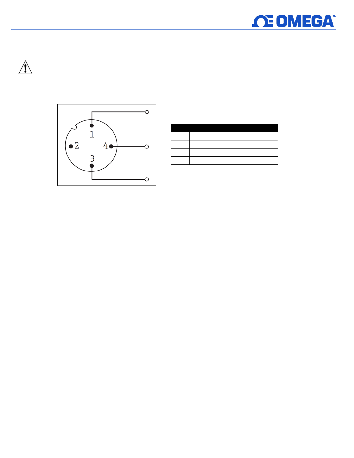
4 Electrical Connection
Pin
Description
1
+ Power supply 15 to 30 V DC
2
Not used
3
- Power supply 0 V DC
4
C/Q (IO-Link or switch output)
The Omega PRTX offers two operating modes. Refer to the wiring diagrams below outlining the two different options.
Important: Do not overtighten the M12 plug, as this may damage the device. The maximum torque of the M12
knurl is 0.4 Nm. The indicated degree of protection is ensured if the M12x1 cable connector meets the
required degree of tightness.
4.1 IO-Link Operating Mode
Figure 3: IO-Link wiring diagram
Switching Capacity
• 1x PNP switch output
• Switch state ON Ia ≤ 200 mA; switch state OFF Ia ≤ 10 µA
• Switch cycles > 10,000,000
• Voltage drop PNP ≤ 2 V
• Overload protection
• Automatic load testing of switching current
• If a current of over 220 mA flows in the ON switch state, the device switches to a safe state
• Diagnostic message Overload at switch output
• Switch functions
• Hysteresis or window function
• NC contact or NO contact
• No pull-down resistor is integrated in the device for the switch output
13 | M5792
Page 14
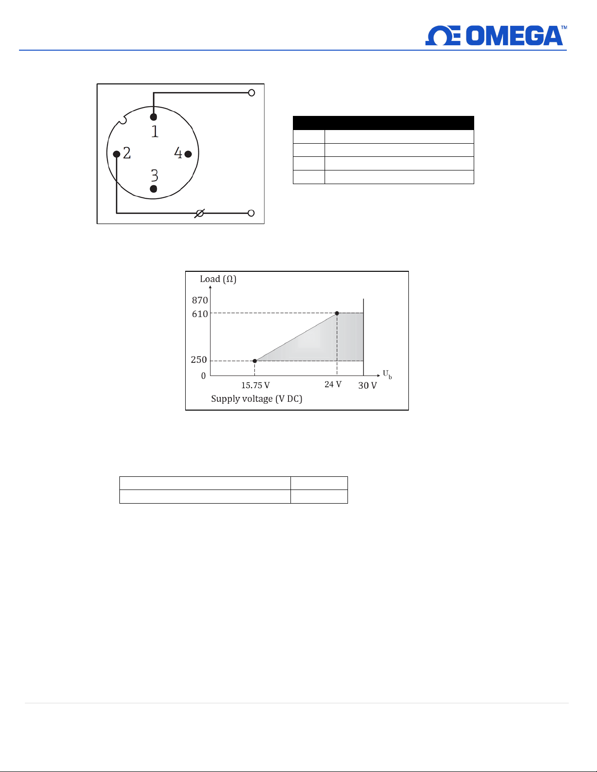
4.2 4 to 20 mA Operating Mode
Pin
Description
1
+ Power supply 10 to 30 V DC
2
- Power supply 0 V DC
3
Not used
4
Not used
Configurable Sensor Input Damping
0 to 120 s
Factory Default Setting
0 s
Figure 4: 4 to 20 mA wiring diagram
Load: R
inearization/Transmission Behavior: Temperature – Linear
L
D
amping:
b max
= (U
– 10 V) / 0.023 A (current output)
b max
Figure 5: Maximum allowable load resistance
14 | M5792
Page 15
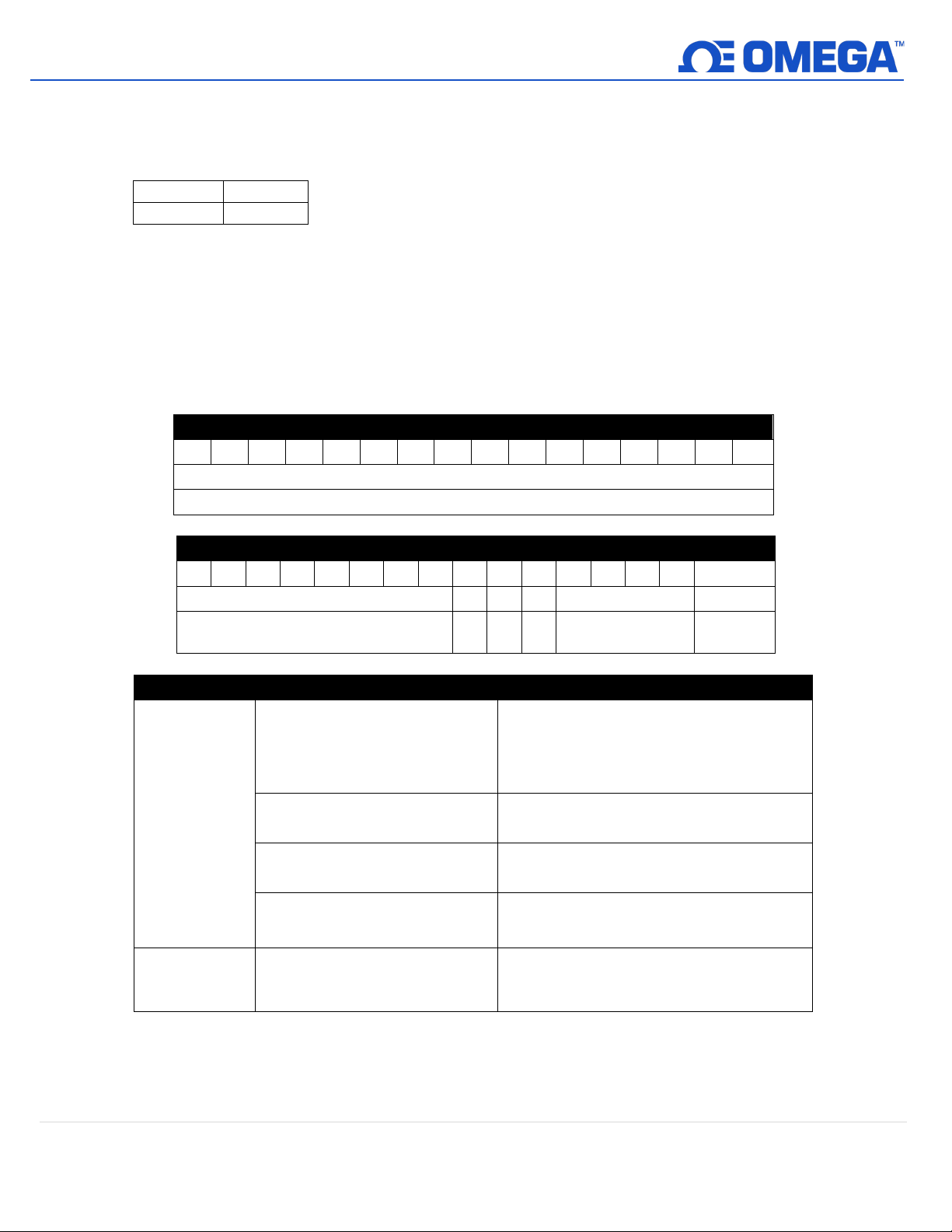
5 System Integration
Device ID
8585472
Vendor ID
1590
Byte 3
Byte 4
15
14
13
12
11
10 9 8 7 6 5 4 3 2 1 0
sint8
Enum4
Bool
Measured value
status
Switch
state
Process Value
Values
Meaning
The transmitted measured value must be
0.1)
Byte 1
Byte 2
31
30
29
28
27
26
25
24
23
22
21
20
19
18
17
16
Temperature (with one decimal place)
5.1 Device and Vendor Identification
5.2 Process Data
When the PRTX is in Digital Mode, the state of the switch output and the temperature value are transmitted in
the form of process data via IO-Link. The signal is initially transmitted in the SIO-Mode (Standard IO-Mode).
Digital IO-Link communication starts as soon as the IO-Link master sends the Wake-Up command.
• In SIO mode, the switch output is switched at pin 4 of the M12 connector. In the IO-Link communication
mode, this pin is reserved for communication.
• The measuring device's process data are transmitted cyclically in 32-bit batches.
sint16
Scale (-1)
–32000 to +32000
Temperature
Scale -1
32764 = No measurement data
- 32760 = Out of range (-)
32760 = Out of range (+)
Temperature value with one decimal place
Example: a transmitted value of 123
corresponds to a measured temperature
value of 12.3 °C
Process value if no valid measured value is
available
Process value if the measured value is
below the lower limit value
Process value if the measured value is
above the upper limit value
multiplied by 10 exp (Scale) (times 10-1 or
15 | M5792
Page 16
Process value
Values
Meaning
value
0 = Bad
Measured value cannot be used
1 = Uncertain
Measured value can only be used to a
outside the permitted range (S825)
Measured value can only be used to a
measured variable is active (C485)
3 = Good
Measured value is good
Measured value without limit value
violation
1 = Low limited
Limit value violation at lower end
2 = High limited
Limit value violation at upper end
0 = Off
Switch output opened
1 = On
Switch output closed
Index
(dec)
Index
(hex)
Size
(byte)
Data
Storage
Application
Specific Tag
Order Code
1054
0x041E
20
String
r/- – –
–
Extended
Order Code
32 = °C
35 = K
Damping
7271
0x1C67
1
UInteger8
r/w
0 s
0 to 120 s
Yes
–10 to +10 °C
(–18 to +18 °F)
Window normally
Hysteresis normally
Hysteresis normally
Off (0x80EC)
Measured
status [bit 4 - 3]
2 = Manual/Fixed
0 = Not limited
Measured value
status
[bit 2- 1]
3 = Constant Measured value is set to a constant value
Switch output
[bit 0]
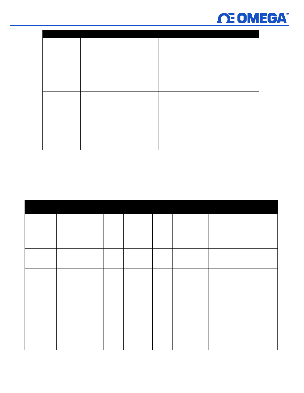
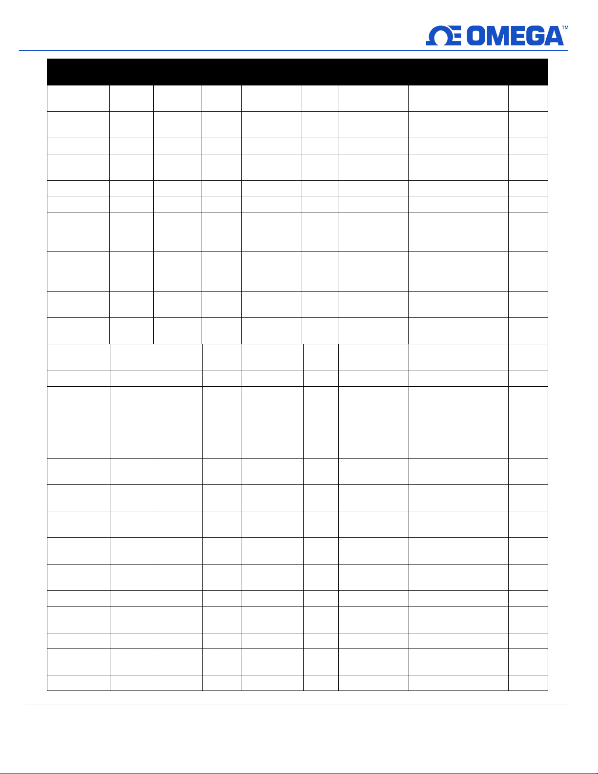
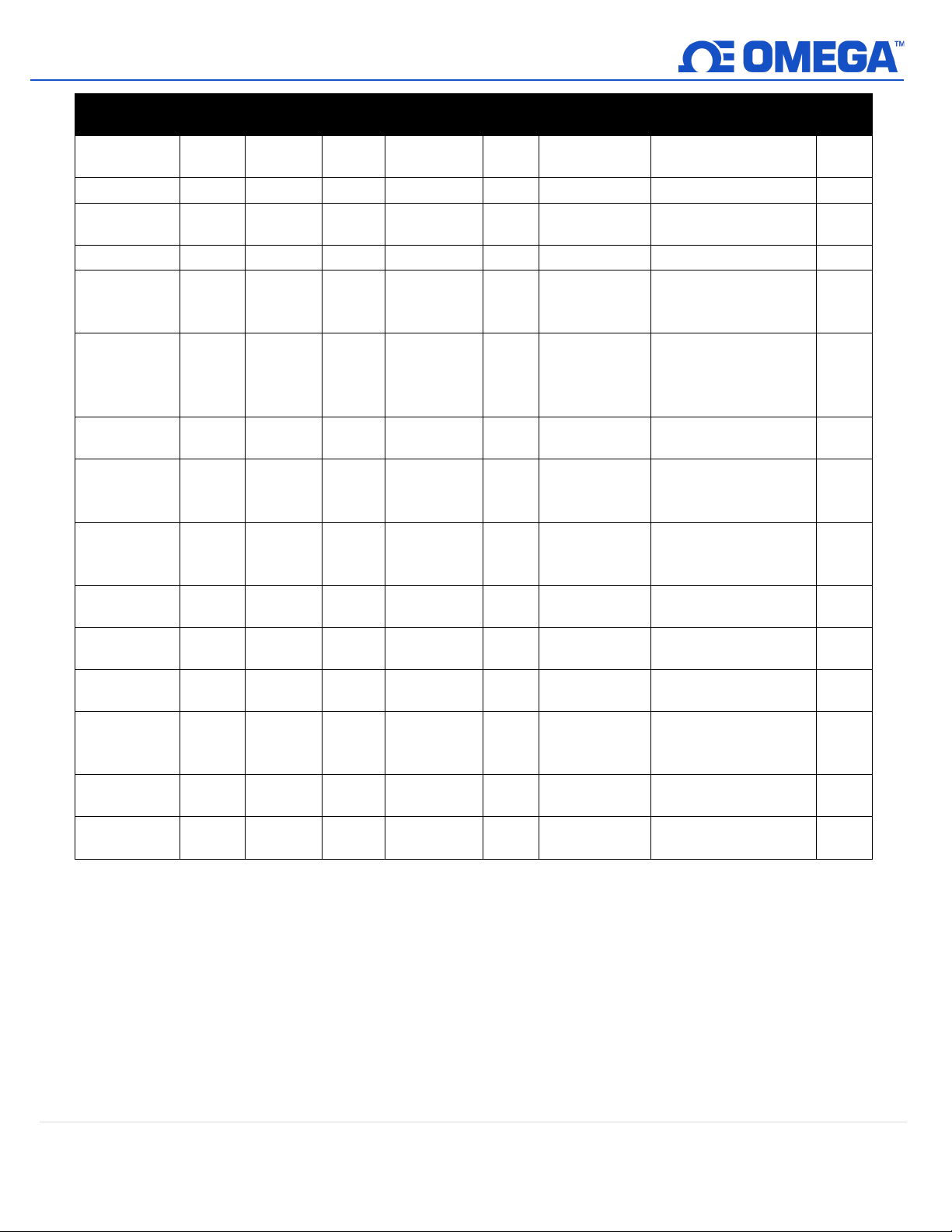
5.3 Reading and Writing Device Data
Device data are always exchanged acyclically and at the request of the IO-Link master via the ISDU communication
channel. The IO-Link master can read the following parameter values or device conditions:
5.3.1 Specific Device Data
The default values apply to parameters which are not ordered with customer-specific settings.
limited extent, e.g.: device temperature is
limited extent, e.g.: simulation of the
Identifier
Unit 5121 0x1401 1 UInteger8 r/w 32
Sensor Offset 3082 0x0C0A 4 Float r/w 0 °C (32 °F)
Operating
Mode Switch
Data Type Access Default Value Value Range
24 0x0018 32 String r/w – – Yes
259 0x0103 60 String r/- – – –
33 = °F
open (0x0CFF)
Window normally
2050 0x0802 2 UInteger16 r/w
Hysteresis
normally open
(0x0C9C)
closed (0x0C96)
open (0x0C9C)
closed (0x0C99)
Yes
Yes
Yes
16 | M5792
Page 17
Identifier
Index
(dec)
Index
(hex)
Size
(byte)
Data
Storage
Switch Point
Value
Switchback
Point Value
2052
0x0804
4
Float
r/w
90 °C (194 °F)
-1E+20 to 1E+20
Yes
Switch Delay
2053
0x0805
1
UInteger8
r/w
0 s
0 to 99 s
Yes
Switchback
Delay
20 mA Value
8219
0x201B
4
Float
r/w
200 °C (392 °F)
–50000 to +50000 °C
Yes
Current
4 mA
Current
20 mA
0 = Low alarm
2 = High alarm
Failure
Current
Operating
Time
Alarm Delay
6147
0x1803
1
UInteger8
r/w
2 s
1 to 5 s
Yes
0: Device is OK
4: Failure
Detailed
Device Status
In accordance with
IO-Link specification
Actual
Diagnostic 1
Actual
Diagnostic 2
Actual
Diagnostic 3
Previous
Diagnostics 1
Previous
Diagnostics 2
Timestamp 2
6205
0x183D
4
UInteger32
r/-
–
–
–
Previous
Diagnostics 3
Timestamp 3
6206
0x183E
4
UInteger32
r/-
–
–
–
Data Type Access Default Value Value Range
2051 0x0803 4 Float r/w 100 °C (212 °F) -1E+20 to 1E+20 Yes
2054 0x0806 1 UInteger8 r/w 0 s 0 to 99 s Yes
4 mA Value 8218 0x201A 4 Float r/w -50 °C (-58 °F) –50000 to +50000 °C Yes
Trimming
Trimming
8213 0x2015 4 Float r/w 4.00 mA 3.85 to 4.15 mA Yes
8212 0x2014 4 Float r/w 20.00 mA 19.85 to 20.15 mA Yes
Failure Mode 8234 0x202A 1 UInteger8 r/w 0 = Low alarm
8232 0x2028 4 Float r/w 22.5 mA 21.5 to 23 mA Yes
6148 0x1804 4 UInteger32 r/- – – Yes
Device Status 36 0x0024 1 UInteger8 r/- –
37 0x0025 36 OctetString r/- –
6184 0x1828 2 UInteger16 r/- – – –
1: Maintenance
required
2: Out of specification
3: Functional check
Yes
–
–
Timestamp 1 6204 0x183C 4 UInteger32 r/- – – –
6186 0x182A 2 UInteger16 r/- – – –
6188 0x182C 2 UInteger16 r/- – – –
6214 0x1846 2 UInteger16 r/- – – –
6216 0x1848 2 UInteger16 r/- – – –
6218 0x184A 2 UInteger16 r/- – – –
17 | M5792
Page 18
Identifier
Index
(dec)
Index
(hex)
Size
(byte)
Data
Storage
Previous
Diagnostics 4
Timestamp 4
6207
0x183F
4
UInteger32
r/-
–
–
–
Previous
Diagnostics 5
Timestamp 5
6208
0x1840
4
UInteger32
r/-
–
–
–
Current
Simulation
Current
Value
Sensor
Simulation
0 = Off
1 = On
Sensor
Value
0 = Disabled
33006 = On
Sensor Min
Value
Sensor Max
Value
Device
Temperature
Device
Min
Device Temp
Max
MDC
Descriptor
Data Type Access Default Value Value Range
6220 0x184C 2 UInteger16 r/- – – –
6222 0x184E 2 UInteger16 r/- – – –
Output
Output
Simulation
Simulation
Switch Output
Simulation
8210 0x2012 2 UInteger16 r/w 33004 = Off
33004 = Off
33005 = On
8211 0x2013 4 Float r/w 3.58 mA 3.58 to 23 mA –
3109 0x0C25 1 UInteger8 r/w 0 = Off
3104 0x0C20 4 Float r/w 0 °C (32 °F) -1E+20 to 1E+20 °C –
2056 0x0808 2 UInteger16 r/w 0 = Disabled
33004 = Off
3081 0x0C09 4 Float r/- – – –
3080 0x0C08 4 Float r/- – – –
4096 0x1000 4 Float r/- – – –
–
–
–
Temperature
4107 0x100B 4 Float r/- – – –
4106 0x100A 4 Float r/- – – –
16512 0x4080 11 Record r/- – – –
18 | M5792
Page 19
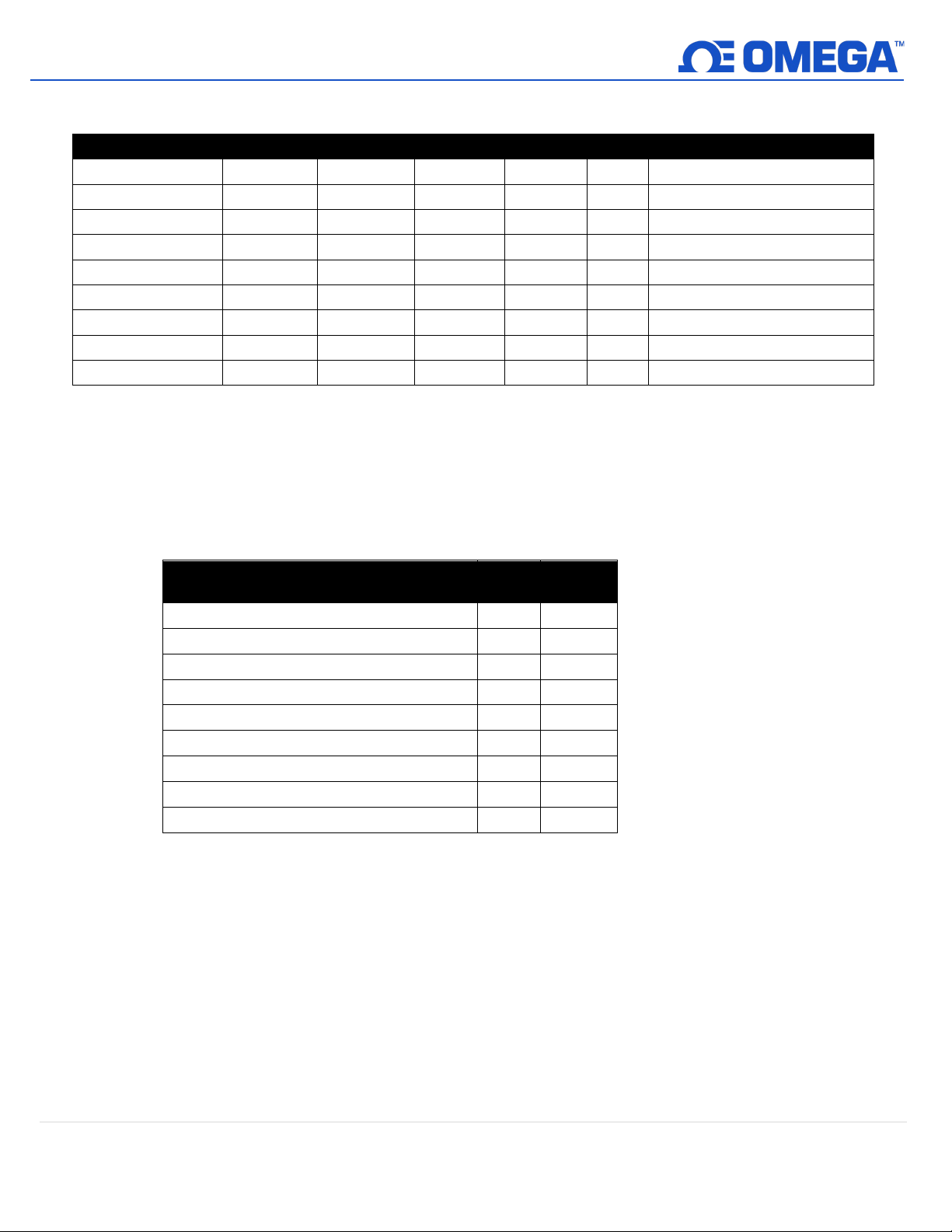
5.3.2 IO-Link Specific Device Data
Identifier
Index (dec)
Index (hex)
Size (byte)
Data Type
Access
Default Value
Serial Number
21
0x0015
16
String
r/- – Product ID
19
0x0013
32
String
r/-
PRTXI-PRTXS
Product Text
20
0x0014
32
String
r/-
PRTXI-PRTXS
Vendor Name
16
0x0010
32
String
r/-
Omega Engineering
Vendor Text
17
0x0011
32
String
r/-
Sensing Incredible Things
Hardware Version
22
0x0016
8
String
r/-
–
Firmware version
23
0x0017
8
String
r/-
–
Value
(dec)
Value
(hex)
Reset factory settings
130
0x82
Activate parametrization lock
160
0xA0
Deactivate parametrization lock
161
0xA1
Reset sensor min/max values
162
0xA2
IO-Link 1.1 system test command 240
240
0xF0
IO-Link 1.1 system test command 241
241
0xF1
IO-Link 1.1 system test command 242
242
0xF2
IO-Link 1.1 system test command 243
243
0xF3
Product Name 18 0x0012 32 String r/- PRTX RTD Temperature Sensor
Device Access Locks 12 0x000C 2 Record r/w –
5.3.2.1 IO-Link Configuration
IO-Link functions and device-specific parameters are configured through the device’s IO-Link
communication. IO-Link devices are typically configured using the automation system. The PRTX
supports IO-Link Data Storage.
5.3.3 System Commands
Identifier
Reset device temperature min/max values 163 0xA3
19 | M5792
Page 20
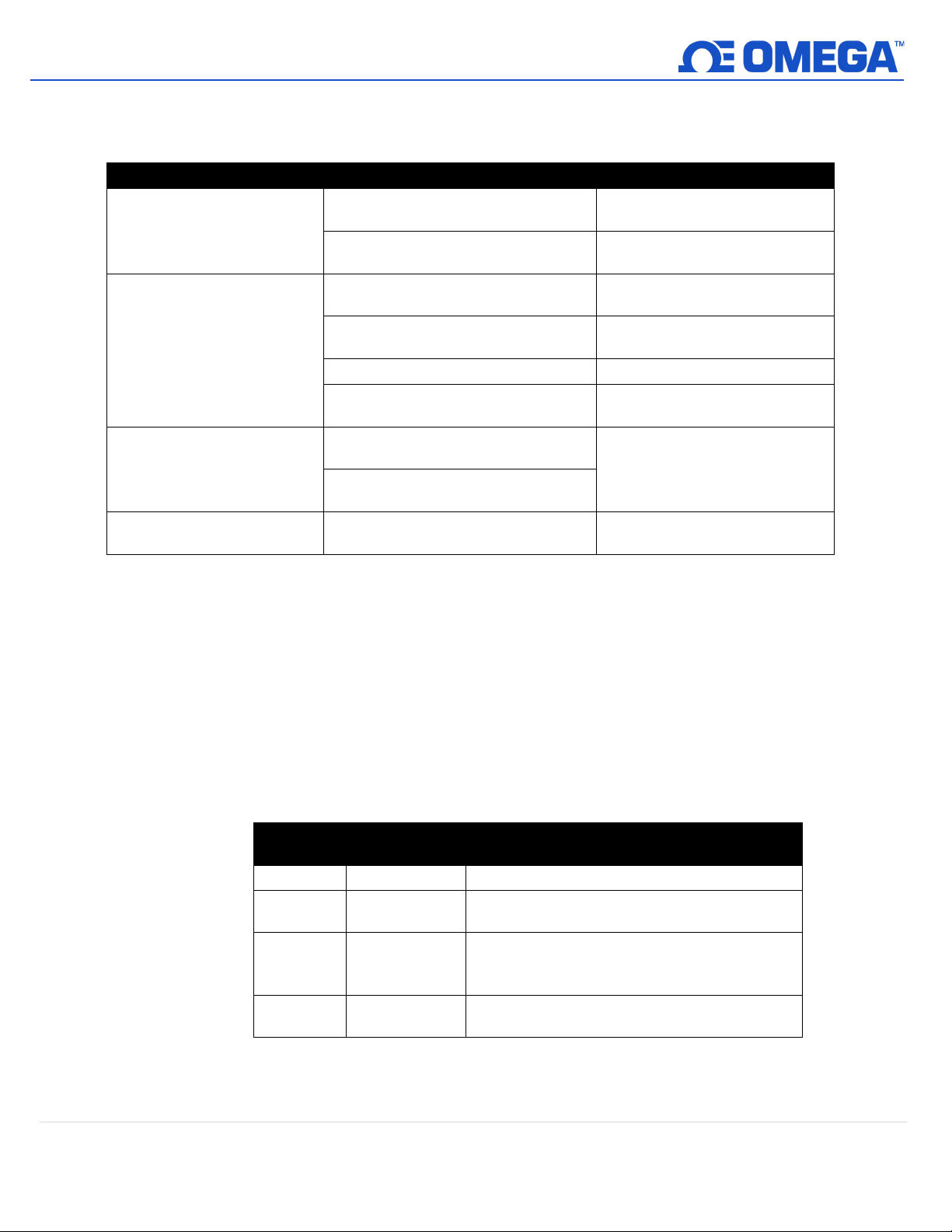
6 Diagnostics and Troubleshooting
Error
Possible Cause
Solution
Supply voltage does not match the
value indicated in the specifications.
The polarity of the supply voltage is
wrong.
Correct the polarity of the
supply voltage.
The device has been incorrectly
configured.
Check and correct the
parameter configuration.
The device has been incorrectly
connected.
Incorrect device orientation.
Install the device correctly.
Heat dissipation over the measuring
point.
Observe the installed length of
the sensor.
Communication cable is not
connected.
Communication cable is incorrectly
attached to the IO-Link master.
No transmission of process
data
Correct errors that are
displayed as a diagnostic event.
Alphabetic
Character
F
Operating error
An operating error has occurred.
The device is in service mode (e.g. during a
simulation).
The device is being operated outside its
technical
cleaning processes).
Maintenance
required
Maintenance is required.
Follow these instructions to resolve general troubleshooting issues.
Device is not responding.
Apply correct voltage.
Device measures incorrectly.
No communication
There is an error in the device.
6.
1 Diagnostic Information via Communication Interface
The Device Status parameter shows the event category of the active diagnostic message with the highest priority.
e status signals provide information on the state of the device by categorizing the cause of the diagnostic
Th
information. The status signals are categorized according to NAMUR Recommendation NE 107:
F = Failure,
C = Function Check
S = Out of Specification
M = Maintenance Required
Check the pin assignment.
Check wiring and cables.
Event Category Meaning
C Service mode
S
M
Out of
specification
specifications (e.g. during warm-up or
20 | M5792
Page 21

6.2 Diagnostic Overview
IO-Link
Qualifier
IO-Link
Code
The sensor is defective
sensor short-circuit)
1: Check sensor.
conditions.
IO-Link
Notification
Factory reset
active
Factory reset is active,
please wait.
Initialization
active
Initialization active,
please wait.
Simulation of the
active
IO-Link
Warning
Current output
simulation active
Simulation of the
current output is active
/IO-Link
Warning
Switch output
simulation active
Simulation of the
switch output is active
Current range is invalid
difference between
greater than or equal to
10°C.
Switch points are
switchback point.
IO-Link
Warning
Supply voltage
too low
Increase supply
voltage.
1: Increase load
3: Replace device.
of the electronics out of
1: Check ambient
temperature.
Diagnostic
Message
Diagnostic
Behavior
Event
Event
Event Text Reason Corrective Measure
F001 Alarm IO-Link Error 0x1817 Device failure Device fault
F004 Alarm IO-Link Error 0x1818 Sensor defective
S047 Warning
C401 Warning
IO-Link
Warning
0x1819
0x181F
Sensor limit
reached
C402 - - -
C485 Warning
C491 Warning
C494 Warning
IO-Link
Warning
0x181A
0x181B
0x181C
Process variable
simulation active
(e.g.: sensor failure or
Sensor limit has been
reached
Factory reset is active
Initialization is active
process variable is
1: Restart the device.
2: Replace device.
Replace device.
2: Check process
Deactivate simulation.
Deactivate simulation.
Deactivate simulation.
F537 Alarm IO-Link Error 0x181D
S801 Warning
0x181E
S804 1) Alarm - -
S825 Warning
IO-Link
Warning
0x1812
Configuration
invalid
Overload at
switch output
Operating
temperature
The
the 4mA value and
20mA value must be
invalid. The switch
point must be greater
than or equal to the
Supply voltage too low
Overload at the switch
output
Operating temperature
specification
1: Check device
configuration.
2: U
pload and
download new
configuration.
resistance at switch
output.
2: Check the output.
temperature.
2: Check process
21 | M5792
Page 22

Diagnostic
IO-Link
Code
Message
S844 2) Warning - -
1) Diagnostic only possible in SIO mode
2) Diagnostic only possible in the 4 to 20 mA mode
Diagnostic
Behavior
IO-Link
Event Qualifier
Event
Event Text Reason Corrective Measure
Process value out
of specification
6.2.1 Device Behavior During an Event Fault
The diagnostic behavior of the device differs depending on the selected operating mode. Regardless of the
operating mode, all the diagnostic messages are saved in the event logbook, where they can be accessed as
required.
6.2.1.1 IO-Link
The device displays warnings and faults via IO-Link. All the device warnings and faults are for
information purposes only and do not have a safety function. The errors diagnosed by the device are
displayed via IO-Link in accordance with NE107. A distinction must be made between the following
types of diagnostic behavior:
Wa
rning
The device continues measuring in the event of warning-type diagnostic behavior. The output signal is
not affected (exception: simulation of the process variable is active).
Process value is outside
the specification
1: Check process
value.
2: Check application.
3: Check sensor.
A
larm
• The device does not continue measuring if this type of error occurs. The output signal adopts its
fault state value in the event of an error.
• The PDValid Flag indicates that the process data are invalid.
• The fault state is displayed via IO-Link.
6
.2.1.2 Switch output
Warning
The switch output remains in the state defined by the switch points.
larm
A
The switch output changes to the open state.
6.2.1.3 4 to 20 mA
Warning
The current output is not affected.
A
larm
The current output adopts the configured failure current.
Note: The behavior of the output in the event of a failure is regulated in accordance with NAMUR NE43.
• The failure current can be set.
• The selected failure current is used for all errors.
22 | M5792
Page 23
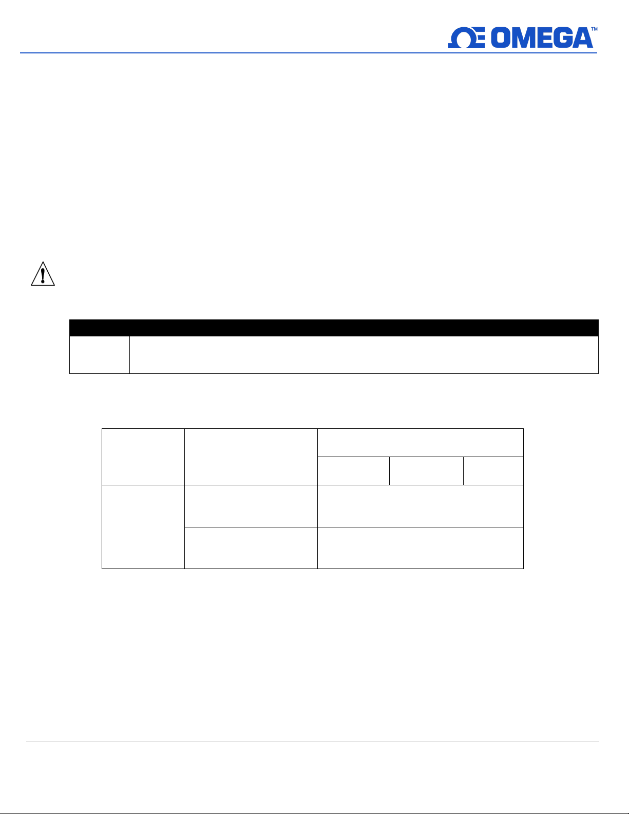
6.3 Diagnostic List
Service
Description
Standard Calibration Points for CAL-3
Probe Diameter
0.125 in
(3.18 mm)
0.188 in
(4.76 mm)
0.250 in
(6.35 mm)
0°C (32°F)
100°C (212°F
100°C (212°F)
200°C (392°F)
If three or more diagnostic events are pending simultaneously, only the 3 diagnostic messages with the highest
priority are shown in the diagnostic list. The status signal dictates the priority in which the diagnostic messages are
displayed. The following order of priority applies: F, C, S, M. If two or more diagnostic events with the same status
signal are active simultaneously, the numerical order of the event number dictates the order of priority in which
the events are displayed, e.g. F042 appears before F044 and before S044.
6.4 Event Logbook
The diagnostic messages are shown in chronological order in the event logbook. Additionally, a timestamp is saved
with every diagnostic message. This timestamp is determined by the operating time counter.
7 Maintenance and Cleaning
The device must be cleaned whenever necessary. Cleaning can also be done when the device is installed. When
cleaning the device, care must be taken to ensure that it is not damaged.
Important: Avoid damage to the device and the system. Pay attention to the specific IP code when cleaning.
7.1 Services
Calibration
alibration: Factory calibration is available upon request. Customers may request Cal-3 for standard 3-point
C
calibration, or Cal-4 for user-specified temperature points. All calibrations are NIST traceable.
RTD elements may drift depending on the application. Regular recalibration to verify accuracy is
recommended. The calibration can be performed by Omega Engineering.
Probe Type Probe Length Minimum
< 178 mm (7”)
RTD
≥ 178 mm (7”)
50°C (122°F)
150°C (302°F)
23 | M5792
Page 24

8 Certifications and Approvals
CE Mark: The product meets the requirements of the harmonized European standards. As such, it complies with the
legal specifications of the EC directives. The manufacturer confirms successful testing of the product by
affixing the CE-mark.
UKCA Mark: The product meets the requirements of UK designated standards. As such, is complies with the
specifications of relevant UK legislations. The manufacturer confirms successful testing of the product by
affixing the UKCA mark.
oHS: The measuring system complies with EU Directive 2011/65/EU (RoHS 2) and 2015/863 of the European
R
Parliament on the restriction of use of certain hazardous substances in electrical and electronic equipment.
M
TBF: For the transmitter: 327 years, according to Siemens Standard SN29500
ygienic Standard (Applies to Sanitary Models Only):
H
• 3-A Authorization No. 1519, 3-A Sanitary Standard 74-07. Sensors and Sensor Fittings and Connections.
• EHEDG Certified, Certificated No. EHEDG-C2200048
Other Standards and Guidelines:
• Degree of protection provided by enclosures (IP code) according to IEC 60529
• Safety requirements for electrical equipment for measurement, control and laboratory use according to IEC 61010-
1
• Industrial platinum resistance RTD temperature sensor in accordance with IEC 60751
• Electromagnetic compatibility (EMC requirements) IEC/EN 61326 series
• NAMUR International user association of automation technology in process industries (www.namur.de)
• NE21 - Electromagnetic Compatibility (EMC) of Industrial Process and Laboratory Control Equipment.
• NE43 - Standardization of the Signal Level for the Failure Information of Digital Transmitters.
• Electromagnetic compatibility (EMC) according to IO-Link Specification IEC 61131-09
24 | M5792
Page 25

WARRANTY/DISCLAIMER
OMEGA ENGINEERING, INC. warrants this unit to be free of defects in materials and workmanship for a
period of 13 months from date of purchase. OMEGA’s WARRANTY adds an additional one (1) month
grace period to the normal one (1) year product warranty to cover handling and shipping time. This
ensures that OMEGA’s customers receive maximum coverage on each product.
If the unit malfunctions, it must be returned to the factory for evaluation. OMEGA’s Customer Service
Department will issue an Authorized Return (AR) number immediately upon phone or written request.
Upon examination by OMEGA, if the unit is found to be defective, it will be repaired or replaced at no
charge. OMEGA’s WARRANTY does not apply to defects resulting from any action of the purchaser,
including but not limited to mishandling, improper interfacing, operation outside of design limits,
improper repair, or unauthorized modification. This WARRANTY is VOID if the unit shows evidence of
having been tampered with or shows evidence of having been damaged as a result of excessive corrosion;
or current, heat, moisture or vibration; improper specification; misapplication; misuse or other operating
conditions outside of OMEGA’s control. Components in which wear is not warranted, include but are not
limited to contact points, fuses, and triacs.
OMEGA is pleased to offer suggestions on the use of its various products. However,
OMEGA neither assumes responsibility for any omissions or errors nor assumes liability for
any damages that result from the use of its products in accordance with information provided
by OMEGA, either verbal or written. OMEGA warrants only that the parts manufactured by the
company will be as specified and free of defects. OMEGA MAKES NO OTHER WARRANTIES OR
REPRESENTATIONS OF ANY KIND WHATSOEVER, EXPRESSED OR IMPLIED, EXCEPT THAT OF
TITLE, AND ALL IMPLIED WARRANTIES INCLUDING ANY WARRANTY OF MERCHANTABILITY
AND FITNESS FOR A PARTICULAR PURPOSE ARE HEREBY DISCLAIMED. LIMITATION OF
LIABILITY: The remedies of purchaser set forth herein are exclusive, and the total liability of
OMEGA with respect to this order, whether based on contract, warranty, negligence,
indemnification, strict liability or otherwise, shall not exceed the purchase price of the
component upon which liability is based. In no event shall OMEGA be liable for
consequential, incidental or special damages.
CONDITIONS: Equipment sold by OMEGA is not intended to be used, nor shall it be used: (1) as a “Basic
Component” under 10 CFR 21 (NRC), used in or with any nuclear installation or activity; or (2) in medical
applications or used on humans. Should any Product(s) be used in or with any nuclear installation or
activity, medical application, used on humans, or misused in any way, OMEGA assumes no responsibility
as set forth in our basic WARRANTY/DISCLAIMER language, and, additionally, purchaser will indemnify
OMEGA and hold OMEGA harmless from any liability or damage whatsoever arising out of the use of the
Product(s) in such a manner.
RETURN REQUESTS/INQUIRIES
Direct all warranty and repair requests/inquiries to the OMEGA Customer Service Department.
BEFORE RETURNING ANY PRODUCT(S) TO OMEGA, PURCHASER MUST OBTAIN AN AUTHORIZED
RETURN (AR) NUMBER FROM OMEGA’S CUSTOMER SERVICE DEPARTMENT (IN ORDER TO AVOID
PROCESSING DELAYS). The assigned AR number should then be marked on the outside of the return
package and on any correspondence.
The purchaser is responsible for shipping charges, freight, insurance and proper packaging to prevent
breakage in transit.
FOR WARRANTY RETURNS, please have the
following information available BEFORE contacting
OMEGA:
1. Purchase Order number under which the product
was PURCHASED,
2. Model and serial number of the product under
warranty, and
3. Repair instructions and/or specific problems
relative to the product.
OMEGA’s policy is to make running changes, not model changes, whenever an improvement is possible. This affords
our customers the latest in technology and engineering.
OMEGA is a trademark of OMEGA ENGINEERING, INC.
© Copyright 2019 OMEGA ENGINEERING, INC. All rights reserved. This document may not be copied, photocopied,
reproduced, translated, or reduced to any electronic medium or machine-readable form, in whole or in part, without the
prior written consent of OMEGA ENGINEERING, INC.
FOR NON-WARRANTY REPAIRS,
OMEGA for current repair charges. Have
the following information available BEFORE
contacting OMEGA:
1. Purchase Order number to cover the COST
of the repair,
2. Model and serial number of the product, and
3. Repair instructions and/or specific problems
relative to the product.
consult
Page 26

Where Do I Find Everything I Need for
Process Measurement and Control?
OMEGA…Of Course!
Shop online at omega.com
TEMPERATURE
MU
Thermocouple, RTD & Thermistor Probes, Connectors, Panels & Assemblies
MU
Wire: Thermocouple, RTD & Thermistor
MU
Calibrators & Ice Point References
MU
Recorders, Controllers & Process Monitors
MU
Infrared Pyrometers
PRESSURE, STRAIN AND FORCE
MU
Transducers & Strain Gages
MU
Load Cells & Pressure Gages
MU
Displacement Transducers
MU
Instrumentation & Accessories
FLOW/LEVEL
MU
Rotameters, Gas Mass Flowmeters & Flow Computers
MU
Air Velocity Indicators
MU
Turbine/Paddlewheel Systems
MU
Totalizers & Batch Controllers
pH/CONDUCTIVITY
MU
pH Electrodes, Testers & Accessories
MU
Benchtop/Laboratory Meters
MU
Controllers, Calibrators, Simulators & Pumps
MU
Industrial pH & Conductivity Equipment
DATA ACQUISITION
MU Communications-Based Acquisition Systems
MU Data Logging Systems
MU Wireless Sensors, Transmitters, & Receivers
MU Signal Conditioners
MU Data Acquisition Software
HEATERS
MU
Heating Cable
MU
Cartridge & Strip Heaters
MU
Immersion & Band Heaters
MU
Flexible Heaters
MU
Laboratory Heaters
ENVIRONMENTAL
MONITORING AND CONTROL
MU
Metering & Control Instrumentation
MU
Refractometers
MU
Pumps & Tubing
MU
Air, Soil & Water Monitors
MU
Industrial Water & Wastewater Treatment
MU
pH, Conductivity & Dissolved Oxygen Instruments
M5792/1222
 Loading...