

Page 1
PRTXAL Series
RTD Process Temperature Alarms
M-4997/0818
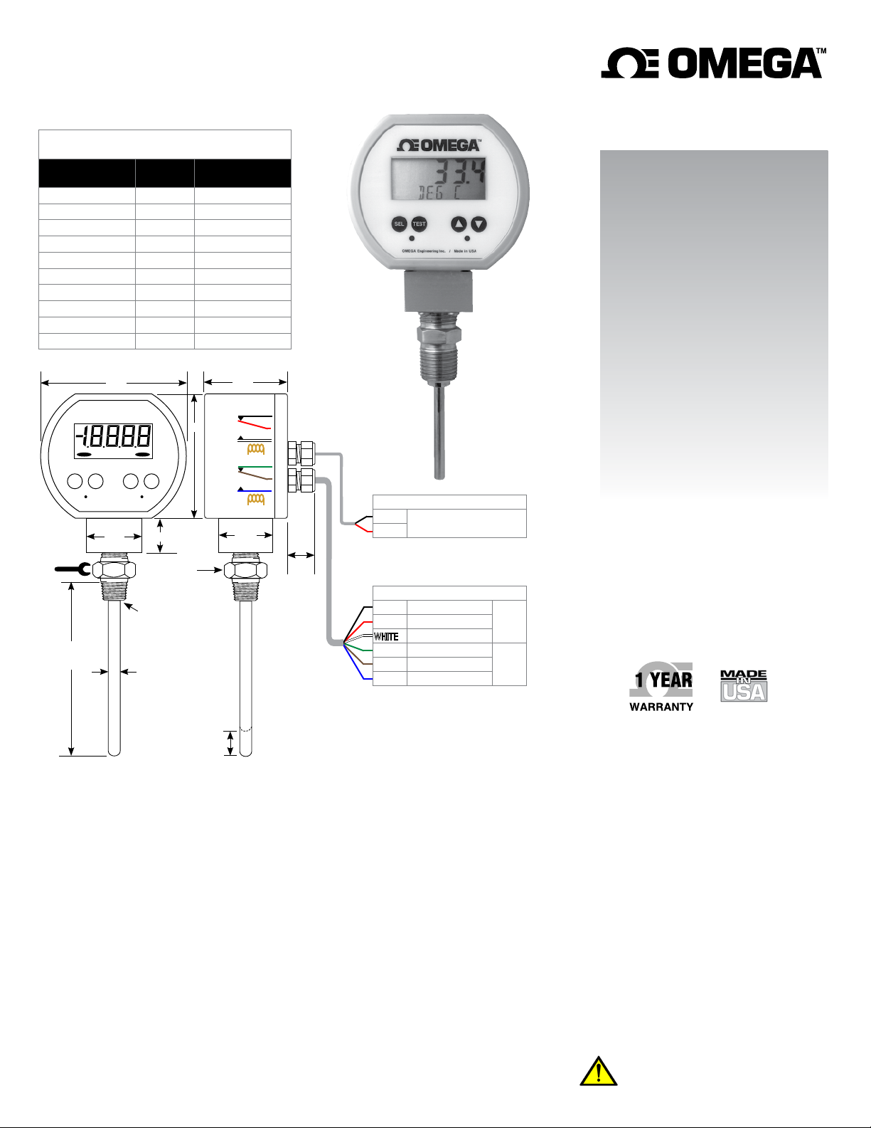
PRTXAL Series RTD Temperature Alarms
2 SPDT Configurable Relays
3.5"
8
1.37"
8
8
PROBE
LENGTH
2.5"
2.5"
4"
4"
6"
6"
9"
9"
12"
12"
s
t
.75"
Hex nipple
1/2" NPT x 1/2" NPT
316 stainless
Continuous
weld on
non-spring
loaded
models
.25" dia.
Spring-loaded models
approx. .25" longer to
compress element in
thermowell.
compression
MODEL
PRTXAL-2
PRTXAL-2-SL
PRTXAL-4
PRTXAL-4-SL
PRTXAL-6
PRTXAL-6-SL
PRTXAL-9
PRTXAL-9-SL
PRTXAL-12
PRTXAL-12-SL
*
Thermowell required for spring-loaded versions
ALARM 1 ALARM 2
XXXXX
8
8
SEL
TEST
Turn at
hex
fitting
only!
Stem
Length
L
Range and Resolution
User selectable °F, °C or K
–58.0°F to 392.0°F
–50.0°C to 200.0°C
220.0K to 475.0K
0.1 degree resolution
Typical Accuracy
Includes linearity error and ±1 LSD
11-point linearization
±0.7°C at –50°C
±0.4°C at 0°C
±0.9°C at 100°C
±1.4°C at 200°C
Sensor
100 Ω RTD element
0.00385 alpha coefficient
IEC-751 Class B: ±0.3°C at 0°C, ±1.1°C at 150°C
10 second time constant
Display
4 digit LCD, 1/2” digit height, alphanumeric lower display for units
4 readings per second nominal display update rate
Alarm Outputs
Dual form C (SPDT) relay contacts
Relay contacts rated 1A/24VDC, 0.5A/115VAC, non-inductive
Bi-color (red/green) LEDs on front panel
Alarm trip update rate approximately 4 times per second
PROBE
TYPE
Fixed
Spring-Loaded
Fixed
Spring-Loaded
Fixed
Spring-Loaded
Fixed
Spring-Loaded
Fixed
Spring-Loaded
NC 1
3.0"
C 1
NO 1
NC 2
C 2
NO 2
.50" max.
*
*
*
*
*
"
2.0
1.25"
Probe length is measured
from top of full threads to
tip of probe.
Length = thermowell
“A” or “element length”
dimension.
2-conductor 22 AWG power cable
BLACK
RED
.75"
BLACK Normally Closed (NC)
GREEN Normally Closed (NC)
BLUE Normally Open (NO)
Alarm Contact Ratings
0.5A/115VAC, 1A/24VDC, non-inductive
Setpoint Functionality
Two independent alarm set points
Setpoint 1 high or low alarm
Setpoint 2 high or low alarm
Setpoint 1 deadband adjustment
Setpoint 2 deadband adjustment
Normal or reverse acting relays
Test Function
Front panel TEST button toggles both SP1 and SP2 alarm status,
independent of temperature input to allow testing of system
operation. Access can be pass code protected.
Out of Range Indication
User configurable upscale or downscale burnout
ALARM1 on display above 392°F or 200°C
ALARM2 on display below –58°F or –50°C
Below approx. –103°F (–75°C) or above approx. 482°F (250°C),
the display will indicate 1.-.-.-.
Controls and Functions
TEST Test alarm function
SEL Select
s Up: increment up for setup, pass code, or calibration
t Down: increment down for setup, pass code, or
calibration
8 to 24 VAC 50/60 Hz or
9 to 32 VDC
6-conductor 22 AWG relay cable
Normally Open (NO)
User’s Guide
Shop online at
omega.com
e-mail: [email protected]
For latest product manuals:
www.omegamanual.info
SPDT 1RED Common (C)
SPDT 2BROWN Common (C)
TM
Calibration
User settable pass code to enter calibration mode
Zero and span temperature calibration
Electrical Connections
3 foot long, 2-conductor 22AWG cable for power
3 foot long, 6-conductor 22AWG cable for relays
Power
8 to 24 VAC 50/60 Hz or 9 to 32 VDC
1.0 watt maximum power consumption
Weight
Thermometer: approx. 14 ounces
Shipping weight: approx. 1 pound
Housing
NEMA 4X ABS/polycarbonate, gasketed rear cover
Connection and Probe Material
1
/2" NPT male hex nipple, 316 stainless steel
316 stainless steel probe sheath
Environmental
Storage: –40 to 203°F (–40 to 95°C) at housing
Operating: –4 to 185°F (–20 to 85°C) at housing
WARNING: This product can expose you to chemicals including
lead, nickel and chromium, which are known to the State of
California to cause cancer or birth defects or other reproductive
harm. For more information go to www.P65Warnings.ca.gov
Page 2
2
PRTXAL Series RTD Process Temperature Alarms
Precautions
Read these instructions before installation. Configuration may be
easier before installation.
Avoid shock hazards! Turn power off before connecting or
disconnecting wiring. All wiring must be performed by a qualified
electrician or instrumentation technician. See diagrams on other
side for wiring examples. Consult factory for assistance.
Install or remove thermometer using a wrench on the hex fitting
only. Do not attempt to turn by forcing the housing.
Do not exceed maximum allowable housing temperature.
The spring-loaded design must be used with a thermowell. The non-
spring-loaded design can be used in non-pressurized applications
or applications with no flow. Due to the hardness of 316 stainless
steel, it is recommended that a thread sealant be used to ensure
leak-free operation.
Normal Operation
The factory default configuration is °F, downscale burnout, Setpoint
1 High Alarm, Setpoint 2 Low Alarm, 1.0 degree alarm deadband,
normal acting relays, no pass code required for configure/test
alarms mode.
To turn the unit on, apply power. If so equipped, the optional display
backlighting will be on. The display backlighting will not be apparent
under bright lighting conditions.
The display segments are tested for approximately 1 second. During
the startup sequence, the alarm relays are de-energized and the
alarm status LEDs are off.
After power-up the RTD temperature and units are displayed along
with the alarm relay states as indicated by the LEDs. The display
and alarm status are updated approximately 4 times per second,
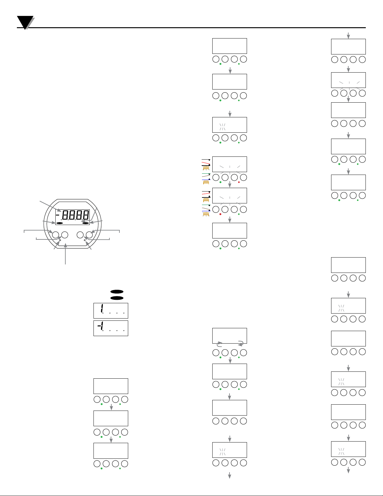
Display and Keypad
Numeric
display
RTD over-
range
Select Test Up Down
ALARM 1
XXXXX
8
8
8
8
8
SEL
TEST
s
ALARM 2
t
Lower alpha-
numeric display
RTD under-
range
*
Alarm 1 status LED
Green = Normal
Red = Alarm
Red blinking LED = unacknowledged alarm
Press Test to acknowledge alarm
Out-of-Range Indications
RTD over-range condition >392.0°F or >200.0°C
RTD under-range condition <–58.0°F or <–50.0°C
If the RTD temperature is outside of the
extrapolated range, a burnout condition will
be assumed.
1. . . . if upscale burnout is selected
–1. . . . if downscale burnout is selected.
Alarm Indications
The relevant bi-color LED will be illuminated green for a normal
condition or red for an alarm condition.
The red LED will blink at a slow rate until the alarm is acknowledged
or the alarm condition clears.
To acknowledge an alarm condition, press and release the TEST
button.
Viewing Alarm Trip Points
The RTD temperature, the value of Trip
Point 1, and the value of Trip Point 2 may be
selected for display as follows.
When the RTD temperature is being
displayed, press and release the SEL
(select) button. The Trip Point 1 value will be
displayed with TRIP1 on the lower display.
When the Trip Point 1 value is being
displayed, press and release the SEL button.
The Trip Point 2 value will be displayed with
TRIP2 on the lower display.
When the Trip Point 2 value is being
displayed, press and release the SEL button.
The RTD temperature will be displayed.
Alarm 2 status LED
Green = Normal
Red = Alarm
ALARM 1
ALARM 2
DEG F
DEG F
200.0
TRIPI
SEL
TEST
s
*
I80.0
TRIP2
SEL
TEST
s
*
I88.0
DEG F
SEL
TEST
s
t
t
t
*
Alarm Test Mode
This mode allows testing of the alarms
regardless of the alarm trip points or the
temperature reading.
From the normal mode with temperature
being displayed, press and hold the TEST
button and then press the SEL button.
Release both buttons when the display
indicates - - - - .
- or If pass code protection is enabled, before
the unit enters the Alarm Test Mode, the
display initially indicates _ _ _ _ with the
left-most underscore blinking, and with
TSTPC on the lower display. Enter the userdefined pass code (3510 factory default) as
described in the Pass Code Entry section.
Note: During pass code entry the LEDs will
turn off and the unit will not respond to
changes in RTD temperature. The alarm
relays will maintain their prior states. The
unit will automatically revert to normal
operation if no buttons are operated for
approximately 15 seconds.
While in the Alarm Test Mode
with no buttons pressed,
the display will indicate the
temperature with DEG C or DEG
F slowly blinking on the lower
display.
While the TEST button is pressed
and held, both LED indicators
and alarm relays will toggle to
their opposite state. The display
will continue to indicate the
temperature.
To exit the Alarm Test Mode,
press and release the SEL
button. The display briefly
indicates - - - - and then returns
to normal operation.
Adjusting Set Points
Go to the User Configuration Mode to set up the alarm parameters
before setting up the alarm setpoints. Whenever the user
configuration mode is entered, even if no changes are made, all
alarm set points will be reset to the factory default maximum and
minimum values.
Alarm 1 factory default: HI alarm, 392.0°F trip point.
Alarm 2 factory default: LO alarm, –58.0°F trip point.
“Set Point” is defined as the temperature that will result in a change
of state only from a normal to an alarm condition.
“Trip Point” is defined as the temperature value that will result in
a change of state of alarm condition, and includes the effect of
deadband when returning from an alarm to
a normal condition.
The instructions illustrate how to change
Trip Point 1. The procedure is the same for
Trip Point 2.
From the normal mode press and release
the SEL button to display Trip Point 1. If
you want to change Trip Point 2, press SEL
again until TRIP2 is displayed.
While TRIP1 is displayed, press and hold the
TEST button and then press the SEL button.
NC 1
C 1
NO 1
NC 2
C 2
NO 2
NC 1
C 1
NO 1
NC 2
C 2
NO 2
200.0
deg f
SEL
TEST
s
1*2
press both
*
- - - -
SEL
TEST
s
release both
*
*
- or -
____
TSTPC
SEL
TEST
s
release both
*
*
i88.7
deg F
SEL
TEST
s
i88.7
deg f
SEL
TEST
s
*
- - - -
DEG F
SEL
TEST
s
exit
*
200.0
TRIPI
TRIP2
or
SEL
TEST
s
*
200.0
tripi
SEL
TEST
s
1*2
press both
*
t
t
t
t
t
t
t
t
- - - -
Release both buttons when the display
indicates - - - - .
If pass code protection is enabled, before
the unit enters the Alarm Test Mode, the
display indicates _ _ _ _ with the left-most
underscore blinking, and with TSTPC on the
lower display.
SEL
TEST
s
release both
*
*
- or -
____
TSTPC
SEL
TEST
s
release both
*
*
t
t
Enter the user-defined pass code (3510
factory default) as described in the Pass
Code Entry section.
Note: During pass code entry the LEDs
will turn off and the unit will not respond
to changes in RTD temperature. The alarm
relays will maintain their prior states. The
unit will automatically revert to normal
operation if no buttons are operated for
approximately 15 seconds.
While in the Set Point 1 Adjust Mode, the
display will indicate Trip Point 1 with TRIP1
blinking at a slow rate on the lower display.
To adjust Set Point 1, press and hold the
TEST button and the display will indicate
SP1 on the lower display. If the alarm is not
tripped the display will change by an amount
equal to the deadband value.
While holding the TEST button operate the
s and t buttons to adjust Set Point 1 to the
desired value. The Set Point 1 value is stored
when the TEST button is released.
Note that the unit will not respond to
changes in temperature, LEDs are turned off,
and the alarm relays will maintain their prior
states while the TEST button is held.
To change Trip Point 2 press SEL until TRIP
2 is shown. The procedure is the same as
Trip Point 1.
To exit, press the SEL button until the display
indicates - - - -. The unit then returns to
normal operation.
Pass Code Entry
Pass codes are used to prevent unauthorized changes to settings.
Up to three different pass codes can be used to allow access to the
configuration, alarm settings and output test, or calibration.
During pass code entry the LEDs will turn off and the unit will not
respond to temperature changes. The alarm relays will maintain
their prior states. The unit will automatically revert to normal
operation if no buttons are pressed for 15 seconds.
Configuration Pass Code
From the normal operating mode press and
hold the TEST and the s buttons. Then
press the SEL button. Release all buttons
when the display indicates CFG.
The display initially indicates _ _ _ _ with
the first underscore blinking, and with
CFGPC on the lower display.
Enter the user-defined pass code as
described on the next page.
Calibration Pass Code
Press and hold the TEST and the t buttons.
Then press the SEL button. Release all
buttons when the display indicates CAL.
The display initially indicates _ _ _ _ with
the first underscore blinking, and CALPC on
the lower display.
Enter the user-defined pass code as
described on the next page.
Test and Set Point Adjust Pass Code
The optional for pass code protected alarm
testing or set point changes is set in CFG
mode. It is not used in the factory default
configuration.
Press and hold the TEST button. Then press
the SEL button. Release all buttons when the
display indicates - - - - .
If TSTPC pass code is enabled, the display
indicates _ _ _ _ with the first underscore
blinking, and TSTPC on the lower display.
Enter the user-defined pass code as
described on the next page.
35 i0
TSTPC
SEL
TEST
s
*
200.0
TRIPI
SEL
TEST
s
205.0
SP I
SEL
TEST
s
hold
*
250.0
Trip2
SEL
TEST
s
*
- - - -
Trip2
SEL
TEST
s
exit
*
cf6
tpv27
SEL
TEST
s
2
1
*
*
then
together
____
cfgpc
SEL
TEST
s
- or -
CAL
tpv27
SEL
TEST
s
1*2
*
togetherthen
____
calpc
SEL
TEST
s
- or -
- - - -
SEL
TEST
s
1*2
*
then
____
tstpc
SEL
TEST
s
t
t
t
or
*
t
t
t
1
*
t
t
1
t
t
t
*
*
Page 3
PRTXAL Series RTD Temperature Alarms
3
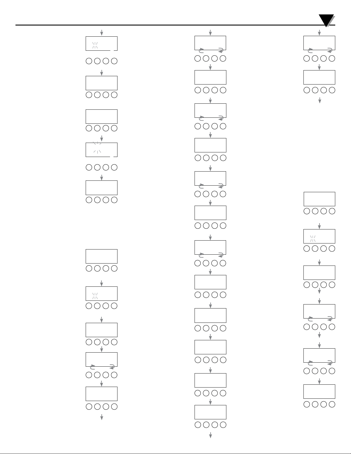
User-Defined Pass Code Entry
Enter the user-defined pass code (3510
factory default).
Use the s and t buttons to increase or
decrease the numerical value.
Press and release the SEL button to index to
the next position.
Once the 4-digit the user-defined pass code
has been entered, press and release the
SEL button to proceed to the specific mode
of operation.
Note: If an incorrect pass code was entered,
the unit will to exit to the normal operating
mode.
Pass Code Modification
To modify any of the default factory pass
codes, enter pass code 1220 using the same
procedure as described above.
Once the 1220 pass code has been entered,
press and release the SEL button to proceed.
If an incorrect pass code was entered, the
unit will to exit to the normal operating
mode.
The display will then indicate the existing
pass code with CFGPC, CALPC, or TSTPC
on the lower display, depending on the key
combination used.
Operate the s or t button to select the first
character of the new pass code. Press and
release the SEL button to proceed to the next
character. Repeat until the entire pass code
is complete. Write down the new pass code
in a secure place.
To exit the Pass Code Modification mode,
press and hold the SEL button. Release the
button when the display indicates - - - - to restart the unit in the
normal mode.
User Configuration Mode
Whenever the user configuration mode is entered, even if no
changes are made, all alarm set points will be reset to the factory
default maximum and minimum values.
From the Normal Mode with RTD
temperature being displayed, press and hold
the TEST and the s buttons. Then press the
SEL button. Release all buttons when the
display indicates CFG.
Enter the user-defined pass code (3510
factory default) as described in the Pass
Code Entry section.
____
cfgpc
calpc
TSTpc
SEL
TEST
s
next #
*
35 i0
SEL
TEST
s
i220
SEL
TEST
s
hold
*
35 i0
cfgpc
calpc
cfgpc
SEL
TEST
s
next #
*
- - - -
SEL
TEST
s
save and exit
*
cf6
tpv27
SEL
TEST
s
2
1
*
*
then
together
____
cfgpc
SEL
TEST
s
move
*
to next
1
or
or
or
*
or
*
or
or
or
*
*
or
*
t
t
t
t
t
t
t
35 i0
cfgpc
SEL
TEST
s
t
Temperature Scale Selection
The upper display will be blank, and the
lower section will display either DEG C or
DEG F.
To change from degrees Celsius to
Fahrenheit, press and release the s button.
The lower display will change to DEG F.
To change from degrees Fahrenheit to
Celsius, press and release the t button.
The lower display will change to DEG C.
Press and release the SEL button to move on
to the next parameter.
def f
deg c
SEL
TEST
deg f
SEL
TEST
press to save
*
s
t
or
*
s
t
Upscale/Downscale Burnout Action
The upper display will be blank, and the
lower section will display either DN BO or
UP BO.
To change from Downscale Burnout to
Upscale Burnout, press and release the s
button. The lower display will change to UP
BO.
*
To change from upscale burnout to
downscale burnout, press and release the
t button. The lower display will change to
DN BO.
Press and release the SEL button to move on
to the next parameter.
Set Point 1 LO or HI
The upper display will be blank, and the
lower section will display either SP1LO or
SP1HI.
To configure Setpoint 1 as a High Alarm,
press and release the s button. The lower
*
section of the display will indicate SP1HI.
To configure Setpoint 1 as a Low Alarm,
press and release the t button. The lower
section of the display will indicate SP1LO.
Press and release the SEL button to move on
to the next parameter.
Set Point 2 LO or HI
*
The upper display section will be blank, and
the lower section will display either SP2LO
or SP2HI.
To configure Setpoint 2 as a High Alarm,
press and release the s button. The lower
section of the display will indicate SP2HI.
To configure Setpoint 2 as a Low Alarm,
press and release the t button. The lower
section of the display will indicate SP2LO.
Press and release the SEL button to move on
to the next parameter.
Normal/Reverse Alarm Action
The upper display section will be blank, and
the lower section will display either NOR
or REV.
To configure the relays for reverse action,
press and release the s button. The lower
section of the display will indicate REV.
To configure the relays for normal action,
press and release the t button. The lower
section of the display will indicate NOR.
Press and release the SEL button to move on
to the next parameter.
*
Set Point 1 Deadband
The upper display will indicate the Setpoint 1
deadband in °C or °F, and the lower section
will display SP1DB.
Use the s and t buttons to set the desired
Setpoint 1 deadband value.
Press and release the SEL button to move on
to the next parameter.
Set Point 2 Deadband
*
The upper display will indicate the Setpoint 2
deadband in °C or °F, and the lower section
will display SP2DB.
Use the s and t buttons to set the desired
Setpoint 2 deadband value.
Press and release the SEL button to move on
to the next parameter.
up bo
dn bo
SEL
TEST
up bo
SEL
TEST
press to save
*
spihi
spilo
SEL
TEST
spihi
SEL
TEST
press to save
*
sp2hi
sp2lo
SEL
TEST
sp2lo
SEL
TEST
press to save
*
nor
rev
SEL
TEST
rev
SEL
TEST
press to save
*
spidb
SEL
TEST
spidb
SEL
TEST
press to save
*
sp2db
SEL
TEST
sp2db
SEL
TEST
press to save
*
s
or
*
s
s
or
*
s
s
or
*
s
s
or
*
s
0.5
s
or
*
i.o
s
0.5
s
or
*
i,0
s
Test Mode and Set Point Security
The upper display will be blank, and the
lower section will display either TSTPC or
NOTPC.
To enable Test and Set Point Adjust Mode
pass code protection, press and release the
t
s button. The lower section of the display
*
will indicate TSTPC.
To disable Test and Set Point Adjust Mode
pass code protection, press and release the
t button. The lower section of the display
will indicate NOTPC.
t
Save Settings and Exit
Press and release the SEL button to save
the configuration parameters and restart the
unit. Note: The configuration parameters will
not be saved if the procedure is interrupted before completion.
The unit proceeds through a restart sequence during which all active
display segments are turned on for approximately 1 second. During
t
the restart sequence, the alarm relays are de-energized, the alarm
*
status LEDs are off.
Calibration
Temperature calibration is performed at two points: ice point and
t
at a temperature above ice point. For general service, the full scale
temperature is normally used for the second point. However, if a
particular temperature is of critical interest, it may be used instead
for greatest accuracy at that point. When the applied temperature
is below approximately 12 °C (or 54 °F), the unit will automatically
select the ice-point calibration mode.
Entering Calibration Mode
From the normal mode with RTD
t
temperature being displayed, press and hold
*
the TEST and the t buttons. Then press the
SEL button. Release all buttons when the
display indicates CAL.
Enter the user-defined pass code (3510
factory default) as described in the Pass
t
Code Entry section.
Upon successful pass code entry, the upper
segments of the display will indicate the RTD
probe temperature. The lower segments of
the display will alternate as indicated below.
Note: To store the calibration parameters
and exit calibration mode at any time, press
and hold the SEL button until the display
t
indicates - - - - .
*
t
Ice-Point Calibration
Apply 0.0°C or 32.0°F to the RTD. The lower
display segments will alternate between ICE
and DEG C or DEG F.
Use the s and t buttons to adjust the
upper display segments to indicate 0.0°C
t
or 32.0°F.
SEL
SEL
SEL
2
then
____
SEL
SEL
sensor at ice point
SEL
*
Span Calibration
Apply full-scale temperature to the RTD.
The lower display segments will alternate
between CAL and DEG C or DEG F.
Use the s and t buttons to adjust the
t
upper display segments to indicate the
applied temperature value.
Exit and Save
To store the calibration parameters and exit
t
calibration mode, press and continue to hold
*
the SEL button until the display indicates
- - - - .
t
sensor at span point
250.0
SEL
SEL
tstpc
notpc
TEST
s
t
or
*
notpc
TEST
s
press to save & exit
*
unit restarts
t
cal
tpv27
TEST
s
t
1
*
*
together
calpc
TEST
s
or
*
t
move
*
to next
35 i0
calpc
TEST
s
t
32.0
ice
deg f
TEST
s
t
or
*
cal
deg f
TEST
s
t
or
*
- - - -
TEST
s
hold to save and exit
*
t
*
1
*
*
*
*
Page 4

WARRANTY/DISCLAIMER
OMEGA ENGINEERING, INC. warrants this unit to be free of defects in materials and workmanship for a
period of 13 months from date of purchase. OMEGA’s WARRANTY adds an additional one (1) month
grace period to the normal one (1) year product warranty to cover handling and shipping time. This
ensures that OMEGA’s customers receive maximum coverage on each product.
If the unit malfunctions, it must be returned to the factory for evaluation. OMEGA’s Customer Service
Department will issue an Authorized Return (AR) number immediately upon phone or written request.
Upon examination by OMEGA, if the unit is found to be defective, it will be repaired or replaced at no
charge. OMEGA’s WARRANTY does not apply to defects resulting from any action of the purchaser,
including but not limited to mishandling, improper interfacing, operation outside of design limits,
improper repair, or unauthorized modification. This WARRANTY is VOID if the unit shows evidence of
having been tampered with or shows evidence of having been damaged as a result of excessive corrosion;
or current, heat, moisture or vibration; improper specification; misapplication; misuse or other operating
conditions outside of OMEGA’s control. Components in which wear is not warranted, include but are not
limited to contact points, fuses, and triacs.
OMEGA is pleased to offer suggestions on the use of its various products. However,
OMEGA neither assumes responsibility for any omissions or errors nor assumes liability for
any damages that result from the use of its products in accordance with information provided
by OMEGA, either verbal or written. OMEGA warrants only that the parts manufactured by the
company will be as specified and free of defects. OMEGA MAKES NO OTHER WARRANTIES OR
REPRESENTATIONS OF ANY KIND WHATSOEVER, EXPRESSED OR IMPLIED, EXCEPT THAT OF
TITLE, AND ALL IMPLIED WARRANTIES INCLUDING ANY WARRANTY OF MERCHANTABILITY
AND FITNESS FOR A PARTICULAR PURPOSE ARE HEREBY DISCLAIMED. LIMITATION OF
LIABILITY: The remedies of purchaser set forth herein are exclusive, and the total liability of
OMEGA with respect to this order, whether based on contract, warranty, negligence,
indemnification, strict liability or otherwise, shall not exceed the purchase price of the
component upon which liability is based. In no event shall OMEGA be liable for
consequential, incidental or special damages.
CONDITIONS: Equipment sold by OMEGA is not intended to be used, nor shall it be used: (1) as a “Basic
Component” under 10 CFR 21 (NRC), used in or with any nuclear installation or activity; or (2) in medical
applications or used on humans. Should any Product(s) be used in or with any nuclear installation or
activity, medical application, used on humans, or misused in any way, OMEGA assumes no responsibility
as set forth in our basic WARRANTY/DISCLAIMER language, and, additionally, purchaser will indemnify
OMEGA and hold OMEGA harmless from any liability or damage whatsoever arising out of the use of the
Product(s) in such a manner.
RETURN REQUESTS/INQUIRIES
Direct all warranty and repair requests/inquiries to the OMEGA Customer Service Department.
BEFORE RETURNING ANY PRODUCT(S) TO OMEGA, PURCHASER MUST OBTAIN AN AUTHORIZED
RETURN (AR) NUMBER FROM OMEGA’S CUSTOMER SERVICE DEPARTMENT (IN ORDER TO AVOID
PROCESSING DELAYS). The assigned AR number should then be marked on the outside of the return
package and on any correspondence.
The purchaser is responsible for shipping charges, freight, insurance and proper packaging to prevent
breakage in transit.
FOR WARRANTY RETURNS, please have the
following information available BEFORE contacting
OMEGA:
1. Purchase Order number under which the product
was PURCHASED,
2. Model and serial number of the product under
warranty, and
3. Repair instructions and/or specific problems
relative to the product.
OMEGA’s policy is to make running changes, not model changes, whenever an improvement is possible. This affords
our customers the latest in technology and engineering.
OMEGA is a registered trademark of OMEGA ENGINEERING, INC.
© Copyright 2017 OMEGA ENGINEERING, INC. All rights reserved. This document may not be copied, photocopied,
reproduced, translated, or reduced to any electronic medium or machine-readable form, in whole or in part, without the
prior written consent of OMEGA ENGINEERING, INC.
FOR NON-WARRANTY REPAIRS,
OMEGA for current repair charges. Have
the following information available BEFORE
contacting OMEGA:
1. Purchase Order number to cover the COST
of the repair,
2. Model and serial number of the product, and
3. Repair instructions and/or specific problems
relative to the product.
consult
 Loading...