

Page 1
PowerDAQ Programmer Manual
PowerDAQ PD2-MF(S), AO and DIO PCI DAQ boards
Windows 9x/NT/2000, Linux, RTLinux, RTAI and QNX
High-Performance oards for PCI Bus Computers
March 2001 Edition
© Copyright 1998-2001 Omega Engineering, Inc. All rights reserved
Page 2

Table of Contents
All rights reserved. No part of this publication may be reproduced,
stored in a retrieval system, or transmitted, in any form by any means,
electronic, mechanical, by photocopying, recording, or otherwise
without prior written permission.
First Edition
March 2001 Printing
Information furnished in this manual is believed to be accurate and
reliable. However, no responsibility is assumed for its use, or for any
infringements of patents or other rights of third parties that may result
from its use.
Contacting Omega Engineering
✉
Address:
OMEGA Engineering, Inc.
One Omega Drive
Stamford, Connecticut 06907-0047
U.S.A.
! Support:
Telephone: 1-800-622-2378
Fax: 1-800-848-4271
"Internet Access:
Support [email protected]
Web site http://www.omega.com
FTP site ftp://ftp.omega.com
Page 3

Table of Contents
Table of Contents
PowerDAQ API Overview......................................................3
General considerations and API structure ............................................ 3
Variables naming convention................................................................ 3
Error values............................................................................................ 3
Writing user applications for Microsoft Windows 9x, NT and 2000 .. 3
PowerDAQ Libraries........................................................................... 4
PowerDAQ Include Files .................................................................... 4
Writing user applications for Linux and Realtime Linux ...................... 5
Writing user applications for QNX ........................................................7
General Functions....................................................................9
Start talking to the board ..................................................................... 9
Adapter capabilities information functions .........................................16
Buffer Management Functions........................................................... 24
On-board EEPROM access and calibration functions ......................31
Event and interrupt control functions............................................. 34
Analog Input Subsystem Functions................................... 51
Analog Input immediate mode functions............................................ 51
Clocking ........................................................................................... 56
Analog Input buffered mode functions ..............................................70
Analog Output Subsystem Functions ...............................79
Analog Output immediate mode functions (PD2-MF/S boards only)79
Analog Output asynchronous mode functions (PD2-MFx board)..... 88
Analog Output immediate mode functions (PD2-AO board)............ 94
Analog Output asynchronous mode functions (PD2-AO board)....... 98
Digital I/O Subsystem Functions .....................................106
Digital Input/Output immediate mode functions (PD2-MFx board) 106
Digital Input/Output immediate mode functions (PD2-DIO board) .112
Digital Input asynchronous mode functions (PD2-DIO board) ..........121
Digital Output asynchronous mode functions (PD2-DIO board)...... 127
Counter-Timer Subsystem Functions..............................136
General UCT access functions ........................................................... 136
Counter data stream function (PD2-DIO board only) ......................146
i
Page 4

Page 5
1
PowerDAQ API Overview
Page 6

Page 7

Chapter 1: PowerDAQ API overview
PowerDAQ API Overview
General considerations and API structure
Variables naming convention
Error values
PowerDAQ Win32 and Linux APIs functions return error codes on failure.
Win32: if function fails it returns FALSE (0) as a return value and error
code (from WinError.h) in pdwError. See WinError.h for details. If you have
MS SDK installed you could find WinError.h in C:\MSSDK\include\. If you
have Visual Studio installed you can find WinError.h in C:\Program
Files\Microsoft Visual Studio\VC98\Include\.
Linux: if function succeeds it returns a zero (sometimes positive) value. If
function fails it returns negative value. You can find the meaning of these
values by looking into /linux/include/errno.h.
Writing user applications for Microsoft
Windows 9x, NT and 2000
The PowerDAQ SDK CD installs the driver and DLLs for Windows 9x, NT
and 2000 OSes. These files are crucial to operate any PowerDAQ board:
The following driver/DLL files are installed:
Windows 9x operating System:
Location: \windows\system directory
pwrdaq95.vxd device driver
PwrDAQ32.dll 32-bit DLL
PwrDAQ16.dll 16-bit DLL
Windows NT operating system:
Location: \winnt\system32\drivers
pwrdaq.sys device driver
3
Page 8

Chapter 1: PowerDAQ API overview
Location: \winnt\system32
PwrDAQ32.dll 32-bit DLL
Windows 2000 operating system:
Location: \winnt\system32\drivers
pwrdaq2k.sys device driver
Location: \winnt\system32
PwrDAQ32.dll 32-bit DLL
PowerDAQ Libraries
PowerDAQ SDK contains libraries for all major software development tools.
They are located in the /lib directory. The following libraries are supplied
for Win32/Win16 platforms:
pwrdaq32.lib - MSVC/MSVS v.5.x, 6.x
pd32bb.lib - Borland C++ Builder v.3.0 - 5.0
pd16bb.lib - 16-bit Borland compilers
pd16bc45.lib - 16-bit Borland C++ 4.5x
pwrdaq16.lib - 16-bit MSVC 1.5x
PowerDAQ Include Files
/include
pdfw_def.h - firmware constant definition file for C/C++
pdfw_def.pas - firmware constant definition file for
Borland Delphi
pdfw_def.bas - firmware constant definition file for
Visual Basic
pwrdaq.h - driver constants and definitions file for
C/C++
pwrdaq.pas - driver constants and definitions file for
Borland Delphi
pwrdaq.bas - driver constants and definitions file for
Visual Basic
pwrdaq32.h - API function prototypes and structures file
for C
pwrdaq32.hpp - API function prototypes and structures file
for C++
pwrdaq32.pas - API function prototypes and structures file
for Borland Delphi
pwrdaq32.bas - API function prototypes and structures file
for Visual Basic
pd_hcaps.h - boards capabilities definition file for
C/C++
pd_hcaps.pas - boards capabilities definition
file for Borland Delphi
pd_hcaps.bas - boards capabilities definition file for
Visual Basic
4
Page 9

Chapter 1: PowerDAQ API overview
vbdll.bas - auxiliary functions to access PowerDAQ
buffer from within VB
Aliases.bas - auxiliary functions to access PowerDAQ
structures from within VB
PdApi.bas - module used in SimpleTest VB example
/include/vb3
pwrdaq16.bas - API function prototypes and
structures file for Visual Basic v.3.0
pdfw_def.bas - firmware constant definition file for Visual
Basic v.3.0
pd_hcaps.bas - boards capabilities definition file for
Visual Basic v.3.0
daqdefs.bas - event word definition for Visual Basic v.3.0
/include/16-bit
pwrdaq16.h - API function prototypes and structures file
for 16-bit C/C++
pwrdaq.h - driver constants and definitions
file for 16-bit C/C++
pdd_vb3.h - auxiliary functions to access PowerDAQ
structures from within VB v.3.0
pd_hcaps.h - boards capabilities definition
file for 16-bit C/C++
Writing user applications for Linux and
Realtime Linux
The same driver – pwrdaq.o can be used for both realtime and nonrealtime applications.
There are five ways to access the driver:
1. From the user space link your program with powerdaq32.lib
2. From the user space link your program dynamically with the library
(install powerdaq32.o as a shared library)
3. From the user space use simple “read” and “write” commands (you
can access only basic read/write for analog and digital subsystems this
way).
4. Link your realtime module with powerdaq32.o. ( _PD_RTL symbol
should be defined). Every function call to the PowerDAQ API will be
translated into posixio() style calls to the ioctl() entry point of the
driver.
5. Call exported functions of the pwrdaq.o module directly. It’s the
fastest way to call the driver functions however no ownership and race
condition checking occurs.
Please refer to README file supplied with the PowerDAQ for Linux tarball.
5
Page 10
Chapter 1: PowerDAQ API overview
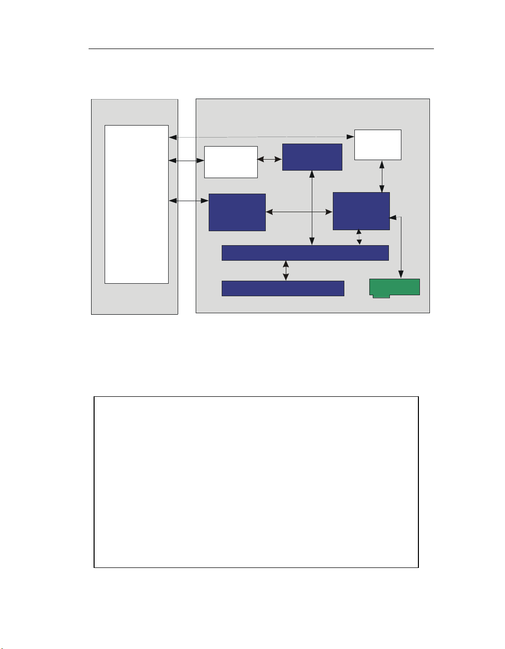
Typical Realtime Linux spplication architecture is presented on the following
picture:
User Space
Space
User
Application
(Soft ealtime)
Libraries
GUI
Database
Networking
FIFOs
Linux
Kernel
Realtime Kernel (VM layer)
Realtime
+
+
+
+
...
Kernel Space
Hard
Realime
PowerDAQ
driver
Shared
Buffer
Interrupt control hardware
re
PowerDAQ
It includes two parts: realtime task that serves realtime processing and a
user application part. Realtime tasks communicate with the user application
via Realtime FIFOs and shared buffers.
Following breakdown structure outlines Realtime Linux application design:
Functions to Place in Non-Realtime Section
• Boot OS/load modules
• Allocate memory
• Communication with user (User Interface)
• Use of OS services (database, networking, file system)
• Communication with realtime task through realtime FIFOs
• Hardware initialization and reset
Functions to Place in Realtime Section
• Process interrupts
• Get/put data from/to device
• Calculate response (FPU is available)
• Put/get data into/from realtime FIFOs
• Schedule other realtime tasks (periodic and non-periodic)
6
Page 11
Chapter 1: PowerDAQ API overview
Writing user applications for QNX
PowerDAQ for QNX support includes the following files:
pd2_dao.c - function library for PD2-DIO and PD2-AO
boards
pdfw_def.h - firmware constant definition
pdfw_if.h - driver interface definition
pdfw_lib.lib - library to link with application
pdfw_lib.o - function library object file
pdfwmain_i.h - firmware hex file (downloads automatically)
pd-int.h - PowerDAQ QNX driver definitions (pd_board[]
structure and substructures)
powerdaq.h - PowerDAQ QNX driver definitions to include
into the library and applications
win2qnx.h - Windows DDK types conversion
into QNX types
pd.c - startup code example
pd_ain.c - software-clocked analog input example
pd_aio.c - hardware-paced analog input/output control
loop
Implemting a QNX driver is different than Windows or Linux drivers. QNX
allows applicationa with root privileges to access the PCI bus addresses and
resources (including interrupts) directly. This is why the driver does not
contain read()/write()/ioctl() routines.
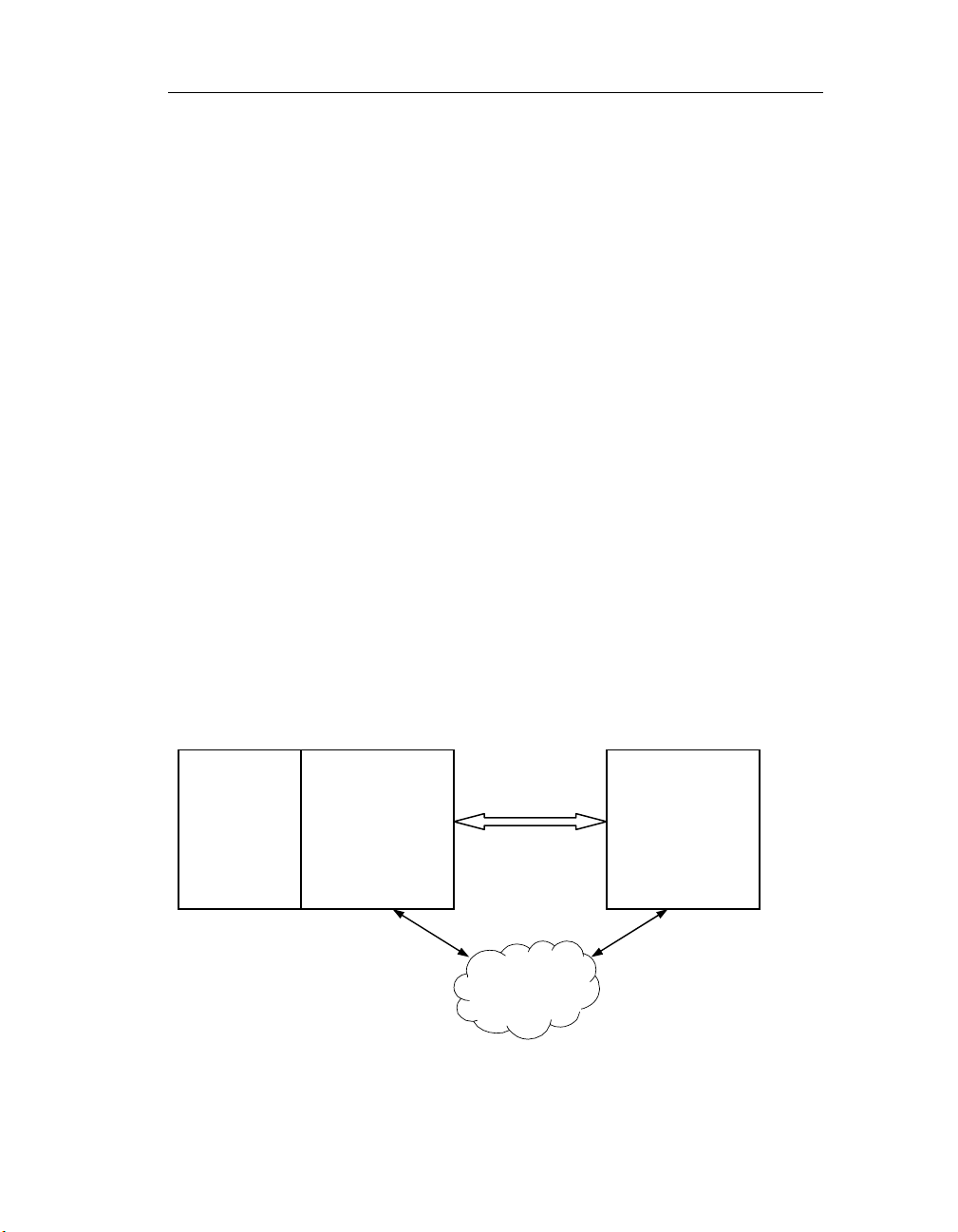
The PowerDAQ for QNX driver is implemented as a library to link with user
back-end applications (server).
PowerDAQ
library
talks to
hardware
7
Back-end
process
(server)
Front-end
process
(client)
Network
Page 12
2
General Functions
8
Page 13
Chapter 2: General Function
General Functions
Start talking to the board
This group includes functions to open driver, adapter, get number of
adapters installed, acquire/release subsystem and close driver and adapter.
Win32 Linux
Function
name
Function Opens driver and connects user application to it.
Returns TRUE (1) if success, FALSE (0) is failure
Syntax:
Win32 API BOOL PdDriverOpen(PHANDLE phDriver, PDWORD
Win16 API use _PdAdapterOpen() instead (see below)
Linux API use _PdAcquireSubsystem() instead (see below)
RTLinux API driver is always open upon RT module starts (see
QNX API use pd_find_devices() (see below)
Input parameters: None
Output parameters:
PHANDLE phDriver – handle to pwrdaq.sys driver
PDWORD pError – error code on failure
PDWORD pNumAdapters – number of PowerDAQ adapters found in your
system
Function is to be called first in the application.
Win32 Win16
Function name Close Driver
Function Closes driver and disconnects user application from it.
Returns TRUE (1) if success, FALSE (0) is failure
Syntax:
Win32 API BOOL PdDriverClose(HANDLE hDriver, PDWORD
Win16 API use _PdAdapterClose() instead (see below)
Linux API use _PdAcquireSubsystem() instead (see below)
RTLinux API driver closes automatically on rmmod
QNX API use pd_clean_devices (see below)
Open Driver
pError, PDWORD pNumAdapters);
below)
pError);
9
Page 14
Chapter 2: General Function
Input parameters:
HANDLE hDriver – handle received upon PdDriverOpen() successful call
Output parameters:
PDWORD pError – error code on failure
This is the last function is to be called in the application.
Win32 Win16
Function name Open Adapter
Function Initializes the specified PowerDAQ board and returns a
handle to it.
Returns TRUE (1) if success, FALSE (0) is failure
Syntax:
Win32 API BOOL _PdAdapterOpen(DWORD dwAdapter, PDWORD
pError, PHANDLE phAdapter);
Win16 API BOOL _PdAdapterOpen(HWND hWnd, DWORD
dwAdapter, LPDWORD lpError, LPHANDLE lphAdapter);
Linux API use _PdAcquireSubsystem() instead (see below)
RTLinux API adapter is always open upon RT module starts (see
below)
QNX API use pd_find_devices() (see below)
Win32:
Input parameters:
DWORD dwAdapter – number of adapter to open [0..31]
Output parameters:
PHANDLE phAdapter – handle to adapter
PDWORD pError – error code on failure
Win16:
Input parameters:
HWND hWnd – handle to the main window of 16-bit application that
process messages
DWORD dwAdapter – number of adapter to open [0..31]
Output parameters:
LPHANDLE lphAdapter – handle to adapter
LPDWORD lpError – error code on failure
Call this function after driver is open but before acquiring any subsystem.
10
Page 15
Chapter 2: General Function
Win32 Win16
Function name Close Adapter
Function
Returns TRUE (1) if success, FALSE (0) is failure
Syntax:
Win32 API BOOL _PdAdapterClose(HANDLE hAdapter, PDWORD
Win16 API BOOL _PdAdapterClose(HANDLE hAdapter, PDWORD
Linux API use _PdAcquireSubsystem() instead (see below)
RTLinux API driver closes automatically on rmmod
QNX API use pd_clean_devices() (see below)
Input parameters:
HANDLE hAdapter – handle to adapter received from _PdAdapterOpen
Output parameters:
PDWORD pError – error code on failure
Win32 Win16 Linux
Function name Get Driver Version
Function Returns SDK number
Returns TRUE (1) if success, FALSE (0) is failure
Syntax:
Win32 API BOOL PdGetVersion(HANDLE hDriver, PDWORD pError,
Win16 API BOOL PdGetVersion(LPDWORD lpError,
Linux API int PdGetVersion(PPWRDAQ_VERSION pVersion)
RTLinux API access pd_board structure directly
QNX API access pd_board structure directly
Win32:
Input parameters:
HANDLE hDriver – number of adapter to open [0..31]
Output parameters:
PPWRDAQ_VERSION pVersion – version information structure
PDWORD pError – error code on failure
Win16:
Output parameters:
LPPWRDAQ_VERSION lpVersion – version information structure
LPDWORD lpError – error code on failure
Deinitializes the specified PowerDAQ board.
pError);
pError);
PPWRDAQ_VERSION pVersion);
LPPWRDAQ_VERSION lpVersion);
11
Page 16
Chapter 2: General Function
PWRDAQ_VERSION (for Win32 API defined in pwrdaq32.h):
//
// Driver version and timestamp, along with some system facts
//
typedef struct _PWRDAQ_VERSION
{
DWORD SystemSize;
BOOL NtServerSystem;
ULONG NumberProcessors;
DWORD MajorVersion;
DWORD MinorVersion;
char BuildType;
char BuildTimeStamp[40];
} PWRDAQ_VERSION, * PPWRDAQ_VERSION;
Win32 Win16 Linux
Function name Get PCI Configuration
Function Returns data from board’s PCI configuration space
Returns TRUE (1) if success, FALSE (0) is failure
Syntax:
Win32 API BOOL PdGetPciConfiguration(HANDLE hAdapter,
PDWORD pError, PPWRDAQ_PCI_CONFIG pPciConfig);
Win16 API BOOL PdGetPciConfiguration(HANDLE hAdapter,
LPDWORD lpError, LPPWRDAQ_PCI_CONFIG
lpPciConfig);
Linux API int PdGetPciConfiguration(int handle,
PPWRDAQ_PCI_CONFIG pPciConfig)
RTLinux API access pd_board structure directly
QNX API access pd_board structure directly
Win32/Win16:
Input parameters:
HANDLE hAdapter – handle to adapter
Output parameters:
PPWRDAQ_PCI_CONGIG – structure holds PCI configuration space
information
PDWORD pError – error code on failure
Linux
Input parameters:
int handle – subsystem handle (open BoardLevel subsystem)
Output parameters:
12
Page 17
Chapter 2: General Function
PPWRDAQ_PCI_CONGIG – structure holds PCI configuration space
information
Function returns 0 on success or negative error code
Win16 Linux
Function name Get Number of Adapters
Function Returns number of adapters installed in system
Returns TRUE (1) if success, FALSE (0) is failure
Syntax:
Win32 API use PdDriverOpen() to get number of adapters
installed
Win16 API BOOL PdGetNumberOfAdapters(LPDWORD lpError,
LPDWORD lpNumAdapters);
Linux API int PdGetNumberAdapters(void);
RTLinux API use extern int num_pd_boards
QNX API use int pd_find_devices()
Win16:
Input parameters: None
Output parameters:
PDWORD pError – error code on failure
PDWORD lpNumAdapters – number of adapters installed
Linux:
Input parameters: None
Returns: number of adapters installed, 0 if no adapters were found,
negative on error
13
Page 18
Chapter 2: General Function
Win32 Win16 Linux
Function name Acquire Subsystem
Function Get/Release subsystem to/from use
Returns TRUE (1) if success, FALSE (0) is failure
Syntax:
Win32 API BOOL PdAdapterAcquireSubsystem(HANDLE hAdapter,
DWORD *pError, DWORD dwSubsystem, DWORD
dwAcquire);
Win16 API BOOL PdAdapterAcquireSubsystem(HANDLE hAdapter,
LPDWORD lpError, DWORD dwSubsystem, DWORD
dwAcquire);
Linux API int PdAcquireSubsystem(int board, int dwSubsystem,
int Action);
RTLinux API N/A
QNX API N/A
Win32/Win16:
Input parameters:
HANDLE hAdapter – handle to open adapter
DWORD dwSubsystem – subsystem to acquire.
DWORD dwAcuqire – 1 to acquire subsystem, 0 to release it.
Output parameters:
PDWORD pError – error code on failure
Linux:
Input parameters:
int board – board number [0..3]. Call PdGetNumberAdapters() for number
of PowerDAQ boards installed
int dwSubsystem – subsystem to acquire
int Action – 1 to acquire subsystem, 0 to release it
Returns: 0 on success, negative error number on failure
dwSubsystem
_PD_SUBSYSTEM):
{BoardLevel, AnalogIn, AnalogOut, DigitalIn, DigitalOut, CounterTimer,
CalDiag}
can be one of the follows (as defined in typedef enum
14
Page 19
Chapter 2: General Function
QNX
Function name Get boards in use
Function Find and get installed board(s) in use
Returns Number of boards found, negative on error
Syntax:
QNX API int pd_find_devices()
Call this function first in your application.
It perfoms the following:
finds PowerDAQ adapters on the PCI bus
map PCI memory
fill pd_board structure with information about addresses, interrupt line,
etc.
download firmware
download calibration values
QNX driver doesn’t have special functions to access pd_board structure. It’s
assumed that user application accesses it directly. Please refer to pd-int.h
for pd_board structure.
The most important fields are the follows:
typedef struct
{
struct pci_dev *dev; // pointer to PCI device structure
void *address; // effective address of
// board’s memory region
u32 size; // size of the region
int irq; // interrlupt line
[...]
u16 caps_idx; // board type index in pd_hcaps.h
[...]
PD_EEPROM Eeprom; // working copy of on-board EEPROM
PD_PCI_CONFIG PCI_Config; // working copy of board’s
// PCI config space
[...]
} pd_board_t;
Note: pd_board[0] contains information about the first PowerDAQ board
found. The library supports a maximum of 4 boards. If you need to use
more boards in one system you need to increase the value of
PD_MAX_BOARDS (defined in pd-int.h).
15
Page 20
Chapter 2: General Function
QNX
Function name Get boards in use
Function Find and get installed board(s) in use
Returns 0 on success, negative on error
Syntax:
QNX API int pd_clean_devices()
Call this function last in your application.
It shuts down all the boards.
Adapter capabilities information functions
Adapter capabilities functions provide information about adapters installed
and parameters of their subsystems.
Win32
Function name Get Adapter Information
Function Get pointer to the structure contains adapter
capabilities
Returns TRUE (1) if success, FALSE (0) is failure
Syntax:
Win32 API BOOL _PdGetAdapterInfo(DWORD dwBoardNum,
DWORD* dwError, PAdapter_Info Adp_Info);
Input parameters:
DWORD dwBoardNum – Board number [0..N]
Output parameters:
DWORD* dwError – error code
PAdapter_Info Adp_Info - pointer to the structure to store data (allocated
by application)
PAdapter_Info is a structure contains basic board and subsystem
information. Each subsystem has it’s own entry of SubSys_Info type.
typedef struct ADAPTER_Info_STRUCT
{
DWORD dwBoardID; // board ID
DWORD atType; // Adapter type
char lpBoardName[20]; // Name of the specified
// board
char lpSerialNum[20]; // Serial Number
SubSys_Info SSI[MAXSS]; // Subsystem description
array
16
Page 21

Chapter 2: General Function
} Adapter_Info, *PAdapter_Info;
Using atType it’s ease to find board type. atType is defined as follows:
#define atPD2MF (1 << 0)
#define atPD2MFS (1 << 1)
#define atPDMF (1 << 2)
#define atPDMFS (1 << 3)
#define atPD2AO (1 << 4)
#define atPD2DIO (1 << 5)
#define atMF (atPD2MF | atPD2MFS | atPDMF | atPDMFS )
The following structure is identical for each subsystem and defines it’s
parameters.
typedef struct SUBSYS_Info_STRUCT
{
DWORD dwChannels; // Number of channels of the
subsystem type, main string
DWORD dwChBits; //*NEW* how wide is the
channel
DWORD dwRate; // Maximum output rate
DWORD dwMaxGains; // = MAXGAINS
float fGains[MAXGAINS]; // Array of gains
// Information to convert values
DWORD dwMaxRanges; // = MAXRANGES
float fRangeLow[MAXRANGES]; // Low part of range
float fRangeHigh[MAXRANGES];// High part of the range
float fFactor[MAXRANGES]; // Value to multiply raw
data to
float fOffset[MAXRANGES]; // Value to subtract from
raw data
WORD wXorMask; // Xor mask
WORD wAndMask; // And mask
DWORD dwFifoSize; // FIFO Size (in samples)
for subsystem
DWORD dwChListSize; // Max number of entries in
channel list
} SubSys_Info, *PSubSys_Info;
fRangeLow, fRangeHigh, fFactor, fOffset, wXorMask and wAndMask are
used to convert raw data ftom A/D board into voltage.
Use formula:
V = ((RawData & wAndMask)^wXorMask)*fFactor – fOffset;
17
Page 22
Chapter 2: General Function
Win32
Function name Reread Adapter Information
Function Get pointer to the structure contains adapter
capabilities
Returns TRUE (1) if success, FALSE (0) is failure
Syntax:
Win32 API BOOL __PdGetAdapterInfo(DWORD dwBoardNum,
DWORD* dwError, PAdapter_Info Adp_Info);
This is an extended version of _PdGetAdapterInfo function. The function is
similar to the previous but takes data directly from EEPROM and Primary
Boot instead of structures stored in DLL.
Win32
Function name Get Pointer to Board Capabilities Structure
Function Get pointer to the structure contains adapter
capabilities
Returns TRUE (1) if success, FALSE (0) is failure
Syntax:
Win32 API BOOL _PdGetCapsPtrA(HANDLE hAdapter, DWORD*
pdwError, PDAQ_Information* pDaqInf);
Input parameter:
HANDLE hAdapter – handle to the adapter
Output parameters:
DWORD* pdwError – error code
Function returns pointer to DAQ_Information structure for dwBoardID
board (stored in PCI Configuration Space) using handle to adapter.
typedef struct DAQ_Information_STRUCT {
WORD iBoardID; // board ID
LPSTR lpBoardName; // Name of the specified board
LPSTR lpBusType; // Bus type
LPSTR lpDSPRAM; // Type of DSP and volume of
RAM
LPSTR lpChannels; // Number of channels of the
all types,
// main string
LPSTR lpTrigCaps; // AIn triggering capabilities
LPSTR lpAInRanges; // AIn ranges
LPSTR lpAInGains; // AIn gains
LPSTR lpTransferTypes; // Types of suported
transfer methods
DWORD iMaxAInRate; // Max AIn rate (pacer clock)
18
Page 23
Chapter 2: General Function
LPSTR lpAOutRanges; // AOut ranges
DWORD iMaxAOutRate; // Max AOut rate (pacer clock)
LPSTR lpUCTType; // Type of used UCT
DWORD iMaxUCTRate; // Max UCT rate
DWORD iMaxDIORate; // Max DIO rate
WORD wXorMask; // Xor mask
WORD wAndMask; // And mask
} DAQ_Information, * PDAQ_Information;
This structure contains unparsed strings with mnemonic representation of
the board capabilities (defined in pd_hcaps.h). Use _PdParseCaps() to
obtain numerical value of specified board’s property.
Win32
Function name Get Pointer to Board Capabilities Structure
Function Get pointer to the structure contains adapter
capabilities
Returns Pointer to DAQ_information or NULL on error
Syntax:
Win32 API DAQ_Information* _PdGetCapsPtr(DWORD
dwBoardID);
Function returns pointer to DAQ_information structure for dwBoardID
board ID (stored in PCI Configuration Space as SubVendorID). If dwBoardID
is incorrect function returns NULL.
Win32
Function name Parse Capabilities
Function Get pointer to the structure contains adapter
capabilities
Returns Integer value of parameter
Syntax:
Win32 API DWORD _PdParseCaps(DWORD dwBoardID, DWORD
dwSubsystem, DWORD dwProperty);
Function parses analog input channel definition string in DAQ_Information
structure
Input parameters:
dwBoardID – board ID from PCI Config.Space
dwSubsystem – subsystem (AnalogIn, ...)
dwProperty – property of subsystem to retrieve:
19
Page 24
Chapter 2: General Function
PDHCAPS_BITS – subsystem bit width
PDHCAPS_FIRSTCHAN – first channel available
PDHCAPS_LASTCHAN – last channel available
PDHCAPS_CHANNELS – number of channels available
Data conversion functions
These functions convert data from the raw values to volts or vice-versa.
Please see data format of particular board in appropriate “User Manual”.
The supplied functions take care of the board type you’d like to convert
data from.
Win32 Linux
Function name Raw to Volt
Function Convert raw values received in analog input buffer to
volts
Returns 1 if success, 0 if failure (Linux: 0 – success, negative if
error occurred)
Syntax:
Win32 API BOOL PdAInRawToVolts( HANDLE hAdapter, DWORD
dwAInCfg, WORD* wRawData, double* fVoltage,
DWORD dwCount);
Linux API int PdAInRawToVolts(int board, DWORD dwAInCfg,
WORD* wRawData, double* fVoltage, DWORD
dwCount);
Input parameters:
HANDLE hAdapter – handle to adapter (Win32)
int board – file descriptor of the subsystem (Linux)
DWORD dwAInCfg – analog input configuration used
WORD* wRawData – pointer to array of WORDs contains raw data
double* fVoltage – pointer to array of doubles to store converted values
(in Volts)
DWORD dwCount – number of values to convert
The function doesn’t care if any gain setting were applied. You shall divide
result array to gain used.
20
Page 25
Chapter 2: General Function
Win32 Linux
Function name Volts to Raw
Function Convert volt values to raw acceptable for analog
output
Returns 1 if success, 0 if failure (Linux: 0 – success, negative if
error occurred)
Syntax:
Win32 API BOOL PdAOutVoltsToRaw( HANDLE hAdapter,
DWORD dwAOutCfg, double* fVoltage, DWORD*
wRawData, DWORD dwCount);
Linux API BOOL PdAOutVoltsToRaw(int board, DWORD
dwAOutCfg, double* fVoltage, DWORD* wRawData,
DWORD dwCount);
Input parameters:
HANDLE hAdapter – handle to adapter (Win32)
int board – file descriptor of the subsystem (Linux)
DWORD dwAOutCfg – analog output configuration used (use 0 as for
now)
double* fVoltage – pointer to array of doubles of values to convert (in
Volts)
WORD* wRawData – pointer to array of WORDs to store raw values
DWORD dwCount – number of values to convert
Win32 Linux
Function name Raw scans to Volt
Function Convert raw scans received in analog input buffer to
volts
Returns 1 if success, 0 if failure (Linux: 0 – success, negative if
error occurred)
Syntax:
Win32 API BOOL PdAInScanToVolts( HANDLE hAdapter, DWORD
dwAInCfg, DWORD dwChListSize, DWORD* dwChList,
WORD* wRawData, double* fVoltage, DWORD
dwScans);
Linux API int PdAInScanToVolts( int board, DWORD dwAInCfg,
DWORD dwChListSize, DWORD* dwChList, WORD*
wRawData, double* fVoltage, DWORD dwScans);
Input parameters:
HANDLE hAdapter – handle to adapter (Win32)
21
Page 26
Chapter 2: General Function
int board – file descriptor of the subsystem (Linux)
DWORD dwAInCfg – analog input configuration used
DWORD dwChListSize – size of channel list used
DWORD* dwChList – channel list array
WORD* wRawData – pointer to array of WORDs contains raw data
double* fVoltage – pointer to array of doubles to store converted values
(in Volts)
DWORD dwScans – number of scans to convert
Function converts raw values to its voltage equivalent taking in account
gains used.
Win32 Linux
Function name Volts to Raw 16
Function Convert volt values to raw acceptable for analog
output (16-bit format)
Returns 1 if success, 0 if failure (Linux: 0 – success, negative if
error occurred)
Syntax:
Win32 API BOOL PdAOVoltsToRaw16(HANDLE hAdapter, double*
fVoltage, WORD* wRawData, DWORD dwCount);
Linux API int PdAOVoltsToRaw16(int board, double* fVoltage,
WORD* wRawData, DWORD dwCount);
Input parameters:
HANDLE hAdapter – handle to adapter (Win32)
int board – file descriptor of the subsystem (Linux)
double* fVoltage – pointer to array of doubles of values to convert (in
Volts)
WORD* wRawData – pointer to array of WORDs to store raw values
DWORD dwCount – number of values to convert
Use this function when you need to convert array of float point voltage
values into raw format suitable to put into the analog output buffer. Use
buffering in 16-bit mode (with fixed or arbitrary channel list).
Win32 Linux
Function name Volts to Raw 32
Function Convert volt values to raw acceptable for analog
output (32-bit format)
22
Page 27
Chapter 2: General Function
Returns 1 if success, 0 if failure (Linux: 0 – success, negative if
error occurred)
Syntax:
Win32 API BOOL PdAOVoltsToRaw32(HANDLE hAdapter, double*
fVoltage, DWORD* wRawData, DWORD dwCount);
Linux API int PdAOVoltsToRaw32(int board, double* fVoltage,
DWORD* wRawData, DWORD dwCount);
Input parameters:
HANDLE hAdapter – handle to adapter (Win32)
int board – file descriptor of the subsystem (Linux)
double* fVoltage – pointer to array of doubles of values to convert (in
Volts)
WORD* wRawData – pointer to array of DWORDs to store raw values
DWORD dwCount – number of values to convert
Use this function when you need to convert array of float point voltage
values into raw format suitable to put into the analog output buffer. Use
buffering in 16-bit mode with arbitrary channel list if you need to modify
it.
Win32 Linux
Function name Volts to Raw CL
Function Convert volt values to raw acceptable for analog
output (32-bit format with channel data)
Returns 1 if success, 0 if failure (Linux: 0 – success, negative if
error occurred)
Syntax:
Win32 API BOOL PdAOVoltsToRawCl(HANDLE hAdapter, DWORD
dwChListSize, DWORD* dwChList, double* fVoltage,
DWORD* wRawData, DWORD dwCount);
Linux API int PdAOVoltsToRawCl(int board, DWORD
dwChListSize, DWORD* dwChList, double* fVoltage,
DWORD* wRawData, DWORD dwCount);
Input parameters:
HANDLE hAdapter – handle to adapter (Win32)
int board – file descriptor of the subsystem (Linux)
DWORD dwChListSize – size of analog output channel list
DWORD* dwChList – channel list
double* fVoltage – pointer to array of doubles of values to convert (in
Volts)
23
Page 28
Chapter 2: General Function
WORD* wRawData – pointer to array of DWORDs to store raw values
DWORD dwCount – number of values to convert
Use this function when you need to convert array of float point voltage
values into raw format suitable to put into the analog output buffer. Use
buffering in 16-bit mode with arbitrary channel list if you need to modify
it.
Buffer Management Functions
Buffer management functions are crucial for any subsystem that supports
asynchronous (buffered, event-driven) mode of operation.
Win32 Linux r3
Function name Acquire Buffer
Function Acquire and allocate buffer to use with specified
subsystem
Returns 1 if success, 0 if failure (Linux: 0 – success, negative if
error occurred)
Syntax:
Win32 API BOOL _PdAcquireBuffer(HANDLE hAdapter, DWORD*
pError, void** pBuffer, DWORD dwFrames, DWORD
dwFrameScans, DWORD dwScanSamples, DWORD
dwSubsystem, DWORD dwMode);
Linux API int _PdAcquireBuffer(int hanlde, DWORD* pError,
void** pBuffer, DWORD dwFrames, DWORD
dwFrameScans, DWORD dwScanSamples, DWORD
dwSubsystem, DWORD dwMode);
Function allocates data buffer and registers it for subsystem and mode
specified.
Input parameters:
HANDLE hAdapter – handle to adapter
DWORD *pError – error code if failure
void** pBuf – pointer to store pointer to allocated buffer
DWORD dwFrames – number of frames in the buffer
DWORD dwFrameScans – size of the frame in scans
DWORD dwScanSamples – number of samples in the scan
DWORD dwSubsystem – subsystem to associate the buffer
DWORD dwMode – mode to use: straight, cycled, recycled
24
Page 29
Chapter 2: General Function
Notes: The buffer is adjusted for optimal bus-mastering, scatter/gather
operation. buffer size in samples = dwFrames * dwFrameScans *
dwScanSamples
Depends on board type sample size is the follows:
PDx-MFx analog input: sample size is WORD
PDx-MFx analog output: sample size is WORD, dwScanSamples = 2
PD2-AO: sample size is WORD
PD2-DIO: sample size is WORD for DOut and WORD for DIn
dwSubsystem can be one of the follows: {AnalogIn, AnalogOut, DigitalIn,
DigitalOut, CounterTimer}.
dwMode:
AIB_BUFFERWRAPPED (BUF_BUFFERWRAPPED) - cycle buffer
AIB_BUFFERRECYCLED (BUF_BUFFERRECYCLED) - recycled mode
BUF_DWORDVALUES - use DWORD values
BUF_FIXEDDMA - use fixed size DMA transfer
Special mode:
If BUF_DWORDVALUES is set DWORD buffer is allocated for output
operations and driver transfers data "as is" to the board.
Win32 Linux r3
Function name Release Buffer
Function Release allocated buffer from use with specified
subsystem
Returns 1 if success, 0 if failure (Linux: 0 – success, negative if
error occurred)
Syntax:
Win32 API BOOL _PdReleaseBuffer(HANDLE hAdapter, PDWORD
pError, DWORD dwSubsystem,
void* pBuffer);
Linux API int _PdReleaseBuffer(HANDLE hAdapter, PDWORD
pError, DWORD dwSubsystem,
void* pBuffer);
This function unregisters buffer with a subsystem and deallocates it. Buffer
was allocated by previous call of _PdAcquireBuffer().
Input parameters:
HANDLE hAdapter – handle to adapter (Win)
int board – file descriptor of the subsystem (Linux)
DWORD dwSubsystem – subsystem to associate the buffer
25
Page 30
Chapter 2: General Function
void* pBuffer – pointer to buffer allocated
PDWORD pError – error code on failure
Win32 Win16
Function name Allocate Buffer
Function Allocates buffer with specified parameters
Returns 1 if success, 0 if failure
Syntax:
Win32 API BOOL _PdAllocateBuffer(PWORD *pBuffer, DWORD
dwFrames, DWORD dwScans, DWORD dwScanSize,
PDWORD pError);
Win16 API BOOL _PdAllocateBuffer(LPWORD *lpBuffer, DWORD
dwFrames, DWORD dwScans, DWORD dwScanSize,
LPDWORD lpError);
This is a compatibility function. Use _PdAcquireBuffer() in new Win32 and
Linux applications.
Input parameters:
PWORD* pBuffer – pointer to pointer to allocated buffer
DWORD dwFrames – number of frames in the buffer
DWORD dwScans – size of the frame in scans
DWORD dwScanSize – number of samples in the scan
PDWORD pError – error code on failure
Output parameter:
Function stores address of the new buffer in pBuffer.
Note: Win16 uses “huge” pointer to the buffer, thus it’s not limited by 16-bit
segment size. Linux applications allocate buffer by calling PdRegisterBuffer()
Win32 Win16 Linux
Function name Register Buffer
Function Registers buffer with specified parameters
Returns 1 if success, 0 if failure (Linux: number of bytes
allocated, negative if error occurred)
Syntax:
Win32 API BOOL _PdRegisterBuffer(HANDLE hAdapter, PDWORD
pError, PWORD pBuffer, DWORD dwSubsystem, BOOL
bWrapAround);
26
Page 31
Chapter 2: General Function
Win16 API BOOL _export _loadds _PdRegisterBuffer(HANDLE
hAdapter, LPDWORD lpError, LPWORD lpBuffer,
DWORD dwSubsystem, DWORD dwMode);
Linux int _PdRegisterBuffer(int handle,PWORD* pBuffer,
DWORD dwSubsystem, DWORD dwFramesBfr, DWORD
dwScansFrm, DWORD dwScanSize, DWORD dwMode);
Input parameters (Win):
HANDLE hAdapter – handle to adapter (Win)
PDWORD pError – error code on failure
PWORD pBuffer – pointer to store buffer address
DWORD dwSubsystem – subsystem to associate the buffer
DWORD dwMode – mode to use: straight, cycled, recycled
dwMode:
0 – straight (one-shot) buffer
AIB_BUFFERWRAPPED - cycled buffer
AIB_BUFFERRECYCLED - recycled mode
Input Parameters (Linux):
int handle – file descriptor of the subsystem (Linux)
PWORD* pBuffer – pointer to store buffer address
DWORD dwSubsystem – subsystem (AnalogIn or AnalogOut)
DWORD dwFramesBfr – number of frames in buffer
DWORD dwScansFrm – number of scans in the frame
DWORD dwScanSize – channel list (scan) size
DWORD bWrapAround – buffering mode
buffering modes:
0 - single run (acquisition stops after buffer becomes full)
AIB_BUFFERWRAPPED - circular buffer
AIB_BUFFERRECYCLED - circular buffer with frame recycling
Return: actual number of bytes allocated or negative value on error
Linux specific:
A. Kernel space mode (powerdaq32rt.c):
Driver allocates buffer itself and returns a pointer to it
B. User space modes (powerdaq32.c):
This function can be used in two modes:
1. ALLOCMMAPBUF is undefined. This is "copy_to_user" mode
Memory is allocated using regular malloc(). Driver copies data from it's
internal buffer, so when _PdAInGetScans() is called you can use one of
27
Page 32
Chapter 2: General Function
two modes: AIN_SCANRETMODE_RAW and AIN_SCANRETMODE_VOLTS
2. ALLOCMMAPBUF is defined. This is "pass through" mode and is the
default.
Memory is allocated at the kernel space and then mmaped to the user
space.
Only AIN_SCANRETMODE_MMAP in _PdAInGetScans() can be used
Driver doesn't touch data after DMA operation from the board has taken
place.
Win32 Win16
Function name Free Buffer
Function Frees previously allocated buffer
Returns 1 if success, 0 if failure
Syntax:
Win32 API BOOL _PdFreeBuffer(PWORD pBuffer, PDWORD
pError);
Win16 API BOOL _PdFreeBuffer(LPWORD lpBuffer, LPDWORD
lpError);
Input parameters (Win):
PWORD pBuffer – pointer to store buffer address
PDWORD pError – error code on failure
Win32 Win16 Linux
Function name Unregister Buffer
Function Unregister previously registered buffer
Returns 1 if success, 0 if failure (Linux: 0 –success, negative
value – failure)
Syntax:
Win32 API BOOL _PdUnregisterBuffer(HANDLE hAdapter,
PDWORD pError, PWORD pBuffer);
Win16 API BOOL _PdUnregisterBuffer(HANDLE hAdapter,
LPDWORD lpError, LPWORD lpBuffer);
Linux int _PdUnregisterBuffer(int handle, PWORD pBuf,
DWORD dwSubSystem);
Input parameters (Win):
HANDLE hAdapter – handle to adapter
PWORD pBuffer – pointer to store buffer address
PDWORD pError – error code on failure
28
Page 33
Chapter 2: General Function
Input parameters (Linux):
int handle – file descriptor of the subsystem (Linux)
PWORD pBufer – pointer to store buffer address
Win32 Win16
Function name Get Buffer Status
Function Fills PD_DAQBUF_STATUS_INFO with current buffer
status information
Returns 1 if success, 0 if failure
Syntax:
Win32 API BOOL _PdGetDaqBufStatus(HANDLE hAdapter, DWORD
*pError, PPD_DAQBUF_STATUS_INFO pDaqBufStatus);
Win16 API BOOL _PdGetDaqBufStatus(HANDLE hAdapter,
LPDWORD lpError, LPPD_DAQBUF_STATUS_INFO
lpDaqBufStatus);
This is a rarely used information function. It will get buffer status
information without retrieving actual data from the buffer. It can be used
in conjunction with _PdAInGetScans() and _PdxxxGetBufState() calls.
Buffer shall be allocated and registered to a subsystem before calling this
function.
Input parameters (Win):
HANDLE hAdapter – handle to adapter
DWORD* pError – error code on failure
PPD_DAQBUF_STATUS_INFO pDaqBufStatus – pointer where to store
buffer status
Structure PD_DAQBUF_STATUS_INFO (defined in pwrdaq.h) consists of:
typedef struct _PD_DAQBUF_STATUS_INFO
{
ULONG dwAdapterId; // INPUT: Adapter ID
PD_SUBSYSTEM Subsystem; // INPUT: subsystem
//––––––––––– ULONG dwSubsysState; // current subsystem state
ULONG dwScanIndex; // buffer index of first scan
ULONG dwNumValidValues; // number of valid values
available
ULONG dwNumValidScans; // number of valid scans
available
ULONG dwNumValidFrames; // number of valid frames
available
29
Page 34
Chapter 2: General Function
ULONG dwWrapCount; // total num times
buffer wrapped - reserved
ULONG dwFirstTimestamp; // first sample
timestamp
ULONG dwLastTimestamp; // last sample timestamp
} PD_DAQBUF_STATUS_INFO, * PPD_DAQBUF_STATUS_INFO;
Win32 Win16
Function name Clear Daq Buffer
Function Clears all data from the acquisition buffer
Returns 1 if success, 0 if failure
Syntax:
Win32 API BOOL _PdClearDaqBuf(HANDLE hAdapter, DWORD
*pError,
PD_SUBSYSTEM Subsystem);
Win16 API BOOL _PdClearDaqBuf(HANDLE hAdapter, LPDWORD
lpError, DWORD Subsystem);
This is a rarely used function. It clears all data in the buffer by moving the
tail pointer of the buffer to the head. Use it when the buffer is set up in
Cycle/Recycle mode and you want to eliminate all the data acquired to this
point of time and start with a new buffer.
Win16
Function name Read Word From Buffer
Function Read one sample from the buffer
Returns Sample
Syntax:
Win16 API WORD _PdReadWordFromBuffer(LPWORD lpBuffer,
DWORD dwOffset);
Input parameters:
LPWORD lpBuffer – pointer to previously allocated buffer
DWORD dwOffset – offset in this buffer to retrieve sample from
Function returns sample from the buffer pointed by lpBuffer at offset
dwOffset
This helper function is written to eliminate the need to use pointers in
Microsoft Visual Basic 3.0.
30
Page 35
Chapter 2: General Function
Win16
Function name Write Word To Buffer
Function Write one sample to the buffer
Returns None
Syntax:
Win16 API VOID _PdWriteWordToBuffer(LPWORD lpBuffer,
DWORD dwOffset, WORD wValue);
Input parameters:
LPWORD lpBuffer – pointer to previously allocated buffer
DWORD dwOffset – offset in this buffer to retrieve sample from
WORD wValue – word value to write
Function writes sample to the buffer pointed by lpBuffer at offset
dwOffset
This helper function is written to eliminate the need to use pointers in
Microsoft Visual Basic 3.0.
Win16
Function name _Vb3AllocateBuffer
Function name _Vb3FreeBuffer
Function name _Vb3RegisterBuffer
Function name _Vb3UnregisterBuffer
Function name _Vb3ReadWordFromBuffer
Function name _Vb3WriteWordToBuffer
Function name _Vb3GetVersion
Function name _Vb3GetPciConfiguration
Function name _Vb3AdapterEepromRead
These are helper functions written to eliminate the need to use pointers in
Microsoft Visual Basic 3.0.
On-board EEPROM access and calibration functions
Win32 Win16 Linux RTLinux QNX
Function name Read EEPROM
Function Reads on-board EEPROM
Returns 1 if success, 0 if failure (Linux: bytes read on success
or negative on error)
31
Page 36
Chapter 2: General Function
Syntax:
Win32 API BOOL _PdAdapterEepromRead(HANDLE hAdapter,
DWORD *pError, DWORD dwMaxSize, WORD
*pwReadBuf, DWORD *pdwWords);
Win16 API BOOL _PdAdapterEepromRead(HANDLE hAdapter,
LPDWORD lpError, DWORD dwMaxSize, LPWORD
lpwReadBuf, LPDWORD lpdwWords);
Linux int _PdAdapterEepromRead(int handle, DWORD
dwMaxSize, WORD *pwReadBuf, DWORD
*pdwWORDs);
RTLinux int pd_adapter_eeprom_read(int handle, u32
dwMaxSize, uint16_t *pwReadBuf);
QNX int pd_adapter_eeprom_read(int board, u32
dwMaxSize, uint16_t *pwReadBuf);
Input paramters:
HANDLE hAdapter – handle to adapter (Win)
int board – file descriptor of the subsystem (Linux)
DWORD* pError – error code on failure
DWORD dwMaxSize – maximum number of WORDs to read
WORD* pwReadBuffer – buffer to store EEPROM to (must be long
enough to accomodate dwMaxSize WORDs)
DWORD* pdwWORDs – number of WORDs actually read
The best way to use this function is to create structure of
PWRDAQ_EEPROM type and read data into it.
typedef struct _PWRDAQ_EEPROM
{ struct
{
BYTE ADCFifoSize;
BYTE CLFifoSize;
BYTE SerialNumber[PD_SERIALNUMBER_SIZE];
BYTE ManufactureDate[PD_DATE_SIZE];
BYTE CalibrationDate[PD_DATE_SIZE];
DWORD Revision;
WORD FirstUseDate;
WORD CalibrArea[PD_CAL_AREA_SIZE];
WORD FWModeSelect;
WORD StartupArea[PD_SST_AREA_SIZE];
} Header;
WORD WordValues[1];
} PWRDAQ_EEPROM, * PPWRDAQ_EEPROM;
32
Page 37
Chapter 2: General Function
Win32 Win16 Linux RTLinux QNX
Function name Write EEPROM
Function Writes on-board EEPROM
Returns 1 if success, 0 if failure (Linux: bytes written on
success or negative on error)
Syntax:
Win32 API BOOL _PdAdapterEepromWrite(HANDLE hAdapter,
DWORD *pError, WORD *pwWriteBuf, DWORD
dwSize);
Win16 API BOOL _PdAdapterEepromWrite(HANDLE hAdapter,
LPDWORD lpError, LPWORD lpwWriteBuf, DWORD
dwSize);
Linux int _PdAdapterEepromWrite(int handle,WORD
*pwWriteBuf, DWORD dwSize);
RTLinux int pd_adapter_eeprom_write(int board, u32
dwBufSize, u16* pwWriteBuf);
QNX int pd_adapter_eeprom_write(int board, u32
dwBufSize, u16* pwWriteBuf);
This function requires three parameters: handle (or file descriptor) to
adapter, pointer to WORD buffer with the data to write and number of
WORDs to write.
Warning:
Writing improper data into the on-board EEPROM causes board and system
failure and void the product warranty. To restore operability of the product,
it will require re-certification and calibration at the factory. Standard repair
charges apply.
Note: CalDiag subsystem must be acquired before using this function
Win32 Win16 Linux RTLinux QNX
Function name Write Cal DACs
Function Writes value into specified on-board calibration DACs
Returns 1 if success, 0 if failure (Linux: 0 on success or
negative on error)
Syntax:
Win32 API BOOL _PdCalDACWrite(HANDLE hAdapter, DWORD
*pError, DWORD dwCalDACValue);
Win16 API BOOL _PdCalDACWrite(HANDLE hAdapter, DWORD
*pError, DWORD dwCalDACValue);
33
Page 38
Chapter 2: General Function
Linux int _PdCalDACWrite(int handle, DWORD
dwCalDACValue);
RTLinux int pd_cal_dac_write(int board, u32 dwCalDACValue);
QNX int pd_cal_dac_write(int board, u32 dwCalDACValue);
The Cal DAC Write command writes the DAC select address and value to
the specified calibration DAC. This function updates the driver's AIn
configuration and driver calibration table.
Input parameters:
HANDLE hAdapter – handle to adapter (Win)
int handle – handle to adapter (Linux)
DWORD* pError – error code
DWORD dwCalDACValue – Cal DAC adrs and value to output
bits 0-7: 8-bit value to output
bits 8-10: 3-bit DAC output select
bit 11: Cal DAC 0/1 select
“int _PdCalDACSet(int handle, int nDAC, int nOut, int nValue);” is a
wrapper to this function written to ease CalDAC operations.
Note: CalDiag subsystem must be acquired before using this function
Event and interrupt control functions
Win32 Win16 Linux RTLinux QNX
Function name Enable Interrupts
Function Enables PCI interrupt
Returns 1 if success, 0 if failure (Linux: 0 on success or
negative on error)
Syntax:
Win32 API BOOL _PdAdapterEnableInterrupt(HANDLE hAdapter,
DWORD *pError, DWORD dwEnable);
Win16 API BOOL _PdAdapterEnableInterrupt(HANDLE hAdapter,
LPDWORD lpError, DWORD dwEnable);
Linux int _PdAdapterEnableInterrupt(int handle, DWORD
dwEnable);
RTLinux int pd_adapter_enable_interrupt(int board, u32 val);
QNX int pd_adapter_enable_interrupt(int board, u32 val);
Input parameters:
HANDLE hAdapter – handle to adapter (Win)
34
Page 39
Chapter 2: General Function
int handle – handle to adapter (Linux)
DWORD dwEnable – 0: disable, 1: enable Irq
Enable or Disable board interrupt generation. During interrupt generation,
the PCI INTA line is asserted to request servicing of board events.
Interrupt generation is disabled following the assertion of an interrupt and
must be explicitly called to re-enable assertion of subsequent interrupts.
This command does not service the interrupt, i.e., it does not clear an
asserted PCI INTA line.
Note: Do not use this function in buffered mode.
Win/Linux RTLInux QNX
Function name Acknowledge Interrupt
Function Acknowledge board interrupt
Returns 1 if success, 0 if failure (Linux: 0 on success or
negative on error)
Syntax:
Win/Linux BOOL _PdAdapterAcknowledgeInterrupt(HANDLE
hAdapter, DWORD *pError)
RTLinux u32 pd_dsp_acknowledge_interrupt(int board);
QNX u32 pd_dsp_acknowledge_interrupt(int board);
The acknowledge interrupt command clears and disables the Host PC
interrupt.
Servicing an interrupt does not re-enable the interrupt. After all events have
been processed, the interrupt should be re-enabled by calling the
pd_adapter_enable_interrupt () function.
Note: The Windows and Linux driver takes care of interrupt processing. Do
not use this function in conjunction with them.
Win32
Function name Set Private Event
Function Creates event object and register it with the driver
Returns 1 if success, 0 if failure
Syntax:
Win32 API BOOL _PdSetPrivateEvent(HANDLE hAdapter, HANDLE
*phNotifyEvent);
35
Page 40
Chapter 2: General Function
Input parameters:
HANDLE hAdapter – handle to adapter
HANDLE *phNotifyEvent – handle to notification event
The Set Private Event function creates a notification event and sets the
driver to signal the event upon assertion of a user event.
To utilize the set event in applications you should use Win32 API functions:
WaitForSingleObject() or WaitForMultipleObjects().
Set event pulses when an event situation occurs in any of the board
subsystems. It’s up to the developer to figure out which subsystem and
which event situation caused hNotifyEvent to be set by driver.
To set an event dedicated for a particular subsystem use
_PdAInSetPrivateEvent(),
_PdAOutSetPrivateEvent(),_PdDInSetPrivateEvent(),_PdDOutSetPrivateEvent
(),_PdCTSetPrivateEvent() functions.
Linux specific:
Linux driver provides two ways of event notification: using SIGIO and
blocking read().
See _PdSetAsyncNotify() and _PdWaitForEvent() for details.
Win32
Function name Clear Private Event
Function Frees event object and unregister it with the driver
Returns 1 if success, 0 if failure
Syntax:
Win32 API BOOL _PdClearPrivateEvent(HANDLE hAdapter,
HANDLE *phNotifyEvent);
Input parameters:
HANDLE hAdapter – handle to adapter
HANDLE *phNotifyEvent – handle to notification event
The Clear Private Event function disables signaling of an event by the driver
and closes the notification event handle.
This function is to be used in conjunction with _PdSetPrivateEvent().
36
Page 41
Chapter 2: General Function
Linux
Function name Set Asynchronous Notification
Function Sets asynchronous SIGIO notification routine
Returns Negative error code or 0 on success
Syntax:
Linux API int _PdSetAsyncNotify(int handle, struct sigaction
*io_act, void (*sig_proc)(int));
Sets up an event notification handler for a user process. It is freed
automatically upon subsystem release or process termination.
Input parameters:
int handle – handle to adapter
struct sigaction *io_act – structure to store sigaction information
void (*sig_proc)(int) – function to call upon SIGIO signal
Linux
Function name Wait For Event
Function Blocking call waits for events to happen on specified
subsystem
Returns Negative error code or 0 on success
Syntax:
Linux API int _PdWaitForEvent(int handle, u32 subsystem);
Returns when any event on a specified subsystem occurs.
Input parameters:
int handle – handle to adapter
u32 subsystem
Win32 Win16 Linux
Function name Set User Events
Function Sets event to notify for specified subsystem
Returns 1 if success, 0 if failure (Linux: 0 in success, negative
value on failure)
Syntax:
Win32 API BOOL _PdSetUserEvents(HANDLE hAdapter, DWORD
*pError, PD_SUBSYSTEM Subsystem, DWORD
dwEvents);
37
Page 42
Chapter 2: General Function
Win16 API BOOL _PdSetUserEvents(HANDLE hAdapter, LPDWORD
lpError, DWORD Subsystem, DWORD dwEvents);
Linux API int _PdSetUserEvents(int handle, PD_SUBSYSTEM
Subsystem, DWORD dwEvents);
Input parameters:
HANDLE hAdapter – handle to adapter (Win)
int handle – handle to adapter (Linux)
PD_SUBSYSTEM Subsystem – subsystem type
DWORD dwEvents – user events to set
The Set User Events function enables event notification of a specified user
defined DAQ events.
dwEvent:
1 – enable event notification upon assertion of this event and clear event
status bit.
0 – no change to event configuration or status.
Setting an event for notification enables the hardware or driver event for
notification upon assertion and clears the event status bit. Once the event
asserts and the status bit is set, the DLL/User notification is triggered and
the event is automatically disabled from notification and must be set again
before DLL/User can be notified of its subsequent assertion.
User events operate in latched mode and must be cleared either by calling
PdSetUserEvents or PdClearUserEvents to clear the event status bits.
Following events are defined for AnalogIn and AnalogOut subsystems:
AIn AOut
eStartTrig + + Start trigger received, operation
started
eStopTrig + + Stop trigger received, operation
stopped
eInputTrig - - Subsystem specific input trigger (if
any)
eDataAvailable + - New data available
eScanDone - - Scan done (for future use)
eFrameDone + + One or more frames are done
(or half of DAC FIFO is done)
eFrameRecycled + - Cyclic buffer frame recycled
(i.e. an unread frame is over-written
by the new data)
eBufferDone + + Buffer done
eBufferWrapped + - Cyclic buffer wrapped
38
Page 43
Chapter 2: General Function
eConvError + - Conversion clock error - pulse came
before board
is ready to process it
eScanError + - Scan clock error
eBufferError + + Buffer over/under run error
eStopped + + Operation stopped (possibly because of
error)
eTimeout + - Operation timed out
eAllEvents + + Set/clear all events
Following events are defined for DIO and UC subsystems:
DIn UCT
eDInEvent + - Digital Input event
eUct0Event - + Uct0 countdown event
eUct1Event - + Uct1 countdown event
eUct2Event - + Uct2 countdown event
Notes: Events are available for AnalogIn, AnalogOut, DigitalIn, DigitalOut
and CounterTimer and should be set separately
Win32 Win16 Linux
Function name Clear User Events
Function Clears event to notify for specified subsystem
Returns 1 if success, 0 if failure (Linux: 0 in success, negative
value on failure)
Syntax:
Win32 API BOOL _PdClearUserEvents(HANDLE hAdapter, DWORD
*pError, PD_SUBSYSTEM Subsystem, DWORD
dwEvents);
Win16 API BOOL _PdClearUserEvents(HANDLE hAdapter,
LPDWORD lpError, DWORD Subsystem, DWORD
dwEvents);
Linux API int _PdClearUserEvents(int handle, PD_SUBSYSTEM
Subsystem, DWORD dwEvents);
Input parameters:
HANDLE hAdapter – handle to adapter (Win)
int handle – handle to adapter (Linux)
PD_SUBSYSTEM Subsystem – subsystem type
DWORD dwEvents – user events to clear
dwEvent:
1 – disable event notification of this event and clear the event status bit.
0 – no change to event configuration or status.
39
Page 44
Chapter 2: General Function
The Clear User Events function clears and disables event notification of a
specified user defined DAQ events.
Clearing an event from notification disables the hardware or driver event
for notification upon assertion and clears the event status bit. All DLL calls
waiting on the events that are cleared are signalled.
This function can also be called to clear event status bits on events that are
checked by polling and were not enabled for notification.
Notes: See _PdSetUserEvents for events definition
Win32 Win16 Linux
Function name Get User Events
Function Gets event to notify for specified subsystem
Returns 1 if success, 0 if failure (Linux: 0 in success, negative
value on failure)
Syntax:
Win32 API BOOL _PdGetUserEvents(HANDLE hAdapter, DWORD
*pError, PD_SUBSYSTEM Subsystem, PDWORD
pdwEvents);
Win16 API BOOL _PdGetUserEvents(HANDLE hAdapter, LPDWORD
lpError, DWORD Subsystem, PDWORD pdwEvents);
Linux API int _PdGetUserEvents(int handle, PD_SUBSYSTEM
Subsystem, DWORD* pdwEvents);
Input parameters:
HANDLE hAdapter – handle to adapter (Win)
int handle – handle to adapter (Linux)
DWORD *pError – error code
PD_SUBSYSTEM Subsystem – subsystem type
PDWORD pdwEvents – pointer to DWORD to store event state
dwEvent:
0 – event had not asserted
1 – event asserted
The Get User Events function gets the current user event status. The event
configuration and status are not changed.
User events are not automatically re-enabled. Clearing and thus re-enabling
of user events is initiated by the DLL.
40
Page 45
Chapter 2: General Function
Notes: This function gets the current event status, not the queued events.
See _PdSetUserEvents for events definition
Win32 Win16 Linux
Function name Immediate Update
Function Imitate interrupt request from the board to update
state of the I/O buffers
Returns 1 if success, 0 if failure (Linux: 0 in success, negative
value on failure)
Syntax:
Win32 API BOOL _PdImmediateUpdate(HANDLE hAdapter,
DWORD *pError);
Win16 API BOOL _PdImmediateUpdate(HANDLE hAdapter,
LPDWORD lpError);
Linux API int _PdImmediateUpdate(int handle);
Input parameters:
HANDLE hAdapter – handle to adapter (Win)
int handle – handle to adapter (Linux)
DWORD *pError – error code
The Immediate Update function immediately updates the adapter status,
events, gets all samples acquired from adapter and updates the latest
sample counts.
Driver handles _PdImmediateUpdate acts likes an interrupt from the board,
so all event notification mechnisms will correctly.
Notes: Use this function in the following circumstances:
1. Acquistion rates less than 10 kS/s. Driver transfers data when the
onboard AD FIFO becomes half-full. In other words data will not appear in
the buffer until 512 samples (if default 1kS FIFO is installed) are acquired.
Therefore, if you select a frame size as big as 50 samples and your rate is
100Hz you'll get 11 frames per event each 5.5 s. Thus, if you want to
achieve better response time, include _PdImmediateUpdate call in a timer
loop.
2. When you want to clock acquisition externally and the clock frequency
may vary it is suggstested to call _PdImmediateUpdate periodically to see if
there any scans available
41
Page 46
Chapter 2: General Function
3. _PdImmediateUpdate consumes some processor time. It's not
recommended to call this function more then 10 times a second at the high
acquisition rates (>100kS/s). With a low rate it seems reasonable to call
_PdImmediateUpdate with up to 1000Hz rate.
Win32 Win16 Linux RTLinux QNX
Function name Get Board Status
Function Get combined board status – all subsystem
Returns 1 if success, 0 if failure (Linux: 0 in success, negative
value on failure)
Syntax:
Win32 API BOOL _PdAdapterGetBoardStatus(HANDLE hAdapter,
DWORD *pError, DWORD *pdwStatusBuf);
Win16 API BOOL _PdAdapterGetBoardStatus(HANDLE hAdapter,
DWORD *pError, DWORD *pdwStatusBuf);
Linux API int _PdAdapterGetBoardStatus(int handle, PTEvents
pEvents);
RTLinux int pd_adapter_get_board_status(int board, PTEvents
pEvent);
QNX int pd_adapter_get_board_status(int board, PTEvents
pEvent);
Input Parameters:
HANDLE hAdapter – handle to adapter (Win)
int handle – file descriptor associated with any subsystem (Linux)
DWORD *pError – pointer to last error status
DWORD *pdwStatusBuf – pointer to buffer to store event words
PTEvent pEvent – 5 DWORD structure to accommodate board status.
The get board status command returns the status and events of all
subsystems, but does not disable or clear any asserted board event bits.
All error conditions are included in the board events.
Function fills dwStatusBuf array with following information (offsets are in
bytes):
[+0] BrdStatus
[+4] combined registers PD_UDEIntr and PD_AUEStat
[+8] combined registers PD_AIOIntr1 and PD_AIOIntr2
[+12] AInIntrStat
[+16] AOutIntrStat
42
Page 47

Chapter 2: General Function
Notes: The get board status command does not clear, enable, or disable the
PC Host interrupt or board events.
The size of pdwStatusBuf should be 5 DWORDs.
This routine is optimized for fastest execution possible.
Combined UDEIntrStat and AOMEGA ENGINEERINGntrStat
(ADOMEGA ENGINEERINGntrStat)
Register bits:
#define UTB_Uct0Im (1L<<0) // UCT 0 Interrupt mask
#define UTB_Uct1Im (1L<<1) // UCT 1 Interrupt mask
#define UTB_Uct2Im (1L<<2) // UCT 2 Interrupt mask
#define UTB_Uct0IntrSC (1L<<3) // UCT 0 Interrupt Status/Clear
#define UTB_Uct1IntrSC (1L<<4) // UCT 1 Interrupt Status/Clear
#define UTB_Uct2IntrSC (1L<<5) // UCT 2 Interrupt Status/Clear
#define DIB_IntrIm (1L<<6) // DIn Interrupt mask
#define DIB_IntrSC (1L<<7) // DIn Interrupt Status/Clear
#define BRDB_ExTrigIm (1L<<8) // External Trigger Interrupt
mask
#define BRDB_ExTrigReSC (1L<<9) // Ext Trigger Rising Edge
Interrupt Status/Clear
#define BRDB_ExTrigFeSC (1L<<10) // Ext Trigger Falling Edge
Interrupt
// Status/Clear
// Status only bits:
#define AIB_FNE (1L<<11) // 1 = ADC FIFO Not Empty
#define AIB_FHF (1L<<12) // 1 = ADC FIFO Half Full
#define AIB_FF (1L<<13) // 1 = ADC FIFO Full
#define AIB_CVDone (1L<<14) // 1 = ADC Conversion Done
#define AIB_CLDone (1L<<15) // 1 = ADC Channel List Done
#define UTB_Uct0Out (1L<<16) // Current state of UCT0 output
#define UTB_Uct1Out (1L<<17) // Current state of UCT1 output
#define UTB_Uct2Out (1L<<18) // Current state of UCT2 output
#define BRDB_ExTrigLevel (1L<<19)// Current state of External
Trigger
// input
43
Page 48

Chapter 2: General Function
Combined AIOInt1 and AIOInt2 (AIOIntr) register
Register bits:
#define AIB_FHFIm (1L<<1) // AIn FIFO Half Full
Interrupt mask
#define AIB_CLDoneIm (1L<<2) // AIn CL Done Interrupt mask
// Status/Clear
#define AIB_FHFSC (1L<<4) // AIn FIFO Half Full
Interrupt
// Status/Clear
#define AIB_CLDoneSC (1L<<5) // AIn CL Done Interrupt
Status/Clear
//–––––––––––––––––
#define AIB_FFIm (1L<<8) // AIn FIFO Full Interrupt
mask
#define AIB_CVStrtErrIm (1L<<9) // AIn CV Start Error
Interrupt mask
#define AIB_CLStrtErrIm (1L<<10) // AIn CL Start Error
Interrupt mask
#define AIB_OTRLowIm (1L<<11) // AIn OTR Low Error Interrupt
mask
#define AIB_OTRHighIm (1L<<12) // AIn OTR High Error
Interrupt mask
#define AIB_FFSC (1L<<13) // AIn FIFO Full Interrupt
Status/Clear
#define AIB_CVStrtErrSC (1L<<14) // AIn CV Start Error
Interrupt
// Status/Clear
#define AIB_CLStrtErrSC (1L<<15) // AIn CL Start Error
Interrupt
// Status/Clear
#define AIB_OTRLowSC (1L<<16) // AIn OTR Low Error Interrupt
// Status/Clear
#define AIB_OTRHighSC (1L<<17) // AIn OTR High Error
Interrupt
// Status/Clear
AInIntrStat Register bits:
#define AIB_StartIm (1L<<0) // AIn Sample Acquisition
Started Int mask
#define AIB_StopIm (1L<<1) // AIn Sample Acquisition
Stopped Int mask
#define AIB_SampleIm (1L<<2) // AIn One or More Samples
Acquired Int mask
#define AIB_ScanDoneIm (1L<<3) // AIn One or More CL Scans
Acquired Int mask
44
Page 49

Chapter 2: General Function
#define AIB_ErrIm (1L<<4) // AIn Subsystem Error Int
mask
#define AIB_BMDoneIm (1L<<5) // AIn Bus Master Blocks
Transferred Int mask
#define AIB_BMErrIm (1L<<6) // Bus Master Data Transfer
Error Int mask
#define AIB_BMEmptyIm (1L<<7) // Bus Master PRD Table Empty
Error Int mask
//–––––––––––––––––
#define AIB_StartSC (1L<<8) // AIn Sample Acquisition
Started Status/Clear
#define AIB_StopSC (1L<<9) // AIn Sample Acquisition
Stopped Status/Clear
#define AIB_SampleSC (1L<<10) // AIn One or More Samples
Acquired Status/Clear
#define AIB_ScanDoneSC (1L<<11) // AIn One or More CL Scans
Acquired Status/Clear
#define AIB_ErrSC (1L<<12) // AIn Subsystem Error
Status/Clear
#define AIB_BMDoneSC (1L<<13) // AIn Bus Master Blocks
Transferred
// Status/Clear
#define AIB_BMErrSC (1L<<14) // Bus Master Data Transfer
Error Status/Clear
#define AIB_BMEmptySC (1L<<15) // Bus Master PRD Table Empty
Error Status/Clear
//–––––––––––––––––
// Status only bits:
#define AIB_Enabled (1L<<16) // AIn Enabled Status
#define AIB_Active (1L<<17) // AIn Active (Started) Status
#define AIB_BMEnabled (1L<<18) // AIn Bus Master Enabled
Status
#define AIB_BMActive (1L<<19) // AIn Bus Master Active
(Started)Status
AOutIntrStat Register bits:
#define AOB_StartIm (1L<<0) // AOut Conversion Started Int
mask
#define AOB_StopIm (1L<<1) // AOut Conversion Stopped Int
mask
#define AOB_ScanDoneIm (1L<<2) // AOut Single Conversion/Scan
Done Int mask
#define AOB_HalfDoneIm (1L<<3) // AOut Half Buffer Done Int
mask
#define AOB_BufDoneIm (1L<<4) // AOut Buffer Done Int mask
#define AOB_BlkXDoneIm (1L<<5)
#define AOB_BlkYDoneIm (1L<<6)
45
Page 50
Chapter 2: General Function
#define AOB_UndRunErrIm (1L<<7) // AOut Buffer Underrun Error
Int mask
//–––––––––––––––––
#define AOB_CVStrtErrIm (1L<<8) // AOut Conversion Start Error
Int mask
#define AOB_StartSC (1L<<9) // AOut Conversion Started
Status/Clear
#define AOB_StopSC (1L<<10) // AOut Conversion Stopped
Status/Clear
#define AOB_ScanDoneSC (1L<<11) // AOut Single Conversion/Scan
Done Status/Clear
#define AOB_HalfDoneSC (1L<<12) // AOut Half Buffer Done
Status/Clear
#define AOB_BufDoneSC (1L<<13) // AOut Buffer Done
Status/Clear
#define AOB_BlkXDoneSC (1L<<14)
#define AOB_BlkYDoneSC (1L<<15)
//–––––––––––––––––
#define AOB_UndRunErrSC (1L<<16) // AOut Buffer Underrun Error
Status/Clear
#define AOB_CVStrtErrSC (1L<<17) // AOut Conversion Start Error
Status/Clear
// Status only bits:
#define AOB_Enabled (1L<<18) // AOut Enabled Status
#define AOB_Active (1L<<19) // AOut Active (Started)
Status
#define AOB_BufFull (1L<<20) // AOut Buffer Full Error
Status
#define AOB_QEMPTY (1L<<21) // AOut Queue Empty Status
#define AOB_QHF (1L<<22) // AOut Queue Half Full Status
#define AOB_QFULL (1L<<23) // AOut Queue Full Status
Note: this function is used automatically in buffered (asynchronous) mode
under Windows and Linux.
Win32 Win16 Linux RTLinux QNX
Function name Get Board Status
Function Get combined board status – all subsystem
Returns 1 if success, 0 if failure (Linux: 0 in success, negative
value on failure)
Syntax:
Win32 API BOOL _PdAdapterSetBoardEvents1(HANDLE hAdapter,
DWORD *pError, DWORD dwEvents);
46
Page 51
Chapter 2: General Function
Win16 API BOOL _PdAdapterSetBoardEvents1(HANDLE hAdapter,
DWORD *pError, DWORD dwEvents);
Linux API int _PdAdapterSetBoardEvents1(int handle, DWORD
dwEvents);
RTLinux int pd_adapter_set_board_event1(int board, u32
dwEvents);
QNX int pd_adapter_set_board_event1(int board, u32
dwEvents);
Input Parameters:
HANDLE hAdapter – handle to adapter (Win)
int handle – file descriptor associated with any subsystem (Linux)
DWORD *pError – pointer to last error status
DWORD dwEvents – value of ADOMEGA ENGINEERINGntrStat Event
configuration word (see _PdGetBoardStatus)
The set board events 1 command sets selected ADOMEGA ENGINEERINGntr
register event bits enabling/disabling and/or clearing individual board level
interrupt events, thereby re-enabling the event interrupts.
Interrupt Mask (Im) bits: 0 = disable, 1 = enable interrupt
Status/Clear (SC) bits: 0 = clear interrupt, 1 = unchanged
Notes:
1. This function is rarely used to call directly under Windows and Linux. Do
not call this function when buffered mode is used
2. The set board events 1 command does not clear, enable, or disable the
PC Host interrupt
Win32 Win16 Linux RTLinux QNX
Function name Get Board Status
Function Get combined board status – all subsystem
Returns 1 if success, 0 if failure (Linux: 0 in success, negative
value on failure)
Syntax:
Win32 API BOOL _PdAdapterSetBoardEvents2(HANDLE hAdapter,
DWORD *pError, DWORD dwEvents);
Win16 API BOOL _PdAdapterSetBoardEvents2(HANDLE hAdapter,
DWORD *pError, DWORD dwEvents);
Linux API int _PdAdapterSetBoardEvents2(int handle, DWORD
dwEvents);
RTLinux int pd_adapter_set_board_event2(int board, u32
dwEvents);
47
Page 52
Chapter 2: General Function
QNX int pd_adapter_set_board_event2(int board, u32
dwEvents);
Input Parameters:
HANDLE hAdapter – handle to adapter (Win)
int handle – file descriptor associated with any subsystem (Linux)
DWORD *pError – pointer to last error status
DWORD dwEvents – value of AIOUntrStat Event configuration word (see
_PdGetBoardStatus)
The set board events 2 command sets selected AIOIntr1 and AIOIntr2
register event bits enabling/disabling and/or clearing individual board level
interrupt events, thereby re-enabling the event interrupts.
Interrupt Mask (Im) bits: 0 = disable, 1 = enable interrupt
Status/Clear (SC) bits: 0 = clear interrupt, 1 = unchanged
How to use the function:
1. Keep a copy of the latest dwEvents word written.
2. Boolean OR the dwEvents word to set all status (SC) bits to 1.
3. To disable interrupts, change corresponding interrupt mask bits (Im) to
0, to enable, change mask bits to 1.
4. To clear interrupt status bits (SC), re-enabling the interrupts, set the
corresponding bits to 0.
5. Save a copy of the new dwEvents word and issue command to set
events.
Notes:
1. This function is rarely used to call directly under Windows and Linux. Do
not call this function when buffered mode is used.
2. The set board events command does not clear, enable, or disable the PC
Host interrupt.
48
Page 53

49
Page 54

3
Analog Input
Subsystem Functions
50
Page 55
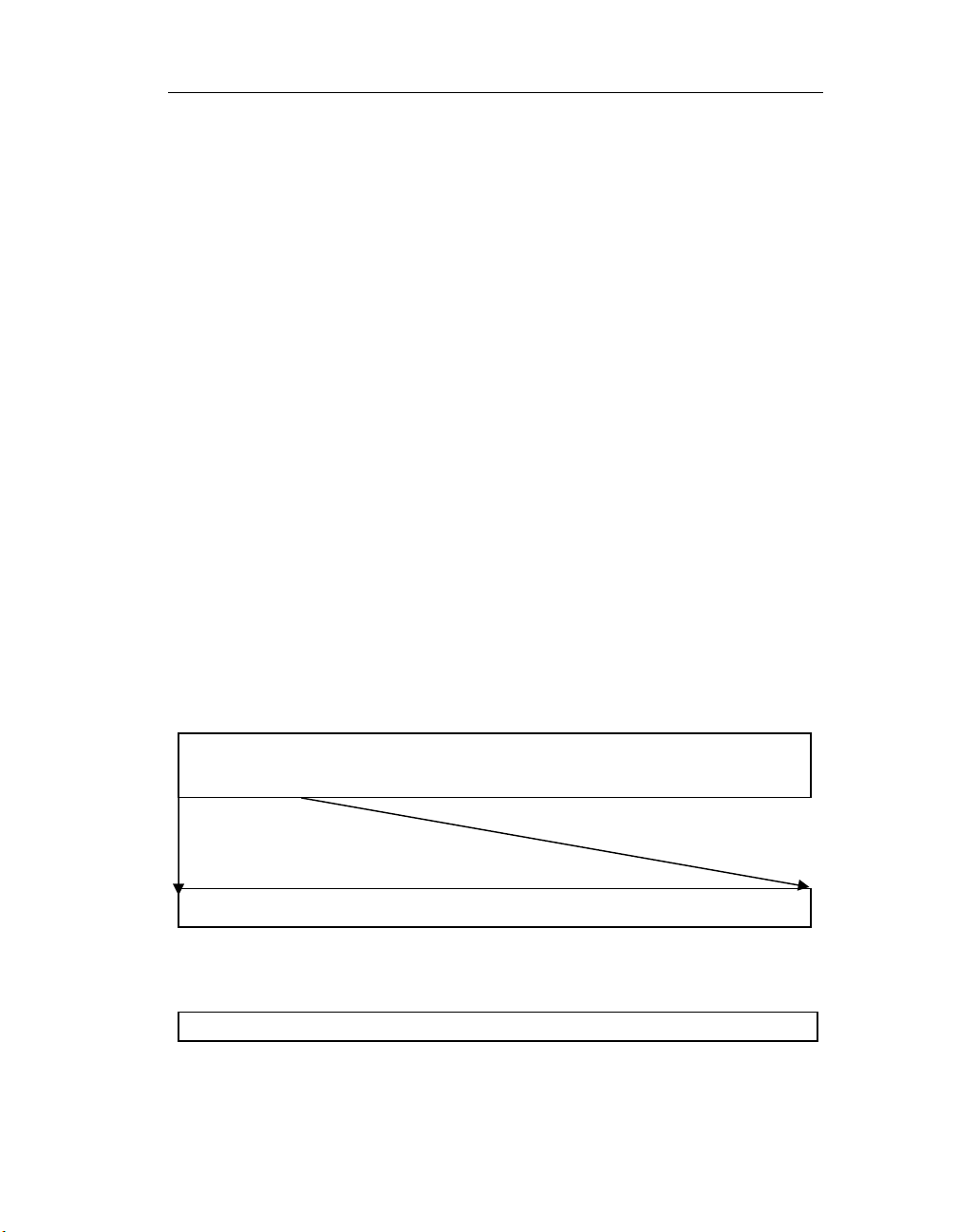
Chapter 3: Analog Input Subsystem Functions
Analog Input Subsystem Functions
Analog Input immediate mode functions
Analog input immediate (or synchronous) mode functions allow to access
to all resources of the PowerDAQ analog input subsystem.
The following commands are included:
• to reset analog input subsystem state
• set up configuration (including input range and mode, type of
clocking and triggering),
• clock conversion and channel list start
• clock start/stop trigger line
• retrieve samples from ADC FIFO
• set DMA transfer size and transfer samples using DMA
• clear and reset both FIFOs
Data stream formats.
Each two consecutive bytes contain a single sample from the A/D converter.
Data is stored repeatedly sample by sample for all channels in the channel
list. (Tables shows a PowerDAQ 16-bit board data format. For PowerDAQ
12-bit boards, only 12 LSBs (Least Significant Bits) are valid. PowerDAQ II
boards automatically place zeroes in any unused bit locations.)
Data Format Table for a 16-bit Board
1st channel 2nd channel … last channel 1st channel
sample sample sample sample
bit15 bit14 bit13 bit12 bit11 bit10 bit9 bit bit7 bit6 bit5 bit4 bit3 bit2 bit1 bit0
PowerDAQ II 12-bit data format
bit15 bit14 bit13 bit12 bit11 bit10 bit9 bit8 bit7 bit6 bit5 bit4 0x0 0x0 0x0 0x0
51
Page 56
Chapter 3: Analog Input Subsystem Functions
PowerDAQ II 14-bit data format
bit15 bit14 bit13 bit12 bit11 bit10 bit9 bit8 bit7 bit6 bit5 bit4 bit3 bit2 0x0 0x0
PowerDAQ II 16-bit data format
bit15 bit14 bit13 bit12 bit11 bit10 bit9 bit8 bit7 bit6 bit5 bit4 bit3 bit2 bit1 bit0
The following calculations should be performed to convert the raw, stored
hexadecimal data to scaled (Voltage) data:
Determine the value of a single bit (“bit weight”) in Volts depending on the
input range.
12-bit PowerDAQ
(span)/4096
12,14 and 16-bit PowerDAQ
II, 16-bit PowerDAQ
(span)/65535
0 - 5V unipolar
0.001221 Volts/bit 0.000076295 Volts/bit
(5V span)
0 - 10V unipolar
0.002442 Volts/bit 0.000152590 Volts/bit
(10V span)
+/-5V bipolar
0.002442 Volts/bit 0.000152590 Volts/bit
(10V span)
+/-10V bipolar
0.004884 Volts/bit 0.000305180 Volts/bit
(20V span)
Table 1: Bit Weight vs. Input Range
Determine the “zero offset” which depends on the input range selected.
5V, 10V unipolar 0
+/-5V biploar -5V
+/-10V biploar -10V
Table 2: Displacement vs. Input Range
1. Perform an arithmetical AND with 0h0FFF for 12-bit PowerDAQ boards
(Go to the step 4 for 16-bit PowerDAQ and all PowerDAQ II boards)
52
Page 57
Chapter 3: Analog Input Subsystem Functions
2. Perform an arithmetical XOR with 0h0800 for PowerDAQ 12-bit boards
and with 0h8000 for all PowerDAQ II and PowerDAQ 16-bit boards
3. Multiply by the “bit weight” from step 1
4. Add the “zero offset” from step 2
5. If a gain other than 1 was used for a selected channel, divide the value
received by the gain factor (Doing this step last guarantees the maximal
data accuracy.)
6. To convert voltage into analog output value you can use following
formulas:
For 12-bit PowerDAQ board:
Value = (((HexData AND 0xFFF) XOR 0x800) * BitWeight + Displacement)
/ Gain
For all other models
Value = ((HexData XOR 0x8000) * BitWeight + Displacement) / Gain
Win32 Win16 Linux RTLinux QNX
Function name AIn Reset
Function Reset analog input subsystem
Returns 1 if success, 0 if failure (Linux: 0 – success, negative if
error occurred)
Syntax:
Win32 API BOOL _PdAInReset(HANDLE hAdapter, DWORD
*pError);
Win16 API BOOL _PdAInReset(HANDLE hAdapter, LPDWORD
lpError);
Linux API int _PdAInReset(int board, DWORD *pError);
RTLinux API int pd_ain_reset(int board);
QNX int pd_ain_reset(int board);
This function resets the analog input subsystem: trigger and clock settings,
channel list, ADC FIFOs, all state machines. To continue analog input
operation after this function has been called you have to re-configure the
board.
Input parameters:
HANDLE hAdapter – handle to adapter (Win)
int board – file descriptor of the subsystem (Linux)
53
Page 58
Chapter 3: Analog Input Subsystem Functions
Output parameters:
DWORD* pError – error code on failure
Win32 Win16 Linux RTLinux QNX
Function name AIn Set Config
Function Sets analog input subsystem configuration for
immediate mode
Returns 1 if success, 0 if failure (Linux: 0 – success, negative if
error occurred)
Syntax:
Win32 API BOOL _PdAInSetCfg(HANDLE hAdapter, DWORD
*pError, DWORD dwAInCfg, DWORD dwAInPreTrig,
DWORD dwAInPostTrig);
Win16 API BOOL _PdAInSetCfg(HANDLE hAdapter, LPDWORD
lpError, DWORD dwAInCfg, DWORD dwAInPreTrig,
DWORD dwAInPostTrig);
Linux API int _PdAInSetCfg(int handle, DWORD dwAInCfg,
DWORD dwAInPreTrig, DWORD dwAInPostTrig);
RTLinux API int pd_ain_set_config(int board, u32 dwAInCfg, u32
AInPreTrig, u32 AInPostTrig);
QNX int pd_ain_set_config(int board, u32 dwAInCfg, u32
AInPreTrig, u32 AInPostTrig);
This function sets analog input subsystem configuration: input mode,
trigger and clock settings. This command is valid only when the AIn
subsystem is in the configuration state (acquisition disabled).
Input parameters:
HANDLE hAdapter – handle to adapter (Win)
int board – file descriptor of the subsystem (Linux)
DWORD dwAInCfg - analog input configuration word
AIn Subsystem Configuration (AInCfg) Bits:
AIB_INPMODE // AIn Input Mode (SingleEnded/Differential if set)
AIB_INPTYPE // AIn Input Type (Unipolar/Bipolar if set)
AIB_INPRANGE // AIn Input Range (5V/10V if set)
AIB_CVSTART0 // AIn Conv Start Clk Source (2 bits)
AIB_CVSTART1 // 00 - SW, 01 - internal, 10 - external,
11 - Continuous
AIB_EXTCVS // AIn External Conv Start (Pacer) Clk Edge
(falling edge if set)
54
Page 59

Chapter 3: Analog Input Subsystem Functions
AIB_CLSTART0 // AIn Ch List Start (Burst) Clk Source (2
bits)
AIB_CLSTART1 // 00 - SW, 01 - internal, 10 - external,
11 - Continuous
AIB_EXTCLS // AIn External Ch List Start (Scan) Clk
Edge (falling edge if set)
AIB_INTCVSBASE // AIn Internal Conv Start Clk Base
(11MHz/33Mhz if set)
AIB_INTCLSBASE // AIn Internal Ch List Start Clk Base
(11MHz/33Mhz if set)
AIB_STARTTRIG0 // AIn Start Trigger Source (2 bits)
(SW/External if set)
AIB_STARTTRIG1 // rising edge / falling edge if set
AIB_STOPTRIG0 // AIn Stop Trigger Source (2 bits)
(SW/External if set)
AIB_STOPTRIG1 // rising edge / falling edge if set
DWORD dwAInPreTrig – reserved. Always 0
DWORD dwAOutPreTrig – reserved. Always 0
Output parameters:
DWORD* pError – error code on failure
Mode and range table selection:
Input Mode Constant
Single-Ended, 0..5V 0
Single-Ended, 0..10V AIB_INPRANGE
Single-Ended, -5..+5V AIB_INPTYPE
Single-Ended, -10..+10V AIB_INPTYPE + AIB_INPRANGE
Differential, 0..5V AIB_INPMODE
Differential, 0..10V AIB_INPMODE + AIB_INPRANGE
Differential, -5..+5V AIB_INPMODE + AIB_INPTYPE
Differential, -10..+10V AIB_INPMODE + AIB_INPTYPE +
AIB_INPRANGE
Triggering mode table selection:
The Analog input subsystem needs a trigger signal to start and stop
acquisition. The Trigger signal is selectable. It can be either software
command or an external pulse. External trigger is edge-sensitive. You can
select rising or falling edge to be active. If the board is set up to start on an
external trigger, all clocks will be ignored until the pulse is detected.
Acquisition continues until the stop trigger is detected.
55
Page 60
Chapter 3: Analog Input Subsystem Functions
Trigger type Configuration
Start trigger rising edge AOB_STARTTRIG0
Start trigger falling edge AOB_STARTTRIG0 + AOB_STARTTRIG1
Stop trigger rising edge AOB_STOPTRIG0
Stop trigger falling edge AOB_ STOPTRIG0+ AOB_ STOPTRIG1
Software trigger 0 (default mode is software trigger if bits are
not set)
Clocking
The PowerDAQ board has two selectable base frequencies (11 MHz and 33
MHz) to clock acquisition. Lower frequencies are obtained by dividing the
base frequency by a 24-bit number (from 1 to 16M).
To calculate the result frequency use the following formula:
Acquisition Rate = Base Frequency / (divisor + 1)
To calculate the divisor use:
Divisor = (Base Frequency/Acquisition Rate)-1
Acquisition is clocked by two signals: conversion start (CV Start) and
channel list start (CL Start). You require both of these signals to start
acquisition.
There are four selectable sources for these clocks:
Software command
Internal timebase
External clock
Continuous clocking (or self-retriggerable clock)
Additionally for internal or external clocks, an active edge (rising or falling)
can be selected.
Note: The PowerDAQ board will generate an error condition each time a
clock signal is applied, before the board is ready to process it. For example, if
you clock the board with a clock frequency higher than the rated aggregate
rate, the board reports a CV/CL start error.
The CV Start clock starts the A/D conversion. The CL Start clock starts the
channel list execution. The CV Start clocks are ignored until the CL Start
pulse is sensed. If any clock is switched to continuous clocking, it retriggers itself immediately after board is ready to process it.
56
Page 61
Chapter 3: Analog Input Subsystem Functions
Clock combination Typical use
CL Clock
source
SW Continuous Acquire one set of data
Internal Continuous Continuous acquisition
External Continuous Continuous acquisition
Continuous Continuous Performs acquisition at
Continuous
or SW
CV Clock
source
Internal Preferable for MF
points (one scan). SW
clock causes channel list
to be executed once. The
board will wait until next
CL clock comes before
restarting.
with accurate timebase.
After each CL Clock
pulse, the channel list is
executed at the
maximum acquisition
rate. This is the most
useful mode.
when each run of the
channel list is triggered
by the external signal.
This mode is used to
synchronize external
events with scans.
maximum speed
possible. Less accurate
than using the timebase.
boards. Do not used for
MFS board. You can
select the specific time
between conversions.
Use this type of clocking
when you want to
increase settling time
between acquisitions
especially when your
signal source has high
output impedance.
Configuration
AIB_CVSTART0+
AIB_CVSTART1
AIB_CLSTART0+
AIB_CVSTART0+
AIB_CVSTART1
AIB_CLSTART1+
AIB_CVSTART0+
AIB_CVSTART1
AIB_CLSTART0+
AIB_CLSTART1+
AIB_CVSTART0+
AIB_CVSTART1
AIB_CLSTART0+
AIB_CLSTART1+
AIB_CVSTART0+
or
AIB_CVSTART0
57
Page 62
Chapter 3: Analog Input Subsystem Functions
Continuous External MF boards only. Useful
when one channel is
acquired and you want
to start acquisition
exactly at the external
pulse edge.
Internal Internal Rarely used. MF boards
only. Useful with slow
scan rates and you need
to provide exact time
between conversions.
External External Rarely used. Gives full
control of the boards
timing to the external
device
SW SW Rarely used. Gives full
control of the boards
timing to your software
Win32 Win16 Linux RTLinux QNX
Function name AIn Set Conversion Clock
Function Sets analog input subsystem conversion clock
frequency
Returns 1 if success, 0 if failure (Linux: 0 – success, negative if
error occurred)
Syntax:
Win32 API BOOL _PdAInSetCvClk(HANDLE hAdapter, DWORD
*pError, DWORD dwClkDiv);
Win16 API BOOL _PdAInSetCvClk(HANDLE hAdapter, LPDWORD
lpError, DWORD dwClkDiv);
Linux API int _PdAInSetCvClk(int handle, DWORD dwClkDiv);
RTLinux API int pd_ain_set_cv_clock(int board, u32 clock_divisor);
QNX int pd_ain_set_cv_clock(int board, u32 clock_divisor);
Input parameters:
HANDLE hAdapter – handle to adapter (Win)
int board – file descriptor of the subsystem (Linux)
DWORD dwClkDiv - AIn conversion start clock divider
The function set internal AIn Conversion Start (pacer) clock configures the
DSP Timer (TMR0) to generate a clock signal using the specified divider
AIB_CLSTART0+
AIB_CLSTART1+
AIB_CVSTART1
AIB_CLSTART0+
AIB_CVSTART0
AIB_CLSTART1+
AIB_CVSTART1
0
58
Page 63
Chapter 3: Analog Input Subsystem Functions
from either a 11.0 MHz or 33.0 MHz base clock frequency (selected in
_PdAInSetCfg).
• Configure AIn Conv Start clock Source to Internal in purpose to utilize
internal AIn Conversion Start (pacer) clock: AIB_CVSTART0
• Use AIB_INTCVSBASE to switch between Internal Conversion Start Clock
Base (11MHz/33Mhz if the bit is set)
• Divisor = ([Base Frequency] / [Desired Sampling Rate]) - 1;
Win32 Win16 Linux RTLinux QNX
Function name AIn Set Scan Clock
Function Sets analog input subsystem scan clock frequency
Returns 1 if success, 0 if failure (Linux: 0 – success, negative if
error occurred)
Syntax:
Win32 API BOOL _PdAInSetClClk(HANDLE hAdapter, DWORD
*pError, DWORD dwClkDiv);
Win16 API BOOL _PdAInSetClClk(HANDLE hAdapter, LPDWORD
lpError, DWORD dwClkDiv);
Linux API Int _PdAInSetClClk(int handle, DWORD dwClkDiv);
RTLinux API Int pd_ain_set_cl_clock(int board, u32 clock_divisor);
QNX Int pd_ain_set_cl_clock(int board, u32 clock_divisor);
Input parameters:
HANDLE hAdapter – handle to adapter (Win)
int board – file descriptor of the subsystem (Linux)
DWORD dwClkDiv - AIn scan start clock divider
The set internal AIn Channel List Start (scan) clock configures the DSP
Timer (TMR1) to generate a clock signal using the specified divider from
either a 11.0 MHz or 33.0 MHz base clock frequency (selected in
_PdAInSetCfg).
• Configure AIn CL Start clock Source to Internal in purpose to utilize
internal AIn Conversion Start (scan) clock: AIB_CLSTART0
• Use AIB_INTCLSBASE to switch between Internal Conversion Start Clock
Base (11MHz/33Mhz if the bit is set)
• Divisor = ([Base Frequency] / [Desired Sampling Rate]) - 1;
59
Page 64

Chapter 3: Analog Input Subsystem Functions
Win32 Win16 Linux RTLinux QNX
Function name AIn Set Channel List
Function Sets analog input subsystem channel list
Returns 1 if success, 0 if failure (Linux: 0 – success, negative if
error occurred)
Syntax:
Win32 API BOOL _PdAInSetChList(HANDLE hAdapter, DWORD
*pError, DWORD dwCh, DWORD *pdwChList);
Win16 API BOOL _PdAInSetChList(HANDLE hAdapter, LPDWORD
lpError, DWORD dwCh, LPDWORD lpdwChList);
Linux API int _PdAInSetChList(int handle, DWORD dwCh,
DWORD *pdwChList);
RTLinux API int pd_ain_set_channel_list(int board, u32
num_entries, u32 list[]);
QNX int pd_ain_set_channel_list(int board, u32
num_entries, u32 list[]);
Input parameters (Win, Linux):
HANDLE hAdapter – handle to adapter (Win)
int board – file descriptor of the subsystem (Linux)
DWORD dwCh – number of channels in list
DWORD *pdwChList – channel list data array
Input parameters (RTLinux, QNX):
int board – file descriptor of the subsystem (Linux)
u32 num_entries – number of channels in list
u32 list[] – channel list data array
The set channel list command programs the ADC Channel/Gain List. The
ADC Channel List can contain from 1 to 256 channel entries in the base
configuration with 4096 entries as an option. Writing a Channel List block
clears and overwrites the previous settings. Writing a channel list with 0
channel entries clears the channel list. There is no limit to the number of
entries that can be written to the channel list FIFO. You need to check CL
size is your application (up to 256 entries).
Configuration data word for each channel includes the channel mux
selection, gain, and slow bit setting.
Following macros are useful to program channel list (powerdaq.h)
60
Page 65
Chapter 3: Analog Input Subsystem Functions
// Macros for constructing Channel List entries.
#define CHAN(c) ((c) & 0x3f)
#define GAIN(g) (((g) & 0x3) << 6)
#define SLOW (1<<8)
#define CHLIST_ENT(c,g,s) (CHAN(c) | GAIN(g) | ((s) ? SLOW :
0))
Win32 Win16 Linux RTLinux QNX
Function name AIn Set Enable Conversion Bit
Function Sets analog input subsystem enable conversion bit
Returns 1 if success, 0 if failure (Linux: 0 – success, negative if
error occurred)
Syntax:
Win32 API BOOL _PdAInEnableConv(HANDLE hAdapter, DWORD
*pError, DWORD dwEnable);
Win16 API BOOL _PdAInEnableConv(HANDLE hAdapter,
LPDWORD lpError, DWORD dwEnable);
Linux API int _PdAInEnableConv(int handle, DWORD dwEnable);
RTLinux API int pd_ain_set_enable_conversion(int board, int
enable);
QNX int pd_ain_set_enable_conversion(int board, int
enable);
Input parameters:
HANDLE hAdapter – handle to adapter (Win)
int board – file descriptor of the subsystem (Linux)
DWORD dwEnable – 0: disable, 1: enable AIn conversions
The enable AIn conversions command enables or disables AIn conversions
irrespective of the AIn Conversion Start or AIn Channel List Start signals.
This command permits completing AIn configuration before the subsystem
responds to the Start trigger set up in AIn Set Configuration call.
When dwEnable = 0 AIn subsystem Start Trigger is disabled and ignored.
Conversion in progress will not be interrupted but the start trigger is
disabled from retriggering the subsystem again. When dwEnable = 1 AIn
subsystem Start Trigger is enabled and data acquisition will start on the
first valid AIn start trigger.
61
Page 66
Chapter 3: Analog Input Subsystem Functions
Win32 Win16 Linux RTLinux QNX
Function name AIn Set Events
Function Sets analog input subsystem events (when to fire irq)
Returns 1 if success, 0 if failure (Linux: 0 – success, negative if
error occurred)
Syntax:
Win32 API BOOL _PdAInSetEvent(HANDLE hAdapter, DWORD
*pError, DWORD dwEvents);
Win16 API BOOL _PdAInSetEvent(HANDLE hAdapter, LPDWORD
lpError, DWORD dwEvents);
Linux API int _PdAInSetEvents(int handle, DWORD dwEvents);
RTLinux API int pd_ain_set_events (int board, u32 dwEvents);
QNX int pd_ain_set_events (int board, u32 dwEvents);
Input parameters (Win, Linux):
HANDLE hAdapter – handle to adapter (Win)
int board – file descriptor of the subsystem (Linux)
DWORD dwEvents – AInIntrStat Event configuration word
Set selected AIn AInIntrStat event bits enabling/disabling and/or clearing
individual firmware level events, thereby re-enabling the event interrupts.
AInIntrStat Bit Settings:
AIB_xxxxIm bits: 0 = disable, 1 = enable interrupt
AIB_xxxxSC bits: 0 = clear interrupt, 1 = no change
Note: Used automatically inside the driver in buffered mode, rarely used in
user code in immediate mode.
AInIntrStat event word format is defined in pdfw_def.h
Win32 Win16 Linux RTLinux QNX
Function name AIn Get Status
Function Gets analog input subsystem status
Returns 1 if success, 0 if failure (Linux: 0 – success, negative if
error occurred)
Syntax:
Win32 API BOOL _PdAInGetStatus(HANDLE hAdapter, DWORD
*pError, DWORD *pdwStatus);
Win16 API BOOL _PdAInGetStatus(HANDLE hAdapter, LPDWORD
lpError, LPDWORD lpdwStatus);
Linux API int _PdAInGetStatus(int board);
RTLinux API int pd_ain_get_status(int board, u32* status);
QNX int pd_ain_get_status(int board, u32* status);
62
Page 67
Chapter 3: Analog Input Subsystem Functions
Input parameters:
HANDLE hAdapter – handle to adapter (Win)
int board – file descriptor of the subsystem (Linux)
DWORD* dwStatus – AIn Event/Status word
DWORD* pError – error code
The AIn Get Status command obtains the current status and events,
including error events, of the AOut subsystem. Used automatically inside
the driver in buffered mode, rarely used in user code in immediate mode.
See pdfw_def.h for the AInIntrStat event word format.
Win32 Win16 Linux RTLinux QNX
Function name AIn Software Start Trigger
Function Pulse start trigger line when analog input is configured
to use software trigger start
Returns 1 if success, 0 if failure (Linux: 0 – success, negative if
error occurred)
Syntax:
Win32 API BOOL _PdAInSwStartTrig(HANDLE hAdapter, DWORD
*pError);
Win16 API BOOL _PdAInSwStartTrig(HANDLE hAdapter,
LPDWORD lpError);
Linux API int _PdAInSwStartTrig(int board);
RTLinux API int pd_ain_sw_start_trigger(int board);
QNX int pd_ain_sw_start_trigger(int board);
Input parameters:
HANDLE hAdapter – handle to adapter (Win)
int board – file descriptor of the subsystem (Linux)
DWORD* pError – error code
The SW AIn start trigger command triggers the AIn Start event to start
sample acquisition.AIn Start trigger should be in software mode (bits are
not set, see _PdAInSetCfg how to set up start trigger).
63
Page 68
Chapter 3: Analog Input Subsystem Functions
Win32 Win16 Linux RTLinux QNX
Function
name
Function Pulse stop trigger line when analog input is configured
Returns 1 if success, 0 if failure (Linux: 0 – success, negative if
Syntax:
Win32 API BOOL _PdAInSwStopTrig(HANDLE hAdapter, DWORD
Win16 API BOOL _PdAInSwStopTrig(HANDLE hAdapter, LPDWORD
Linux API int _PdAInSwStopTrig(HANDLE hAdapter, DWORD
RTLinux API int pd_ain_sw_stop_trigger(int board);
QNX int pd_ain_sw_stop_trigger(int board);
Input parameters:
HANDLE hAdapter – handle to adapter (Win)
int board – file descriptor of the subsystem (Linux)
DWORD* pError – error code
The SW AIn stop trigger command triggers the AIn Stop event to stop
sample acquisition. AIn Stop trigger should be in software mode (bits are
not set, see _PdAInSetCfg how to set up start trigger). If clocks are not
disabled, SW stop trigger allows board to complete started channel list. This
means that you can use start/stop trigger to control acquisition without risk
of losing samples.
Win32 Win16 Linux RTLinux QNX
Function name AIn Software Conversion Clock
Function Pulse conversion clock line once when analog input is
Returns 1 if success, 0 if failure (Linux: 0 – success, negative if
Syntax:
Win32 API BOOL _PdAInSwCvStart(HANDLE hAdapter, DWORD
Win16 API BOOL _PdAInSwCvStart(HANDLE hAdapter, LPDWORD
Linux API int _PdAInSwCvStart(int board);
RTLinux API int pd_ain_sw_cv_start(int board);
QNX int pd_ain_sw_cv_start(int board);
AIn Software Stop Trigger
to use software trigger start
error occurred)
*pError);
lpError);
*pError);
configured to use software conversion clock start
error occurred)
*pError);
lpError);
64
Page 69
Chapter 3: Analog Input Subsystem Functions
Input parameters:
HANDLE hAdapter – handle to adapter (Win)
int board – file descriptor of the subsystem (Linux)
DWORD* pError – error code
The SW AIn conversion start command pulses the ADC Conversion Start
signal. AIn CV clock should be configured into software clock mode (see
_PdAInSetCfg for details).
Note: Do not expect to receive samples immediately after issuing this
command. It takes 1/Rate seconds to convert data. You should put a delay
between software clocking and retrieving data from the FIFO.
Win32 Win16 Linux RTLinux QNX
Function name AIn Software Channel List (scan) Clock
Function Pulse channel list (scan) clock line once when analog
input is configured to use software conversion clock
start
Returns 1 if success, 0 if failure (Linux: 0 – success, negative if
error occurred)
Syntax:
Win32 API BOOL _PdAInSwClStart(HANDLE hAdapter, DWORD
*pError);
Win16 API BOOL _PdAInSwClStart(HANDLE hAdapter, LPDWORD
lpError);
Linux API int _PdAInSwClStart(int board);
RTLinux API int pd_ain_sw_cl_start(int board);
QNX int pd_ain_sw_cl_start(int board);
Input parameters:
HANDLE hAdapter – handle to adapter (Win)
int board – file descriptor of the subsystem (Linux)
DWORD* pError – error code
The SW AIn channel list start command pulses the ADC Conversion Start
signal. AIn CL clock should be configured into software clock mode (see
_PdAInSetCfg for details).
65
Page 70
Chapter 3: Analog Input Subsystem Functions
Win32 Win16 Linux RTLinux QNX
Function name AIn Channel List Reset
Function Resets channel list (set to the first channel
programmed)
Returns 1 if success, 0 if failure (Linux: 0 – success, negative if
error occurred)
Syntax:
Win32 API BOOL _PdAInResetCl(HANDLE hAdapter, DWORD
*pError);
Win16 API BOOL _PdAInResetCl(HANDLE hAdapter, LPDWORD
lpError);
Linux API int _PdAInResetCl(int board);
RTLinux API int pd_ain_reset_cl(int board);
QNX int pd_ain_reset_cl(int board);
Input parameters:
HANDLE hAdapter – handle to adapter (Win)
int board – file descriptor of the subsystem (Linux)
DWORD* pError – error code
The reset AIn channel list command resets the ADC channel list to the first
channel in the list. This command is similar to the SW Channel List Start,
but does not enable the list for conversions.
Win32 Win16 Linux RTLinux QNX
Function name Clear ADC FIFO
Function Discard all samples from ADC FIFO
Returns 1 if success, 0 if failure (Linux: 0 – success, negative if
error occurred)
Syntax:
Win32 API BOOL _PdAInClearData(HANDLE hAdapter, DWORD
*pError);
Win16 API BOOL _PdAInClearData(HANDLE hAdapter, LPDWORD
lpError);
Linux API int _PdAInResetClearData(int board);
RTLinux API int pd_ain_clear_data(int board);
QNX int pd_ain_clear_data(int board);
Input parameters:
HANDLE hAdapter – handle to adapter (Win)
int board – file descriptor of the subsystem (Linux)
DWORD* pError – error code
66
Page 71
Chapter 3: Analog Input Subsystem Functions
The clear all AIn data command clears the ADC FIFO and all AIn data
storage buffers.
Win32 Win16 Linux RTLinux QNX
Function name Get Value
Function Retrieves one sample stored in ADC FIFO
Returns 1 if success, 0 if failure (Linux: 0 – success, negative if
error occurred)
Syntax:
Win32 API BOOL _PdAInGetValue(HANDLE hAdapter, DWORD
*pError, WORD *pwSample);
Win16 API BOOL _PdAInGetValue(HANDLE hAdapter, LPDWORD
lpError, LPWORD lpwSample);
Linux API int _PdAInGetValue(int handle, WORD *pwSample);
RTLinux API int pd_ain_get_value(int board, u16* value);
QNX int pd_ain_get_value(int board, u16* value);
Input parameters:
HANDLE hAdapter – handle to adapter (Win)
int board – file descriptor of the subsystem (Linux)
DWORD* pError – error code on failure
WORD* pwSample – pointer to store sample
The AIn Get Single Value command reads a single value from the ADC
FIFO. Please refer to “User Manual” for data representation.
Win32 Win16 Linux RTLinux QNX
Function name Get Samples
Function Retrieves all sample stored in ADC FIFO
Returns 1 if success, 0 if failure (Linux, QNX: number of
samples received, negative if error occurred)
Syntax:
Win32 API BOOL _PdAInGetSamples(HANDLE hAdapter, DWORD
*pError, DWORD dwMaxBufSize, WORD *pwBuf,
DWORD *pdwSamples);
Win16 API BOOL _PdAInGetSamples(HANDLE hAdapter,
LPDWORD lpError, DWORD dwMaxBufSize, LPWORD
lpwBuf, LPDWORD lpdwSamples);
Linux API int _PdAInGetSamples(int handle,DWORD
dwMaxBufSize, WORD *pwBuf, DWORD
*pdwSamples);
67
Page 72
Chapter 3: Analog Input Subsystem Functions
RTLinux API int pd_ain_get_samples(int board, int max_samples,
uint16_t buffer[]);
QNX int pd_ain_get_samples(int board, int max_samples,
uint16_t buffer[]);
Input parameters (Win):
HANDLE hAdapter – handle to adapter
DWORD* pError – error code on failure
DWORD dwMaxBufSize – maximal number of samples to receive
WORD* pwBuf – buffer to store data
DWORD* pdwSamples – pointer to store the number of samples
transferred
Input parameters (Linux):
int handle – file descriptor of the subsystem
DWORD dwMaxBufSize - maximal number of samples to receive
WORD* pwBuf – buffer to store data
DWORD* pdwSamples – pointer to store the number of samples
transferred
Input parameters (RTLinux, QNX):
int board – board number
int max_samples - maximal number of samples to receive
uint16_t buffer[] buffer to store data
Returns: number of samples transferred of negative value on error
Output parameter:
Number of samples transferred.
The AIn Get Samples command reads upto nMaxBufSize samples from the
ADC FIFO until it is empty. Each sample is stored in 16 bits (signed short
format).
Win32 Linux RTLinux QNX
Function name Get Samples using DMA transfer
Function Retrieves sample stored in ADC FIFO
Returns 1 if success, 0 if failure (Linux, QNX: number of
samples received, negative if error occurred)
Syntax:
Win32 API BOOL _PdAInGetXFerSamples(HANDLE hAdapter,
DWORD *pError, DWORD dwMaxBufSize, WORD
*pwBuf, DWORD *pdwSamples);
68
Page 73
Chapter 3: Analog Input Subsystem Functions
Linux API int _PdAInGetSamples(int handle,DWORD
dwMaxBufSize, WORD *pwBuf, DWORD
*pdwSamples);
RTLinux API int pd_ain_get_xfer_samples(int board, uint16_t*
buffer);
QNX int pd_ain_get_xfer_samples(int board, uint16_t*
buffer);
Input parameters (Win):
HANDLE hAdapter – handle to adapter
DWORD* pError – error code on failure
DWORD dwMaxBufSize – maximal number of samples to receive
WORD* pwBuf – buffer to store data
DWORD* pdwSamples – pointer to store the number of samples
transferred
Input parameters (Linux):
int handle – file descriptor of the subsystem
DWORD dwMaxBufSize - maximal number of samples to receive
WORD* pwBuf – buffer to store data
DWORD* pdwSamples – pointer to store the number of samples
transferred
Input parameters (RTLinux, QNX):
int board – board number
int max_samples - maximal number of samples to receive
uint16_t buffer[] buffer to store data
Returns: number of samples transferred of negative value on error
Output parameter:
Number of samples transferred.
The AIn Get Samples command reads upto nMaxBufSize samples from the
ADC FIFO until it is empty.
Differences between _PdAInGetSamples and _PdAInGetXFerSamples:
_PdAInGetSamples transfers sample-by-sample from the ADC FIFO and
checks the FIFO empty flag every time. _PdAInGetXFerSamples transfers
data from the ADC FIFO using DMA in bursts. The transfer size can be
selected using the _PdAInSetXferSize function. The selected size must be
less or equal to the number of samples stored in the ADC FIFO at the time
you call _PdAInGetXFerSamples. If the FIFO does not contain enough
samples, the buffer is padded with the last available sample.
69
Page 74
Chapter 3: Analog Input Subsystem Functions
_PdAInGetXFerSamples is a good function to use for RT-Linux or QNX realtime tasks, when the number of samples to retrieve is predefined.
Win32 Linux RTLinux QNX
Function name Get Samples using DMA transfer
Function Retrieves sample stored in ADC FIFO
Returns 1 if success, 0 if failure (Linux, QNX: 0 if succeed,
negative if error occurred)
Syntax:
Win32 API BOOL _PdAInSetXferSize (HANDLE hAdapter, DWORD
*pError, DWORD pdwSamples);
Linux API int _PdAInSetXferSize(int handle, DWORD size)
RTLinux API int pd_ain_set_xfer_size(int board, u32 size);
QNX int pd_ain_set_xfer_size(int board, u32 size);
Input parameters:
HANDLE hAdapter – handle to adapter (Win)
int handle – file descriptor of the subsystem (Linux)
DWORD size – size of the DMA transfer (16, 32, ..., [ADC FIFO Size])
Set up DMA transfer burst size. It can only be a power of two starting
from 2. There is no need to use XFer is you are transferring less then 16
samples.
Warning: Do not use this function with asynchronous (buffered) mode. It
will hang up your PC. Use _PdAInReset to return to default settings
Analog Input buffered mode functions
Buffered mode analog input is available for Windows and Linux platforms.
It uses a big buffer (Advanced Circular Buffer – ACB) allocated in virtual
memory and locked into physical pages to store data. It allows you to
process very high acquisition rates on non-realtime OSes. QNX and RTLinux
driver implementations do not support buffered mode due to it realtime
nature.
Analog Input buffered mode function set includes:
• Buffer management functions (see chapter 2).
• Initialization/Cleanup functions
• Event management functions
• Data retreiving functions
70
Page 75
Chapter 3: Analog Input Subsystem Functions
See _PdAInSetCfg() for analog input configuration information and
“PowerDAQ User Manual”.
Win32 Win16 Linux
Function name AIn Async Init
Function Initialize analog input asynchronous (buffered)
operation
Returns 1 if success, 0 if failure (Linux: 0 if succeed, negative if
error occurred)
Syntax:
Win32 API BOOL _PdAInAsyncInit(HANDLE hAdapter, DWORD
*pError, ULONG dwAInCfg, ULONG
dwAInPreTrigCount, ULONG dwAInPostTrigCount,
ULONG dwAInCvClkDiv, ULONG dwAInClClkDiv,
ULONG dwEventsNotify, ULONG dwChListChan,
PULONG pdwChList);
Win16 API BOOL _PdAInAsyncInit(HANDLE hAdapter, LPDWORD
lpError,
DWORD dwAInCfg, DWORD dwAInPreTrigCount,
DWORD dwAInPostTrigCount, DWORD dwAInCvClkDiv,
DWORD dwAInClClkDiv, DWORD dwEventsNotify,
DWORD dwChListChan, LPDWORD lpdwChList);
Linux API int _PdAInAsyncInit(int handle, ULONG dwAInCfg,
ULONG dwAInPreTrigCount, ULONG
dwAInPostTrigCount, ULONG dwAInCvClkDiv, ULONG
dwAInClClkDiv, ULONG dwEventsNotify, ULONG
dwChListChan, PULONG pdwChList);
The AIn Initialize Asynchronous Buffered Acquisition function initializes the
configuration.
This function does NO checking on the hardware configuration parameters,
it is the responsibility of the DLL to verify that the parameters are valid for
the device type being configured. It program must pass correct parameters
to the function based on the hardware used.
Input parameters:
HANDLE hAdapter – handle to adapter (Win)
int handle – file descriptor of the subsystem (Linux)
PDWORD pError – error code on failure
DWORD dwAInCfg – analog input configuration DWORD (see
pdfw_def.h)
71
Page 76

Chapter 3: Analog Input Subsystem Functions
AIn Subsystem Configuration (AInCfg) Bits (see _PdAInSetCfg for
additional information):
AIB_INPMODE – AIn Input Mode (Single-Ended/Differential if set)
AIB_INPTYPE – AIn Input Type (Unipolar/Bipolar if set)
AIB_INPRANGE – AIn Input Range (5V/10V if set)
AIB_CVSTART0 – AIn Conv Start Clk Source (2 bits)
AIB_CVSTART1 – 00 - SW, 01 - internal, 10 - external, 11 - Continuous
AIB_EXTCVS – AIn External Conv Start (Pacer) Clk Edge (falling edge if
set)
AIB_CLSTART0 – AIn Ch List Start (Burst) Clk Source (2 bits)
AIB_CLSTART1 – 00 - SW, 01 - internal, 10 - external, 11 - Continuous
AIB_EXTCLS – AIn External Ch List Start (Burst) Clk Edge
(falling edge if set)
AIB_INTCVSBASE – AIn Internal Conv Start Clk Base (11MHz/33Mhz if set)
AIB_INTCLSBASE – AIn Internal Ch List Start Clk Base (11MHz/33Mhz if
set)
AIB_STARTTRIG0 – AIn Start Trigger Source (2 bits) (SW/External if set)
AIB_STARTTRIG1 – rising edge / falling edge if set
AIB_STOPTRIG0 – AIn Stop Trigger Source (2 bits) (SW/External if set)
AIB_STOPTRIG1 – rising edge / falling edge if set
All other bits are to be used internally
DWORD dwAInPreTrigCount - reserved, keep it 0
DWORD dwAInPostTrigCount – reserved, keep it 0
DWORD dwAInCvClkDiv - sets the value for the conversion (CV) clock
divider. The CV clock can come from either an 11 MHz or 33 MHz base
frequency. The divider then reduces this frequency down to a specific
sampling frequency. Due to a feature in the DSP counter operation, the
divider value needs to be one count less than the value you want to utilize.
dwAInCvClkDiv = (base frequency / acquisition rate) – 1 (I.e. If you want
a divider value of 23, you should set the dwAInCvClkDiv parameter to 22.)
DWORD dwAInClClkDiv - sets the value for the channel list (CL) clock
divider. The CL clock can come from either an 11 MHz or 33 MHz base
frequency. The divider then reduces this frequency down to a specific scan
frequency. Due to a feature in the DSP counter operation, the divider value
needs to be one count lower than the value you want to utilize
If the selected frequency is higher than the possible conversion or scan
rate, the board ignores pulses coming before it is ready to process the next
sample/scan.
72
Page 77
Chapter 3: Analog Input Subsystem Functions
DWORD dwEventsNotify - this flag tells the driver upon which events it
should notify the application. Each bit of the value references a specific
event as listed in the table below.
Event configuration:
EStartTrig – Start trigger received, operation started
eStopTrig – Stop trigger received, operation stopped
eInputTrig – Subsystem specific input trigger (if any)
eDataAvailable – New data available
eScanDone – Scan done (for future use)
eFrameDone – One or more frames are done
eFrameRecycled – Cyclic buffer frame recycled
(i.e. an unread frame is over-written by new data)
eBufferDone – Buffer done
eBufferWrapped – Cyclic buffer wrapped
eConvError – Conversion clock error - pulse came before board is ready to
process it
eScanError – Scan clock error
eBufferError – Buffer over/under run error
eStopped – Operation stopped (possibly because of error)
eTimeout – Operation timed out
eAllEvents – Set/clear all events
DWORD dwAInScanSize - indicates the number of channels in each scan
PDWORD pdwChList - specify the pointer to the channel list array.
Win32 Win16 Linux
Function name AIn Async Term
Function Terminate analog input asynchronous (buffered)
operation
Returns 1 if success, 0 if failure (Linux: 0 if succeed, negative if
error occurred)
Syntax:
Win32 API BOOL _PdAInAsyncTerm(HANDLE hAdapter, DWORD
*pError);
Win16 API BOOL _PdAInAsyncTerm(HANDLE hAdapter,
LPDWORD lpError);
Linux API int _PdAInAsyncTerm(int handle);
The AIn Terminate Asynchronous Buffered Acquisition function terminates
and releases the memory allocated for buffered acquisition.
73
Page 78
Chapter 3: Analog Input Subsystem Functions
Input parameters:
HANDLE hAdapter – handle to adapter (Win)
int handle – file descriptor of the subsystem (Linux)
PDWORD pError – error code on failure
Win32 Win16 Linux
Function name AIn Async Start
Function Starts analog input asynchronous (buffered) operation
Returns 1 if success, 0 if failure (Linux: 0 if succeed, negative if
error occurred)
Syntax:
Win32 API BOOL _PdAInAsyncStart(HANDLE hAdapter, DWORD
*pError);
Win16 API BOOL _PdAInAsyncStart(HANDLE hAdapter, LPDWORD
lpError);
Linux API int _PdAInAsyncStart(int handle);
The AIn Start Asynchronous Buffered Acquisition function starts buffered
acquisition.
Input parameters:
HANDLE hAdapter – handle to adapter (Win)
int handle – file descriptor of the subsystem (Linux)
PDWORD pError – error code on failure
Win32 Win16 Linux
Function name AIn Async Stop
Function Stops analog input asynchronous (buffered) operation
Returns 1 if success, 0 if failure (Linux: 0 if succeed, negative if
error occurred)
Syntax:
Win32 API BOOL _PdAInAsyncStop(HANDLE hAdapter, DWORD
*pError);
Win16 API BOOL _PdAInAsyncStop(HANDLE hAdapter, LPDWORD
lpError);
Linux API int _PdAInAsyncStop(int handle);
The AIn Stop Asynchronous Buffered Acquisition function stops buffered
acquisition.
74
Page 79
Chapter 3: Analog Input Subsystem Functions
Input parameters:
HANDLE hAdapter – handle to adapter (Win)
int handle – file descriptor of the subsystem (Linux)
PDWORD pError – error code on failure
Win32 Linux r3
Function name Get AIn Buffer State
Function Returns current state of analog input buffered
operation
Returns 1 if success, 0 if failure (Linux: 0 if succeed, negative if
error occurred)
Syntax:
Win32 API BOOL _PdAInGetBufState(HANDLE hAdapter, DWORD
*pError, DWORD NumScans, DWORD *pScanIndex,
DWORD *pNumValidScans);
Linux API int _PdAInGetBufState(int handle, DWORD NumScans,
DWORD *pScanIndex, DWORD *pNumValidScans);
Input parameters:
HANDLE hAdapter – handle to adapter (Win)
int handle – file descriptor of the subsystem (Linux)
PDWORD pError – error code on failure
DWORD NumScans – number of scans to get [1..MaxScansInBuffer]
DWORD *pScanIndex – pointer to buffer index of first scan
DWORD *pNumValidScans – pointer to number of valid scans available
The AIn Get Scans function returns the oldest scan index in the DAQ buffer
and releases (recycles) frame(s) of scans that had been obtained
previously.
pScanIndex and pNumValidScans are in scans.
To find out offset of the first sample available use:
WORD* pOffset = pInBuffer + pScanIndex*dwScanSize
If the circular buffer is used and head of the buffer is less than the tail,
the first call to this function returns scans from the tail position to the end
of the buffer. Subsequent calls return scans from the beginning of the
buffer until the head. The user application always receives non-wrapped
chunks of data.
Assume that the buffer has four frames, 256 scans each. Total capacity of
the buffer is 1024 scans. Wraparound mode is used. _PdAInGetBufState()
each time when driver reports eFrameDone event.
75
Page 80
Chapter 3: Analog Input Subsystem Functions
Case # Head Tail Requested ScanIndex ValidScans
1 0 255 1024 0 266
2 266 511 256 266 256
3 522 255 1024 522 502
0 255 1024 0 256
Case 1. Head is less than the tail. All available scans are requested. Function
returns 256+ scans (256 scans of the first frame plus whatever number of
scans acquired between time of notification and _PdAInGetBufState call. In
this example, use 10).
Case 2. Head is less than the tail. Exactly one frame of scans is requested.
Function returns exactly 256 scans.
Case 3. Head is bigger than the tail. Buffer is wrapped around. First call to
the function returns all scans available from the tail to the end of the
buffer. Consecutive calls to the function returns remainder from the
beginning of the buffer to the current tail.
Win32 Linux
Function
name
Function Returns current state of analog input buffered operation
Returns 1 if success, 0 if failure (Linux: 0 if succeed, negative if
Syntax:
Win32 API BOOL _PdAInGetScans(HANDLE hAdapter, DWORD
Linux API int _PdAInGetScans(int handle, DWORD NumScans,
This function is identical to _PdAInGetBufState() and is is used for
compatibility.
Win32
Function name Set AIn Private Event
Returns 1 if success, 0 if failure
Syntax:
Win32 API BOOL _PdAInSetPrivateEvent(HANDLE hAdapter,
Get AIn Buffer State
error occurred)
*pError, DWORD NumScans, DWORD *pScanIndex,
DWORD *pNumValidScans);
DWORD *pScanIndex, DWORD *pNumValidScans);
HANDLE *phNotifyEvent);
76
Page 81
Chapter 3: Analog Input Subsystem Functions
Input parameters:
HANDLE hAdapter – handle to adapter
HANDLE *phNotifyEvent – handle to notification event
The Set Private Event function creates a notification event and sets the
driver to signal the event upon assertion of a user event.
WaitForSingleObject() or WaitForMultipleObjects().
Set event pulses when event situation occurs in analog input subsystem.
Linux specific:
Linux driver provides two ways of event notification: using SIGIO and
blocking read().
See _PdSetAsyncNotify() and _PdWaitForEvent() for details.
Win32
Function name Clear AIn Private Event
Function Frees event object and unregisters it with the driver
Returns 1 if success, 0 if failure
Syntax:
Win32 API BOOL _PdAInClearPrivateEvent(HANDLE hAdapter,
HANDLE *phNotifyEvent);
Input parameters:
HANDLE hAdapter – handle to adapter
HANDLE *phNotifyEvent – handle to notification event
The Clear Private Event function disables signaling of the event by the
driver and closes the notification event handle. This function is to be used
in conjunction with _PdAInSetPrivateEvent().
77
Page 82

4
Analog Output
Subsystem Functions
78
Page 83
Chapter 4: Analog Output Subsystem Functions
Analog Output Subsystem Functions
Analog Output immediate mode functions
(PD2-MF/S boards only)
Analog output immediate (or synchronous) mode functions allow access to
all resources of the PowerDAQ MF(S) analog input subsystem.
Function set includes commands:
• to reset analog output subsystem state
• set up configuration (including type of clocking and triggering),
• clock conversion start
• clock start/stop trigger line
• put samples into DAC FIFO
• set DMA transfer size and transfer samples using DMA
Note: PowerDAQ II AO boards have a separate set of functions with _PdAO
prefix. Do not use functions with _PdAOut prefix for PD2-AO-xx boards
excluding some circumstances defined in this manual. See chapters 4.3 and
4.4 if you have a PD2-AO-xx board.
Win32 Win16 Linux RTLinux QNX
Function name AOut Reset
Function Reset analog output subsystem
Returns 1 if success, 0 if failure (Linux: 0 – success, negative if
error occurred)
Syntax:
Win32 API BOOL _PdAOutReset(HANDLE hAdapter, DWORD
*pError);
Win16 API BOOL _PdAOutReset(HANDLE hAdapter, LPDWORD
lpError);
Linux API int _PdAOutReset(int board, DWORD *pError);
RTLinux API int pd_aout_reset(int board);
QNX int pd_aout_reset(int board);
This function resets the analog output subsystem: trigger and clock
settings, DAC FIFOs, and all state machines. To continue analog input
operation after this function has been called you have to set up the board
again. This will reset voltages at both analog outputs to 0 (zero).
79
Page 84
Chapter 4: Analog Output Subsystem Functions
Input parameters:
HANDLE hAdapter – handle to adapter (Win)
int board – file descriptor of the subsystem (Linux)
Output parameters:
DWORD* pError – error code on failure
Win32 Win16 Linux RTLinux QNX
Function name AOut Set Configuration
Function Configures analog output subsystem
Returns 1 if success, 0 if failure (Linux: 0 – success, negative if
error occurred)
Syntax:
Win32 API BOOL _PdAOutSetCfg(HANDLE hAdapter, DWORD
*pError, DWORD dwAOutCfg, DWORD
dwAOutPostTrig);
Win16 API BOOL _export _loadds _PdAOutSetCfg(HANDLE
hAdapter, LPDWORD lpError, DWORD dwAOutCfg,
DWORD dwAOutPostTrig);
Linux API Int _PdAOutSetCfg(int handle, DWORD dwAOutCfg,
DWORD dwAOutPostTrig);
RTLinux API Int pd_aout_set_config(int board, u32 config, u32
posttrig);
QNX Int pd_aout_set_config(int board, u32 config, u32
posttrig);
Input parameters:
HANDLE hAdapter – handle to adapter (Win)
int board – file descriptor of the subsystem (Linux)
DWORD* pError – error code on failure
DWORD dwAOutCfg – analog output configuration DWORD
DWORD dwAOutPostTrig – reserved, pass 0 to the function
The set AOut configuration command sets the operating configuration of
the AOut subsystem. This command is valid only when the AOut subsystem
is in the configuration state (acquisition disabled).
AOut Subsystem Configuration (AInCfg) Bits:
AOB_CVSTART0 – AOut Conv (Pacer) Start Clk Source (2 bits)
AOB_CVSTART1 – 00 - SW, 01 - internal, 10 - external
80
Page 85
Chapter 4: Analog Output Subsystem Functions
AOB_EXTCVS – AOut External Conversion (Pacer) Clock Edge (Rising edge
if zero/falling edge if set)
AOB_STARTTRIG0 – AOut Start Trigger Source (2 bits) (SW/external if
set)
AOB_STARTTRIG1 – (rising edge if zero/falling edge if set)
AOB_STOPTRIG0 – AOut Stop Trigger Source (2 bits) (SW/external if set)
AOB_STOPTRIG1 – (rising edge if zero/falling edge if set)
AOB_REGENERATE – Switch to regenerate mode - use DAC FIFO as
circular buffer
AOB_AOUT32 – Set this bit if you would like to use regenerate mode with
PD2-AO-xx board
AOB_INTCVSBASE – AOut Internal Conv Start Clk Base (11MHz/33Mhz if
set)
Win32 Win16 Linux RTLinux QNX
Function name AOut Set Conversion Clock
Function Sets analog output subsystem conversion clock
frequency
Returns 1 if success, 0 if failure (Linux: 0 – success, negative if
error occurred)
Syntax:
Win32 API BOOL _PdAOutSetCvClk(HANDLE hAdapter, DWORD
*pError, DWORD dwClkDiv);
Win16 API BOOL _PdAOutSetCvClk(HANDLE hAdapter, LPDWORD
lpError, DWORD dwClkDiv);
Linux API int _PdAOutSetCvClk(int handle, DWORD dwClkDiv);
RTLinux API int pd_aout_set_cv_clock(int board, u32
clock_divisor);
QNX int pd_aout_set_cv_clock(int board, u32
clock_divisor);
Input parameters:
HANDLE hAdapter – handle to adapter (Win)
int board – file descriptor of the subsystem (Linux)
DWORD dwClkDiv - APit conversion start clock divider
This function sets the internal AOut Conversion Start (pacer) clock,
configures the DSP Timer (TMR2) to generate a clock signal using the
specified divider from 11.0 MHz base clock frequency.
• Configure AOut Conv Start clock Source to Internal to utilize
internal Conversion Start (pacer) clock: AOB_CVSTART0
• Divisor = ([11MHz] / [Desired Sampling Rate]) - 1;
81
Page 86
Chapter 4: Analog Output Subsystem Functions
Win32 Win16 Linux RTLinux QNX
Function name AOut Get Status
Function Gets analog output subsystem status
Returns 1 if success, 0 if failure (Linux: 0 – success, negative if
error occurred)
Syntax:
Win32 API BOOL _PdAOutGetStatus(HANDLE hAdapter, DWORD
*pError, DWORD *pdwStatus);
Win16 API BOOL _PdAOutGetStatus(HANDLE hAdapter,
LPDWORD lpError, LPDWORD lpdwStatus);
Linux API int _PdAOutGetStatus(int board);
RTLinux API int pd_aout_get_status(int board, u32* status);
QNX int pd_aout_get_status(int board, u32* status);
Input parameters:
HANDLE hAdapter – handle to adapter (Win)
int board – file descriptor of the subsystem (Linux)
DWORD* pError – error code
DWORD* dwStatus – AOut Event/Status word
The AOut Get Status command obtains the current status and events,
including error events, of the AOut subsystem. This function is used
automatically inside the driver in buffered mode, rarely used in user code in
immediate mode.
See pdfw_def.h for the AOutIntrStat event word format.
Win32 Win16 Linux RTLinux QNX
Function name AOut Set Enable Conversion Bit
Function Sets analog output subsystem enable conversion bit
Returns 1 if success, 0 if failure (Linux: 0 – success, negative if
error occurred)
Syntax:
Win32 API BOOL _PdAOutEnableConv(HANDLE hAdapter,
DWORD *pError, DWORD dwEnable);
Win16 API BOOL _PdAOutEnableConv(HANDLE hAdapter,
LPDWORD lpError, DWORD dwEnable);
Linux API int _PdAOutEnableConv(int handle, DWORD
dwEnable);
RTLinux API int pd_aout_set_enable_conversion(int board, int
enable);
82
Page 87
Chapter 4: Analog Output Subsystem Functions
QNX int pd_aout_set_enable_conversion(int board, int
enable);
Input parameters:
HANDLE hAdapter – handle to adapter (Win)
int board – file descriptor of the subsystem (Linux)
DWORD* pError – error code
DWORD dwEnable – 0: disable, 1: enable AOut conversions
The enable AOut conversions command enables or disables AOut
conversions irrespective of the AOut Conversion Clock signal or Start
Trigger. During configuration and following
an error condition the AOut conversion process is disabled and must be reenabled to perform subsequent conversions.
This command permits the completing AOut configuration before the
subsystem responds to the Start trigger.
PD_AONCVEN = 0: AOut subsystem Start Trigger is disabled and ignored.
Conversion in progress will not be interrupted but the start trigger is
disabled from retriggering the subsystem again.
PD_AONCVEN = 1: AOut subsystem Start Trigger is enabled and D/A
output will start on the first valid AOut start trigger.
Win32 Win16 Linux RTLinux QNX
Function name AOut Software Start Trigger
Function Pulse start trigger line when analog input is configured
to use software trigger start
Returns 1 if success, 0 if failure (Linux: 0 – success, negative if
error occurred)
Syntax:
Win32 API BOOL _PdAInSwStartTrig(HANDLE hAdapter, DWORD
*pError);
Win16 API BOOL _PdAInSwStartTrig(HANDLE hAdapter,
LPDWORD lpError);
Linux API int _PdAInSwStartTrig(int board);
RTLinux API int pd_ain_sw_start_trigger(int board);
QNX int pd_ain_sw_start_trigger(int board);
Input parameters:
HANDLE hAdapter – handle to adapter (Win)
int board – file descriptor of the subsystem (Linux)
83
Page 88
Chapter 4: Analog Output Subsystem Functions
DWORD* pError – error code
The SW AOut start trigger command triggers the AOut Start event to start
value output.
Software trigger should be selected in _PdAOutSetCfg Block mode only.
The SW AOut start trigger command triggers the AOut Start event to start
D/A conversion. AOut Start trigger should be in software mode (bits are
not set, see _PdAOutSetCfg how to set up start trigger).
Win32 Win16 Linux RTLinux QNX
Function name AOut Software Stop Trigger
Function Pulse stop trigger line when analog input is configured
to use software trigger start
Returns 1 if success, 0 if failure (Linux: 0 – success, negative if
error occurred)
Syntax:
Win32 API BOOL _PdAOutSwStopTrig(HANDLE hAdapter, DWORD
*pError);
Win16 API BOOL _PdAOutSwStopTrig(HANDLE hAdapter,
LPDWORD lpError);
Linux API int _PdAOutSwStopTrig(HANDLE hAdapter, DWORD
*pError);
RTLinux API int pd_aout_sw_stop_trigger(int board);
QNX int pd_aout_sw_stop_trigger(int board);
Input parameters:
HANDLE hAdapter – handle to adapter (Win)
int board – file descriptor of the subsystem (Linux)
DWORD* pError – error code
The SW AOut stop trigger command triggers the AOut Stop event to stop
D/A conversion. AIn Stop trigger should be set in software mode (bits are
not set, see _PdAOutSetCfg how to set up start trigger).
Software trigger should be selected in _PdAOutSetCfg block mode only
Win32 Win16 Linux RTLinux QNX
Function name AOut Software Conversion Clock
Function Pulse conversion clock line once when analog input is
configured to use software conversion clock start
84
Page 89
Chapter 4: Analog Output Subsystem Functions
Returns 1 if success, 0 if failure (Linux: 0 – success, negative if
error occurred)
Syntax:
Win32 API BOOL _PdAOutSwCvStart(HANDLE hAdapter, DWORD
*pError);
Win16 API BOOL _PdAOutSwCvStart(HANDLE hAdapter,
LPDWORD lpError);
Linux API int _PdAOutSwCvStart(int board);
RTLinux API int pd_aout_sw_cv_start(int board);
QNX int pd_aout_sw_cv_start(int board);
Input parameters:
HANDLE hAdapter – handle to adapter (Win)
int board – file descriptor of the subsystem (Linux)
DWORD* pError – error code
The SW AOut conversion start command pulses the D/A Conversion Start
signal. Analog output will be set up into buffered mode and the buffer will
be loaded using _PdAOutPutBlock(). AOut CV clock should be configured
to software clock mode (see _PdAOutSetCfg for details). To use this
function you should select SW clock in _PdAOutSetCfg, load buffer using
_PdAOutPutValues with the appropriate number of
values and then clock them out (convert to analog) one by one.
Win32 Win16 Linux RTLinux QNX
Function name Clear DAC FIFO
Function Discard all samples from the DAC FIFO
Returns 1 if success, 0 if failure (Linux: 0 – success, negative if
error occurred)
Syntax:
Win32 API BOOL _PdAOutClearData(HANDLE hAdapter, DWORD
*pError);
Win16 API BOOL _PdAOutClearData(HANDLE hAdapter,
LPDWORD lpError);
Linux API int _PdAOutResetClearData(int board);
RTLinux API int pd_aout_clear_data(int board);
QNX int pd_aout_clear_data(int board);
Input parameters:
HANDLE hAdapter – handle to adapter (Win)
int board – file descriptor of the subsystem (Linux)
DWORD* pError – error code
85
Page 90
Chapter 4: Analog Output Subsystem Functions
The clear all AOut data command clears the DAC latch and all AOut data
storage buffers.
Win32 Win16 Linux RTLinux QNX
Function name AOut Put Value
Function Output one 24-bit value into both AOut channels
Returns 1 if success, 0 if failure (Linux: 0 – success, negative if
error occurred)
Syntax:
Win32 API BOOL _PdAOutPutValue(HANDLE hAdapter, DWORD
*pError, DWORD dwValue);
Win16 API BOOL _PdAOutPutValue(HANDLE hAdapter, LPDWORD
lpError, DWORD dwValue);
Linux API int _PdAOutPutValue(int handle, DWORD dwValue);
RTLinux API int pd_aout_put_value(int board, u32 dwValue);
QNX int pd_aout_put_value(int board, u32 dwValue);
Input parameters:
HANDLE hAdapter – handle to adapter (Win)
int board – file descriptor of the subsystem (Linux)
DWORD* pError – error code
DWORD dwValue – value to write
The AOut put single value command writes a single value to be converted
and output by the specified DAC.
This function works only with PD2-MF(S) boards. To set up the output
value for PD2-AO series, use _PdAO32Write().
There is a fixed Channel List for the analog output on the PD2-MF(S)
boards. The channel list always contains channel 0 and 1 and are updated
simultaneously.
Note: The two channels are updated at the same time, therefore you have to
configure both DACs to the same mode of operation.
Data Format
Unused 1
12-bit output data
for Aout1 1
12-bit output data
for Aout 0
Analog Output Data Format
86
Page 91
Chapter 4: Analog Output Subsystem Functions
The analog outputs have a fixed output range of +/- 10V. Data
representation is straight binary. To convert voltage into binary codes use
the following formula.
HexValue = ((Voltage + 10.0V) / 20.0) * 0xFFF
The two Hex values for Aout channel 0 and 1 respectively can be combined
to write to the analog output as follows:
Value_To_Write = (HexValue1 << 12) OR (HexValue0)
Win32 Win16 Linux RTLinux QNX
Function name AOut Put Block
Function Output one 24-bit value into both AOut channels
Returns 1 if success, 0 if failure (Linux: 0 – success, negative if
error occurred)
Syntax:
Win32 API BOOL _PdAOutPutBlock(HANDLE hAdapter, DWORD
*pError,
DWORD dwValues, DWORD *pdwBuf, DWORD
*pdwCount);
Win16 API BOOL _PdAOutPutBlock(HANDLE hAdapter, LPDWORD
lpError, DWORD dwValues, LPDWORD lpdwBuf,
LPDWORD lpdwCount);
Linux API int _PdAOutPutBlock(int handle, DWORD dwValues,
DWORD *pdwBuf, DWORD *pdwCount);
RTLinux API int pd_aout_put_block(int board, u32 dwNumValues,
u32* pdwBuf, u32* pdwCount);
QNX int pd_aout_put_block(int board, u32 dwNumValues,
u32* pdwBuf, u32* pdwCount);
Input parameters:
HANDLE hAdapter – handle to adapter (Win)
int board – file descriptor of the subsystem (Linux)
DWORD* pError – error code
DWORD dwNumValues – number of values in buf to output
DWORD *pdwBuf – buffer containing values to output
DWORD *pdwCount – number of values successfully written
The AOut put block command writes a block of values to the DAC FIFO
87
Page 92
Chapter 4: Analog Output Subsystem Functions
This function can be used either with PD2-MF(S) or PD2-AO series boards.
To use it with PD2-AO boards AOB_AOUT32 bit should be set in AOut
configuration word. The DAC FIFO size is 2048 samples. If the DAC FIFO is
not empty, the function returns the number of values it was able to write
until the FIFO becomes full.
Analog Output asynchronous mode functions
(PD2-MFx board)
Buffered mode analog output is available for Windows and Linux
platforms. It uses a large buffer (Advanced Circular Buffer – ACB)
allocated in virtual memory and locked into physical pages to store data. It
allows high D/A rates on non-realtime OSes. QNX and RTLinux driver
implementations do not support buffered mode due to its’ realtime nature.
Analog Input buffered mode function set includes:
• Buffer management functions (see chapter 2).
• Initialization/Cleanup functions
• Event management functions
• Data transferring functions
See _PdAOutSetCfg() for analog output configuration information and
“PowerDAQ MF(S) User Manual”.
Win32 Linux r3
Function name AOut Async Init
Function Initialize analog output asynchronous (buffered)
operation
Returns 1 if success, 0 if failure (Linux: 0 if succeed, negative if
error occurred)
Syntax:
Win32 API BOOL _PdAOAsyncInit(HANDLE hAdapter, DWORD
pError, DWORD dwAOutCfg, DWORD
dwAOutCvClkDiv, DWORD dwEventNotify, DWORD
dwChListSize, PDWORD pdwChList);
Linux API int _PdAOAsyncInit(int handle, DWORD dwAOutCfg,
DWORD dwAOutCvClkDiv, DWORD dwEventNotify,
DWORD dwChListSize, PDWORD pdwChList);
Initialize Asynchronous Buffered Acquisition function initializes the
configuration.
88
Page 93

Chapter 4: Analog Output Subsystem Functions
This driver function does NO checking on the hardware configuration
parameters, it is the responsibility of the DLL to verify that the parameters
are valid for the device type being configured.
Input parameters:
HANDLE hAdapter – handle to adapter (Win)
int handle – file descriptor of the subsystem (Linux)
PDWORD pError – error code
DWORD dwAOutCfg – AIn configuration word
DWORD dwAOutCvClkDiv – conv. start clk div.
DWORD dwEventsNotify – subsys user events notif.
dwAOutCfg represents a variety of configuration parameters ( see
pdfw_def.h):
AOut Subsystem Configuration (AInCfg) Bits:
AOB_CVSTART0 – AOut Conv (Pacer) Start Clk Source (2 bits)
AOB_CVSTART1 – 00 - SW, 01 - internal, 10 - external
AOB_EXTCVS – AOut External Conv (Pacer) Clock Edge rising edge/falling
edge if set
AOB_STARTTRIG0 – AOut Start Trigger Source (2 bits) (SW/external
falling edge if set)
AOB_STARTTRIG1 – not use
AOB_STOPTRIG0 – AOut Stop Trigger Source (2 bits) (SW/external falling
edge if set)
AOB_STOPTRIG1 – not use
AOB_REGENERATE – Switch to regenerate mode - use DAC FIFO as
circular buffer
AOB_INTCVSBASE – DOut Internal Conv Start Clk Base (11MHz/33Mhz if
set)
If waveform size is less then 2048 values uploads all values directly to the
DAC FIFO using _PdAOutPutValues. If the size is bigger then 2048 values,
driver will upload needed number of values when DAC FIFO becomes halffull. No events generated but eBufferError.
All other bits are used internally
dwAOutCvClkDiv sets the value for the conversion (CV) clock divider.
The CV clock can come from 11 MHz base frequency. The divider then
reduces this frequency down to a specific conversion frequency. Due to a
89
Page 94
Chapter 4: Analog Output Subsystem Functions
feature in the DSP counter operation, the divider value needs to be one
count less than the value you want to use.
dwAInCvClkDiv - (base frequency / acquisition rate) – 1
(Example: If you want a divider value of 23, you should set the
dwAOutCvClkDiv parameter to 22.)
If the selected frequency is higher then the possible conversion rate, the
board ignores pulses received until it is ready to process next sample
dwEventsNotify flag tells the driver upon which events it should notify the
application. Each bit of the value references a specific event as listed in
the table below
Event configuration:
eStartTrig Start trigger received, operation started
eStopTrig Stop trigger received, operation stopped
eFrameDone One or more frames are done
eBufferDone Buffer done
eBufferWrapped Cyclic buffer wrapped
eConvError Conversion clock error - pulse came before
board is ready to process it
eBufferError Buffer over/under run error
eStopped Operation stopped (possibly because of error)
eAllEvents Set/clear all events
Notes: PDx-MFx analog output only; See _PdAOutPutValue for analog
output format
Win32 Win16 Linux r3
Function name AOut Async Term
Function Terminate analog outbuffered) operation
Returns 1 if success, 0 if failure (Linux: 0 if succeed, negative if
error occurred)
Syntax:
Win32 API BOOL _PdAOutAsyncTerm(HANDLE hAdapter, DWORD
*pError);
Win16 API BOOL _PdAOutAsyncTerm(HANDLE hAdapter,
LPDWORD lpError);
Linux API int _PdAOutAsyncTerm(int handle);
Terminate Asynchronous Buffered Acquisition function terminates and
releases memory allocated for buffered output.
90
Page 95
Chapter 4: Analog Output Subsystem Functions
Input parameters:
HANDLE hAdapter – handle to adapter (Win)
int handle – file descriptor of the subsystem (Linux)
PDWORD pError – error code on failure
Note: PDx-MFx analog output only
Win32 Win16 Linux r3
Function name AOut Async Start
Function Starts analog output asynchronous (buffered)
operation
Returns 1 if success, 0 if failure (Linux: 0 if succeed, negative if
error occurred)
Syntax:
Win32 API BOOL _PdAOutAsyncStart(HANDLE hAdapter, DWORD
*pError);
Win16 API BOOL _PdAOutAsyncStart(HANDLE hAdapter,
LPDWORD lpError);
Linux API int _PdAOutAsyncStart(int handle);
The AO Start Asynchronous Buffered Operation function starts buffered
output.
Input parameters:
HANDLE hAdapter – handle to adapter (Win)
int handle – file descriptor of the subsystem (Linux)
PDWORD pError – error code on failure
Win32 Win16 Linux r3
Function name AOut Async Stop
Function Stops analog output asynchronous (buffered)
operation
Returns 1 if success, 0 if failure (Linux: 0 if succeed, negative if
error occurred)
Syntax:
Win32 API BOOL _PdAOutAsyncStop(HANDLE hAdapter, DWORD
*pError);
Win16 API BOOL _PdAOutAsyncStop(HANDLE hAdapter,
LPDWORD lpError);
Linux API int _PdAOutAsyncStop(int handle);
91
Page 96
Chapter 4: Analog Output Subsystem Functions
The AIn Stop Asynchronous Buffered Operation function stops buffered
output.
Input parameters:
HANDLE hAdapter – handle to adapter (Win)
int handle – file descriptor of the subsystem (Linux)
PDWORD pError – error code on failure
Win32 Linux Linux
Function name Get AOut Buffer State
Function Returns current state of analog output buffered
operation
Returns 1 if success, 0 if failure (Linux: 0 if succeed, negative if
error occurred)
Syntax:
Win32 API BOOL _PdAOutGetBufState(HANDLE hAdapter,
DWORD *pError, DWORD NumScans, DWORD
*pScanIndex, DWORD *pNumValidScans);
Linux API int _PdAOutGetBufState(int handle, DWORD
NumScans, DWORD *pScanIndex, DWORD
*pNumValidScans);
Input parameters:
HANDLE hAdapter – handle to adapter (Win)
int handle – file descriptor of the subsystem (Linux)
PDWORD pError – error code on failure
DWORD NumScans – number of scans to get [1..MaxScansInBuffer]
DWORD *pScanIndex – pointer to buffer index of first scan
DWORD *pNumValidScans – pointer to number of valid scans available
This function gets the current state of the analog output buffer and
informs the application of how many samples can be accepted and where
to put them.
Before starting buffered analog output you have to fill a whole buffer with
data. The driver sets eFrameDone event when one or more frames become
available for refill. The driver continues to output data from the next frame
at this time. After _PdAOutGetBufState() is called, the driver marks the
buffer from pScanIndex to pScanIndex+pNumValidScans as refilled.
The AOut Get Buffer State function returns the oldest released index in the
DAQ buffer and the size of the data outputed area. pScanIndex and
pNumValidScans are in scans.
92
Page 97
Chapter 4: Analog Output Subsystem Functions
To find out the offset of the first sample available use:
WORD* pOffset = pInBuffer + pScanIndex*dwScanSize
If a circular buffer is used and head of the buffer is less then the tail, the
first call to this function returns scans from the tail position to the end of
the buffer. Subsequent calls return scans from the beginning of the buffer
until the head. The user application always receives non-wrapped chunks to
fill with data.
Notes: PDx-MFx analog output only. We can update both of AOut channels
at the same time only. The channel list size is always fixed at 2. You have to
allocate the buffer using _PdAcquireBuffer with the ScanSize always equal 2.
Special mode:
If AIB_DWORDVALUES flag in _PdAcquireBuffer() dwMode parameter is
selected you have to pack both channels values into one DWORD. Values
for both channels are packed in one DWORD. Channel 0 occupies bits from
0 to 11 and channel 1 from 12 to 23.
Win32
Function name Set AOut Private Event
Function Creates event object for analog input subsystem and
register it with the driver
Returns 1 if success, 0 if failure
Syntax:
Win32 API BOOL _PdAOutSetPrivateEvent(HANDLE hAdapter,
HANDLE *phNotifyEvent);
Input parameters:
HANDLE hAdapter – handle to adapter
HANDLE *phNotifyEvent – handle to notification event
The Set Private Event function creates a notification event and sets the
driver to signal the event upon assertion of a user event.
To utilize the set event in applications you should use Win32 API functions:
WaitForSingleObject() or WaitForMultipleObjects().
Set event pulses when event situation occurs in analog output subsystem.
Linux specific:
The Linux driver provides two ways of event notification: using SIGIO and
blocking read(). See _PdSetAsyncNotify() and _PdWaitForEvent() for
details.
93
Page 98
Chapter 4: Analog Output Subsystem Functions
Win32
Function name Clear AOut Private Event
Function Frees event object and unregisters it with the driver
Returns 1 if success, 0 if failure
Syntax:
Win32 API BOOL _PdAOutClearPrivateEvent(HANDLE hAdapter,
HANDLE *phNotifyEvent);
Input parameters:
HANDLE hAdapter – handle to adapter
HANDLE *phNotifyEvent – handle to notification event
The Clear Private Event function disables signaling of events by the driver
and closes the notification event handle. This function is to be used in
conjuncation with _PdAOutSetPrivateEvent().
Analog Output immediate mode functions
(PD2-AO board)
PowerDAQ PD2-AO family has a separate set of immediate mode
functions. These functions will not work with PowerDAQ PD2-MF(S)
multifunction boards.
QNX and RTLinux drivers do not have built-in functions for PD2-AO family.
You have to include the library with these functions into your module.
Win32 Win16 Linux RTLinux QNX
Function name Reset AO board
Function Resets all AO outputs into 0V state
Returns 1 if success, 0 if failure (Linux: 0 – success, negative if
error occurred)
Syntax:
Win32 API BOOL _PdAO32Reset(HANDLE hAdapter, DWORD
*pError);
Win16 API BOOL _PdAO32Reset(HANDLE hAdapter, DWORD
*pError);
Linux API int _PdAO32Reset(int handle);
RTLinux API int _PdAO32Reset(int handle);
QNX int _PdAO32Reset(int handle);
Input parameters:
HANDLE hAdapter – handle to adapter (Win)
int handle – file descriptor of the subsystem (Linux)
94
Page 99
Chapter 4: Analog Output Subsystem Functions
PDWORD pError – error code on failure
Resets PD2-AOxx subsystem to 0V state.
Win32 Win16 Linux RTLinux QNX
Function name Write to AO board
Function Writes value to specified channel of the AO board and
convert it immediately
Returns 1 if success, 0 if failure (Linux: 0 – success, negative if
error occurred)
Syntax:
Win32 API BOOL _PdAO32Write(HANDLE hAdapter, DWORD
*pError, WORD wChannel, WORD wValue);
Win16 API BOOL _PdAO32Write(HANDLE hAdapter, DWORD
*pError, WORD wChannel, WORD wValue);
Linux API int _PdAO32Write(int handle, WORD wChannel,
WORD wValue);
RTLinux API int _PdAO32Write(int handle, WORD wChannel,
WORD wValue);
QNX int _PdAO32Write(int handle, WORD wChannel,
WORD wValue);
Input parameters:
HANDLE hAdapter – handle to adapter (Win)
int handle – file descriptor of the subsystem (Linux)
PDWORD pError – error code on failure
WORD wChannel – number of channel to write to
WORD wValue – value to write
PD2-AO uses straight binary data encoding where 0x0000 is –10V, 0x7fff
– 0V and 0xffff is - +10V
Win32 Win16 Linux RTLinux QNX
Function name WriteHold to AO board
Function Writes value to the buffer of specified channel of the
AO board and holds it until _PdAO32Update() call
Returns 1 if success, 0 if failure (Linux: 0 – success, negative if
error occurred)
95
Page 100
Chapter 4: Analog Output Subsystem Functions
Syntax:
Win32 API BOOL _PdAO32WriteHold(HANDLE hAdapter, DWORD
*pError, WORD wChannel, WORD wValue);
Win16 API BOOL _PdAO32WriteHold(HANDLE hAdapter, DWORD
*pError, WORD wChannel, WORD wValue);
Linux API int _PdAO32WriteHold(int handle, WORD wChannel,
WORD wValue);
RTLinux API int _PdAO32WriteHold(int handle, WORD wChannel,
WORD wValue);
QNX int _PdAO32WriteHold(int handle, WORD wChannel,
WORD wValue);
Input parameters:
HANDLE hAdapter – handle to adapter (Win)
int handle – file descriptor of the subsystem (Linux)
PDWORD pError – error code on failure
WORD wChannel – number of channel to write to
WORD wValue – value to write
PD2-AO uses straight binary data encoding where 0x0000 is –10V, 0x7fff
– 0V and 0xffff is - +10V
Win32 Win16 Linux RTLinux QNX
Function name Update AO board
Function Updates voltages on analog outputs
Returns 1 if success, 0 if failure (Linux: 0 – success, negative if
error occurred)
Syntax:
Win32 API BOOL _PdAO32Update (HANDLE hAdapter, DWORD
*pError);
Win16 API BOOL _PdAO32Update (HANDLE hAdapter, DWORD
*pError);
Linux API int _PdAO32Update (int handle);
RTLinux API int _PdAO32Update (int handle);
QNX int _PdAO32Update (int handle);
Update all outputs with previously written values
Input parameters:
HANDLE hAdapter – handle to adapter (Win)
int handle – file descriptor of the subsystem (Linux)
PDWORD pError – error code on failure
96
 Loading...