


Page 1
PowerDAQ™ for LabVIEW
Software Manual
DSP-based High Performance Data Acquisition boards for PCI Bus
LabVIEW® driver software manual
October 2000 Edition
© Copyright 2000 Omega Engineering, Inc. All rights reserved
Page 2

All rights reserved. No part of this publication may be reproduced,
stored in a retrieval system, or transmitted, in any form by any means,
electronic, mechanical, by photocopying, recording, or otherwise
without prior written permission.
First Edition
Information furnished in this manual is believed to be accurate and
reliable. However, no responsibility is assumed for its use, or for any
infringements of patents or other rights of third parties that may result
from its use.
Contacting Omega Engineering
✉
Address:
OMEGA Engineering, Inc.
One Omega Drive
Stamford, Connecticut 06907-0047
U.S.A.
! Support:
Telephone: 1-800-622-2378
Fax: 1-800-848-4271
"Internet Access:
October 2000 Printing
Support [email protected]
Web site http://www.omega.com
FTP site ftp://ftp.omega.com
Page 3

Table of Contents
Table of Contents
How to Use This Manual....................................................viii
Introduction......................................................................................... viii
Who Should Read This Book? ............................................................. viii
Organization of This Manual .............................................................. viii
How to read this book...........................................................................x
Conventions Used in This Manual .........................................................x
Feedback ...............................................................................................xi
Introduction ..............................................................................2
About the PowerDAQ™ LabVIEW® driver .......................................... 2
Overview ............................................................................................ 2
Features ............................................................................................. 3
VI Naming.......................................................................................... 4
How start you own application development ................................... 4
Hardware supported ............................................................................. 5
PowerDAQ™ Low-level Library............................................................. 6
Generic Examples .................................................................................. 6
Multi-boards and Multi-subsystem Examples .......................................7
Library...................................................................................... 10
Design Notes (Before You Start) .........................................................11
Summary .............................................................................................. 13
Common Inputs and Outputs .............................................................. 13
Board-Level and Service VIs ................................................................. 15
Pd Error Ex.VI ...................................................................................15
PD Get Capabilities.vi .......................................................................16
PD Shell.VI ........................................................................................18
PD String Array to Int.vi ................................................................... 19
Analog Input ....................................................................................... 20
PD AI Config.VI ................................................................................22
PD AI Clear.VI .................................................................................. 28
PD Get AI Capabilities.VI ................................................................. 29
PD AI Start.VI ...................................................................................31
PD AI Fine Tune.vi ........................................................................... 36
PD AI Stream Init.vi ......................................................................... 42
PD AI Active channels.vi.................................................................. 43
PD AI Convert Ranges.vi .................................................................44
PD AI Data Count.VI .......................................................................45
PD AI Init Arrays.vi ...........................................................................47
PD AI Frame Size.VI..........................................................................47
PD AI Thermocouple Control.VI ......................................................48
Page 4

Table of Contents
PD AI Thermocouple Display.VI....................................................... 50
PD AI Read Async.VI ....................................................................... 52
PD AI Read.vi....................................................................................57
PD AI Stream.vi ................................................................................61
PD AI Read One Scan.vi .................................................................. 65
PD AI Sample Channel.vi ..................................................................70
PD AI Single Scan.vi..........................................................................72
PD AI Wave.VI ..................................................................................75
Analog Output ....................................................................................83
PD AO Config.VI .............................................................................85
PD AO Start.vi .................................................................................88
PD AO Clear.VI ................................................................................ 90
PD AO Clock Config.VI.................................................................... 92
PD Get AO Capabilities.VI ............................................................... 94
PD AO Write.VI ............................................................................... 96
PD AO Write One Update.VI..........................................................100
PD AO Update Channel.VI ............................................................. 102
PD AO Wave.vi ...............................................................................102
PD AO Buffered Wave.VI...............................................................106
Digital I/O ..........................................................................................109
DIO Boards Support.........................................................................110
PD DIO Config.VI ............................................................................ 111
PD DIO Start.VI................................................................................113
PD DIO Clear.VI ...............................................................................114
PD DIO Read.VI ...............................................................................115
PD DIO Write.VI ..............................................................................117
PD DIO-128 Read.vi .........................................................................118
PD DIO-128 Write.VI........................................................................119
PD DIO Buffer Read.VI................................................................... 120
PD DIO Buffer Write.VI.................................................................. 122
PD DIO Port Read.vi ....................................................................... 123
PD DIO Port Write.vi ...................................................................... 124
PD Read from Digital Line.VI ......................................................... 126
PD Read from Digital Port.vi .......................................................... 127
PD Write to Digital Line.vi .............................................................. 128
PD Write to Digital Port.vi .............................................................. 129
Counters/Timers................................................................................. 130
Multifunction Boards Support (82C54-based) ..............................130
DSP-based Counters Support .........................................................140
PowerDAQ™ Examples......................................................143
Common Controls ..............................................................................144
Diagnostic VI ......................................................................................145
PD Diagnostic.VI ............................................................................. 145
Page 5

Table of Contents
Analog Input Examples ......................................................................149
Analog Input Examples Overview...................................................150
PD AI 16 channels thermocouple rack.VI ....................................... 152
PD AI Acquire & Display all channels.VI ........................................ 153
PD AI Acquire eight channels.VI ....................................................156
PD AI Analog & Digital Triggering.VI.............................................160
PD AI Analog triggering.VI............................................................. 166
PD AI Async.VI ................................................................................171
PD AI Async Acquire Eight Channels.VI ......................................... 175
PD AI Digital triggering.VI ...............................................................181
PD AI Single channel real-time display.VI ......................................186
PD AI Single scan example.VI.........................................................189
PD AI Spectrum Analyzer.VI............................................................191
PD AI Stream data into LabVIEW array.VI .....................................193
PD AI Stream to disk.VI.................................................................. 197
PD AI Wave Spectrum Analyzer.VI................................................ 202
Analog Output Examples .................................................................. 203
Analog Output Examples Overview............................................... 203
PD AO Buffered Update.VI ........................................................... 204
PD AO Two channels.VI ................................................................ 208
PD AO Two channels single update.VI ...........................................211
PD AO32 Buffered Wave.VI............................................................211
PD AO32 Wave.VI .......................................................................... 216
Digital I/O Examples .......................................................................... 218
Digital IO Examples Overview ........................................................218
PD DIO Buffered Read.VI............................................................... 219
PD DIO Buffered Write.vi............................................................... 221
PD DIO Single Read.VI....................................................................223
PD DIO Single Write.VI...................................................................225
PD DIO-128 Single Read And Write.VI...........................................227
Counters/Timers Examples.................................................................229
Counters/Timers Examples Overview.............................................229
PD UCT Frequency Counter.VI ...................................................... 230
PD UCT Multimode counter.VI .......................................................232
Multi-subsystem Examples.................................................................237
Multi-subsystem Overview .............................................................237
PD Aln & UCT with analog trigger.VI ........................................... 238
PD Aln & UCT .VI .......................................................................... 244
PD All Subsystem.VI ...................................................................... 245
Multi-boards Examples ......................................................................251
PD 8 In ( 1 Master + 7 Slaves) 2 Out.vi ........................................ 251
PD 8 In 2 Out.vi ............................................................................ 253
PD AI Eight boards scan to memory.vi ......................................... 253
Page 6

Table of Contents
PD AI Four boards realtime display.VI .......................................... 253
PD AI Four boards realtime display.VI .......................................... 254
PD AI Four boards single wave.VI................................................. 254
PD AI Four boards stream to disk.VI ............................................ 254
PD AI Three boards stream to disk.VI........................................... 255
PD AI Two boards stream to disk.VI............................................. 255
Advanced Topics................................................................. 258
Improving performance of your the data acquisition system.......... 258
Hardware settings ......................................................................... 258
Analog Input.................................................................................. 259
Analog output modes ....................................................................267
Software/Hardware triggering under the LabVIEW ......................270
Trigger types...................................................................................270
Appendix A: Common Questions and Support ........... 274
Calibration Questions .....................................................................274
Technical Support Form..................................................................275
Appendix B: Warranty .......................................................278
Overview.............................................................................................278
Glossary ................................................................................ 280
Index...................................................................................... 294
Page 7

Page 8

How to Use This Manual
How to Use This Manual
Introduction
The National Instruments™ LabVIEW® is one of the most
popular rapid development environment and graphic
language (G). The PowerDAQ™ driver for the LabVIEW®
was designed to support all available features of wide range
of PowerDAQ™ boards from Omega Engineering, Inc.
Who Should Read This Book?
This manual has been designed to benefit the user of
PowerDAQ™ boards. To use PowerDAQ™, it is assumed
that you have basic PC skills, and that you are familiar with
Microsoft Windows NT/2000 and/or 95/98 operating
environments and National Instruments™ LabVIEW®
development environment.
Organization of This Manual
viii
This manual includes the brief information about
PowerDAQ™ boards available and explains how to use lowlevel library and quick-start examples VI’s (Visual
Instruments) . Each library VI refers to one or more
example, which show how to use it.
The advanced topics at the end of this manual highlight the
special questions about how to create reliable data
acquisition applications.
The PowerDAQ™ driver for the LabVIEW® supports the
Windows 95/98, Windows NT 4.0/2000 operation systems.
The LINUX version of the driver is under development and
will be released soon.
The PowerDAQ™ driver for the LabVIEW® User Manual is
organized as follows:
Chapter I - Introduction
Page 9

How to Use This Manual
This chapter provides an overview of the PowerDAQ™ driver
for the LabVIEW® and information about hardware and
operation systems supported.
Chapter II - Library
This chapter is a reference to PowerDAQ™ driver for the
LabVIEW® low-level Library. You can find the description of
each VI included to the Library and explanation how to use
it in a best way.
Chapter III - Examples
This chapter is dedicated to the Quick-Start Examples. The
wide set of Examples provided allows to quick start the field
application development.
Chapter IV – Advanced topics
In this chapter you can find the advanced information about
how to use the advantages of the PowerDAQ™ boards
under the LabVIEW® and some design techniques.
Appendix A – Quick reference
Appendix A contains reference of the all files installed with
the PowerDAQ™ driver for the LabVIEW® and navigates
throughout them.
Appendix B -
TBD
Appendix C - Common Questions and Support
This appendix contains a list of commonly asked questions
and their answers relating to usage and special features of
your PowerDAQ™ PD2-AO board. Should you require
assistance while installing or using PowerDAQ™ PD2-AO,
support service details are also listed.
Appendix D - Warranty
This appendix contains a detailed explanation of
PowerDAQ™ LabVIEW® driver warranty.
Glossary
The Glossary contains an alphabetical list and description of
terms used in this manual.
ix
Page 10
Index
The Index alphabetically lists topics covered in this manual.
How to read this book
There are a two ways to use this book:
• As a Quick Reference for the Library and Example VI. In
this situation the best way to find a VI which cause a
problem or misunderstanding in the Index or Content of
this manual and just read the associated topics. Some of
the topics contain the links to the another topics, in this
situation you should take a look on them also. This way
is faster and could be useful for the engineers who
already have an experience how to work with the
PowerDAQ™ or National Instruments® data acquisition
boards. And even for these users we are recommend to
read Introduction to each chapter and Advanced Topics
(Chapter IV).
How to Use This Manual
• As a Complete Manual for PowerDAQ™ LabVIEW®
driver. This is recommended way – to read this book
completely from Introduction to the Appendixes an use
it all the time when you learn the PowerDAQ™ boards
functionality under LabVIEW® and need some help. And
the best way to learn is to open example by example
and Run them and use them as a start point for you
own applications.
Conventions Used in This Manual
These are the main conventions used to help you get the
most out of this manual:
Tips are designed to highlight quick ways to get the
TIP
job done, or good ideas you might not discover on
your own.
Note Notes alert you to important information.
x
Page 11

How to Use This Manual
CAUTION!
avoid injury, data loss, or system crash.
Text formatted in bold typeface may also represent type
that should be entered verbatim or a command, as in the
following example:
You can instruct users how to run setup using a command
such as setup.exe.
Feedback
We are interested in any feedback you might have
concerning our products and manuals. A Reader Evaluation
form is available on the last page of the manual.
Caution advises you of precautions to take to
xi
Page 12

Page 13

1
Introduction
Page 14

Chapter 1: Introduction
Introduction
This chapter provides an overview of the PowerDAQ™ driver
for the LabVIEW® and information about hardware and
operation systems supported.
About the PowerDAQ™ LabVIEW®
driver
Thank you for purchasing a PowerDAQ™ board. All
PowerDAQ™ PD2-AO board was designed from to
overcome the problems associated with previous ISA-based
boards and fits to any user requirements.
The associated PowerDAQ™ software has been written
specifically for these products.
Overview
The PowerDAQ™ driver for LabVIEW® is a true 32-bit
software. The main idea of the driver is to provide a reliable
data acquisition driver that is as close as possible to the
National Instruments™ data acquisition Visual Instrument
set. The wide varieties of examples (more than 50 different
examples provided free with PowerDAQ™ SDK) that allow
to quick start you own application development.
2
Driver was designed for the LabVIEW 5.0 and compatible
with 5.1 version of the LabVIEW® software. All VI’s are
stored in 5.0 format.
The PowerDAQ™ driver includes the VI’s and the driver DLL
that talks directly with the board driver DLL.
PowerDAQ™ for LabVIEW® VI set is divided into two parts:
the basic components and the high-level Quick-Start
example VI's.
Page 15

When we constructed our low-level library, we created a
compatible interface with National Instruments intermediate
and advanced data acquisition VI's. It is extremely easy to
convert NI VI's to support the PowerDAQ boards. The
PowerDAQ low-level advanced VI's support additional
features that are not provided in the National Instruments
VI's. High-level example VI's show the hi-speed advantages
of the PowerDAQ boards and allow dramatically increase
throughput during acquisition.
Features
The major features of the PowerDAQ™ LabVIEW® driver
are:
• Supports LabVIEW® 5.x for Windows 95/98/NT 4.0
(Service Pack 3) - full multithread support
• Stream to Disk at full speed using any PowerDAQ™
multifunction board - we call the PowerDAQ™ stream
to disk functions within LabVIEW®
• Use PowerDAQ™ and National Instruments boards in
the same PC
Chapter 1: Introduction
• No custom code - this driver is written using standard
LabVIEW® calls
• Includes extensive PowerDAQ™ example VI's-Analog
Input, Analog Output, Digital Input, Digital Output
• Complete support for three 16-bit counter timers (8254)
including conversion and frequency count VI’s.
• Digital I/O and Analog Output boards support
• Thermocouple Rack VI's
• Multiple board support
• Simultaneous Analog Input, Analog Output, Digital
Input, Digital Output and Counter/Timer VI
3
Page 16

Chapter 1: Introduction
VI Naming
To not conflict with the naming of the functions already
present in LabVIEW® all OMEGA ENGINEERING
PowerDAQ™ driver functions have an “PD” prefix. For
example Analog Input Read function is called “PD AI
Read.vi”.
How start you own application development
The easiest way to start you own application development is
to open an existing example (or examples), save them as
you own VI and start to add you own interface and
functionality. Please refer to Appendix A to find a full list of
Example VI and a brief description of them.
Note For the full list of VI,
reference.
see Appendix A: Quick
4
Page 17
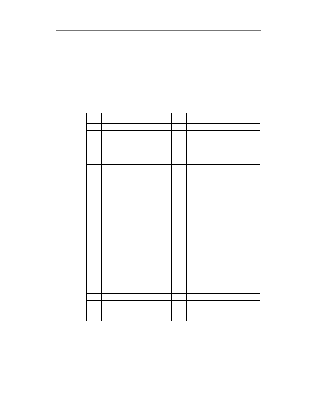
Hardware supported
The table bellow summarizes the hardware supported by
PowerDAQ™ LabVIEW® driver. All the board models in
PowerDAQ I and PowerDAQ II families are supported. Also
included VI’s to support PowerDAQ Thermocouple Rack
(type J and K).
#
Board Model
1 PD-MF-16-1M/12L 30 PD2-MFS-4-1M/12
2 PD-MF-16-1M/12H 31 PD2-MFS-8-1M/12
3 PD-MF-64-1M/12L 32 PD2-MFS-4-400/14
4 PD-MF-64-1M/12H 33 PD2-MFS-8-400/14
5 PD-MF-16-300/12L 34 PD2-MFS-4-800/14
6 PD-MF-16-300/12H 35 PD2-MFS-8-800/14
7 PD-MF-64-300/12L 36 PD2-MFS-4-300/16
8 PD-MF-64-300/12H 37 PD2-MFS-8-300/16
9 PD-MF-16-250/16L 38 PD2-DIO-64
10 PD-MF-16-250/16H 39 PD2-DIO-128
11 PD-MF-64-250/16L 40 PD2-AO-8/16
12 PD-MF-64-250/16H 41 PD2-AO-16/16
13 PD-MF-16-50/16L 42 PD2-AO-32/16
14 PD-MF-16-50/16H 43 PD-TCR-16 (with PDx-MF)
15 PD-MFS-6-1M/12
16 PD2-MF-16-1M/12L
17 PD2-MF-16-1M/12H
18 PD2-MF-64-1M/12L
19 PD2-MF-64-1M/12H
20 PD2-MF-16-400/14L
21 PD2-MF-16-400/14H
22 PD2-MF-64-400/14L
23 PD2-MF-64-400/14H
24 PD2-MF-16-333/16L
25 PD2-MF-16-333/16H
26 PD2-MF-64-333/16L
27 PD2-MF-64-333/16H
28 PD2-MF-16-50/16L
29 PD2-MF-16-50/16H
Chapter 1: Introduction
# Board Model
5
Page 18

Chapter 1: Introduction
PowerDAQ™ Low-level Library
PowerDAQ Low-level library is a set of board-level, analog
input, analog output, digital input and output and countertimers visual instruments most of them were designed to
provide compatibility with National Instruments™ VI’s. The
low-level library provides a direct communication interface
with PowerDAQ™ boards and is a base for all application
development. The library support all advantages of
multithreading environment such as Windows 95/98 or
NT/2000. Each subsystem runs in its separate thread to
provide maximum independence and increase speed of
board operation under LabVIEW®. You can install multiple
PowerDAQ™ boards into the one PC. You are limited to the
number of PCI slots in your PC. For detail description about
each Library VI please refer to the Chapter II.
Generic Examples
Generic Examples provided with PowerDAQ™ driver for the
LabVIEW® includes the examples for:
6
# Analog Input Subsystem Examples
• Single-Channel Acquisition
• Multiple-Channels Acquisition
• FFT
• Thermocouple
• Stream-To-Disk
• Single-Point Acquisition
# Analog Output Examples
• Single-Update Mode
• Buffered Mode
• PowerDAQ™ Analog Output Boards Support
Examples
# Digital Input and Output Examples
• Single-Update Mode
Page 19

Chapter 1: Introduction
• Buffered Mode
• PowerDAQ™ Digital I/O Boards Support Examples
# Counter/Timers Example
• 82C54-based ( MF/MFS series)
• DSP-based 24-bit counter/timers usage (AO/DIO
series)
• Frequency Measurement
The goal of the each generic example is to show specific
feature or features associated with specific task or
subsystem in the simplest way.
For details please see Chapter III
Multi-boards and Multi-subsystem
Examples
Thanks to PowerDAQ™ boards and software design the all
subsystems available on board are ready to access
simultaneously at any time without limitations. You can run
high-speed analog input data acquisition process and work
with counters digital I/O and analog output at the same
time. To make the more complex end-customer application
development easier the multi-board and multi-subsystem
examples are provided.
The multi-boards support examples shows how to use two,
three, four, eight and even ten PowerDAQ™ boards on the
same PC.
The multi-subsystems support examples shows how to
integrate the different subsystems of the PowerDAQ™
together and some advanced techniques for analog
triggering.
All details are described in Chapter III,
Multi-board
section .
Multi-subsystem
and
7
Page 20

Page 21

2
Library
9
Page 22

Library
This chapter is a reference to PowerDAQ™ driver for the
LabVIEW® low-level Library. You can find the description of
each VI included to the Library and explanation how to use
it in a best way.
The Low-level library is a set of basic and more advanced
VI’s which can be used to develop your own dataacquisition-based application using the PowerDAQ boards.
The following sub-division of the Library VI’s can be
defined:
• Board-level
• Analog Input
• Analog Output
• Digital Input
• Digital Output
• Counter-Timers
Chapter 2: Library
10
Note The some VI’s are dedicated to the specific board
type and can not be used with another board type.
In this situation the appropriate error code will be
generated.
Page 23

Chapter 2: Library
Design Notes (Before You Start)
From the LabVIEW® view the PowerDAQ™ board can be
considered as set of subsystems. Generally the following
subsystems can be available on a board (less or more,
depends of the board type):
• Analog Input (PDx-MF(S) models only)
Generally this subsystem has associated with it a certain
number of input channels (channel list), each of which
have an input range. The analog input subsystem can
also have conversion and channel list clock, analog and
digital trigger and input buffer to store the data from
the board.
• Analog Output (PDx-MF(S) and PD2-AO models)
Generally this subsystem has associated with it a certain
number of input channels (channel list), each of which
have an input range (fixed +/-10V for PDx boards). The
analog input subsystem can also have programmable
conversion clock, which allows channels to be updated
at regular intervals.
• Digital Input and Digital Output
This subsystem generally has associated with it a certain
number of digital ports, 8 or 16 bits wide. Most but not
all boards have ports that have dedicated input or
output assigning.
• Counter/Timers
This subsystem generally has associated with it a certain
number of user-accessible on-board counter/timers, 16
or 24 bits wide. They can be programmed either as
inputs (counters) – to measure frequency, pulse
width/period or outputs (timers) to provide variety of
output frequencies.
• Calibration (PDx-MF(S) and PD2-AO models)
11
Page 24
(
q
y
(
)
Initialization
PD xx
Set configuration
for the board
and subsystem
Chapter 2: Library
Note The calibration subsystem of the PowerDAQ™
boards has no access from LabVIEW®. Use the
calibration software provided with PowerDAQ™
SDK to calibrate your board. Please refer to specific
board model manual or datasheet for details about
subsystems available and other information.
Start
uisition
ac
Set acquisition
parameters
(frequency,
etc.) and start
Check for errors
PD Error Ex.VI
Read/Write data
(PD xx Read/Write.VI)
Read/Write/Proce
ss requested
amount of data
to/from the
Release
subs
stem
Stop acquisition,
make subsystem
available for the
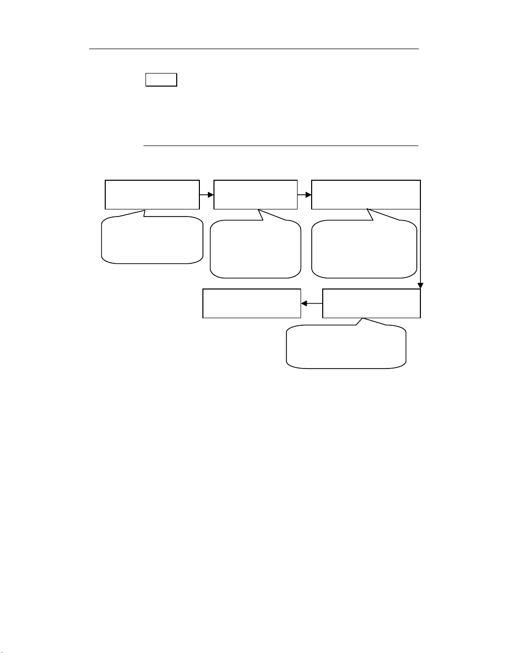
The simplified flow of the LabVIEW®-based data
acquisition application is (see picture above)
• Initialization (generally performed by
call)
• Start the acquisition process (generally performed by
“PD xx Start.VI”
• Read/Write operations for the subsystem selected
(generally performed by
data processing
• Stop the Acquisition (generally performed by
Close.VI”
• Analyze the possible error codes and messages
12
call)
call)
“PD xx Read/Write.VI”
“PD xx Config.VI”
call),
“PD xx
Page 25
Note That second and third items can be exchanged
depends of the subsystem type (input or output).
Some of intermediate level VI can incorporate all
those stages inside and in this situation all
acquisition process can be reduced to the single VI
call (see “PD AI Wave.VI” for example)
Summary
PowerDAQ LabVIEW driver library is a foundation for the
high-level applications. The set of VIs provided in the library
allows you to build more complex VIs using the low-level
ones as basic elements. The Library VIs are updated each
time when we release the new version of PowerDAQ™ SDK.
Normally we include one or two new low-level and
intermediate-level Library VIs into the new release. Thanks to
our “click and replace” technology you can easy convert you
NI-boards oriented sources to the PowerDAQ boards.
Common Inputs and Outputs
Chapter 2: Library
Some inputs and outputs names are used by almost every
Library VI and it would be better to describe them once. The
common inputs and outputs and they description are listed
below:
taskId in
•
taskId Unique hex number of task associated with specified
taskId out
error in
subsystem. Each VI except the "PD xx Config.vi" passes the
value from the
Config.vi" taskId should be used in all down-stream VIs to
provide an access to the board/subsystem initialized in "PD
xx Config.vi" call.
taskId Unique hex number of task associated with specified
subsystem and initially issued by "PD xx Config.vi".
error in error in is a cluster of three elements
- status
- code
- source
taskId in
to the
taskId out
. Issued by "PD xx
13
Page 26
Chapter 2: Library
the error state of upstream VI. The VI executes normally only
if no incoming error exists, otherwise it passes the er
value to
error out
status The status Boolean is either TRUE for an error,
or FALSE for no error or a warning.
code The code input identifies the error or warning.
You can use “PD Error Ex.vi” for an explanation of
non-zero error codes
source The source string describes the origin of the
error or warning. Usually this string contains "No
error" message or name of VI where error occurred.
The “PD Error Ex.VI” explains non-zero error codes.
ror in
•
error out
error out error out is a cluster of three elements
- status
- code
- source
Describes the error state of upstream VI or error code
generated by current VI. The VI executes normally only if no
incoming error exists, otherwise it passes the error in value
to error out.
Status The status Boolean is either TRUE for an error,
or FALSE for no error or a warning.
Code The code input identifies the error or warning.
You can use “PD Error Ex.VI” for an explanation of
non-zero error codes.
source The source string describes the origin of the
error or warning. Usually this string contains "No
error" message or name of VI where error occurred.
Use "PD Error Ex.vi" for an explanation of non-zero
error codes.
14
Page 27
Board-Level and Service VIs
The following list of Library Visual Instruments below can be
defined as board level and service VI.
VI name Description
PD Error Ex.vi Convert error code to string message
PD Get Capabilities.vi Get board capabilities information
PD Shell.vi Call shell function
PD String Array to Int.vi Convert arrays
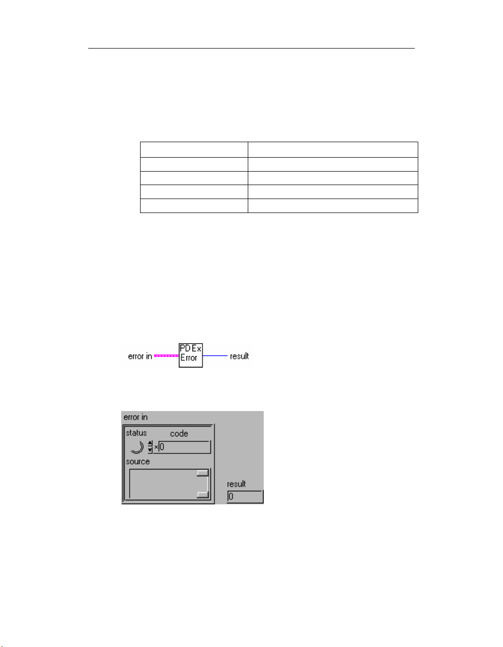
Pd Error Ex.VI
Explains non-zero error codes and shows dialog box with
information about error. In case of zero error code do
nothing.
Connector Panel
Chapter 2: Library
Front Panel
15
Page 28
Chapter 2: Library
Controls and Indicators
error in
see
Common Inputs and Outputs
Result always return 0x0
(reserved for future use)
topic for the description
Block Diagram
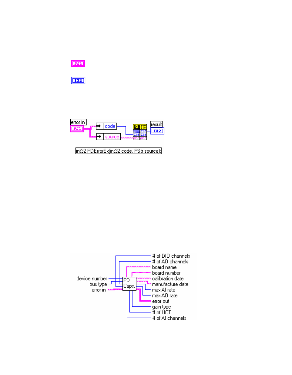
PD Get Capabilities.vi
Board detection VI.
Collects information about specified board at specified bus,
return non- zero error code if board is not found. See “PD
Diagnostic.VI” or “PD AI Single channel realtime display.VI”
for examples.
Connector Panel
16
Page 29
Chapter 2: Library
Controls and Indicators
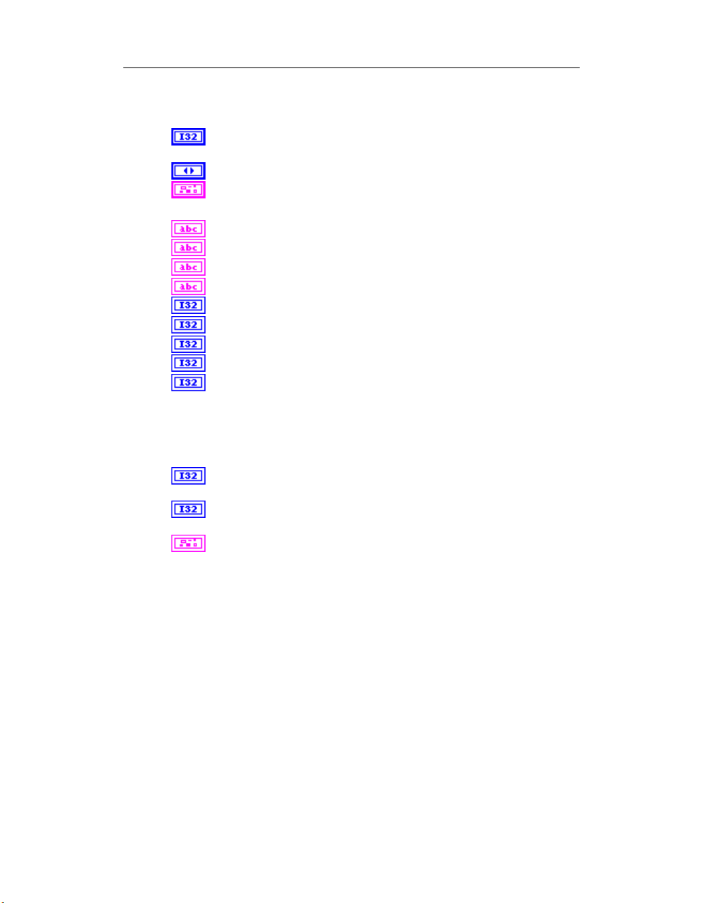
device number Number of device at bus specified (starts from
1)
bus type Bus type where PowerDAQ device installed
error in
see Common Inputs and Outputs topic for the description
board name Type of PowerDAQ board installed
board number Board serial # (from EPROM)
calibration date Board calibration date (from EPROM)
manufacture date Board manufacture date (from EPROM)
# of AI channels Number of analog input channels
# of AO channels Number of analog output channels
# of DIO channels Number of digital input-output channels
# of UCT Number of user counter-timers
gain type Indicates type of board gains
3 means only gain 1 available
2 means 1,2,5,10 gains available
1 means 1,10,100,1000 gains available
0 means 1,2,4,8 gains supported by board
max AI rate Maximum value of analog input rate that
recommended by PowerDAQ technical documentation
max AO rate Maximum value of analog output rate that
recommended by PowerDAQ technical documentation
error out
see Common Inputs and Outputs topic for the description
17
Page 30
Chapter 2: Library
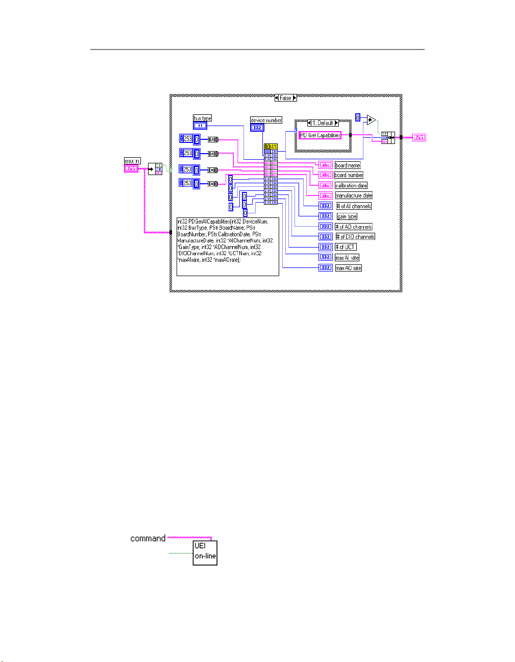
Block Diagram
See also
• PD Get AO Capabilities.VI
• PD Get AI Capabilities.VI
PD Shell.VI
PowerDAQ service VI.
Execute
browser with OMEGA ENGINEERING web-site hot link. See
Windows API
ShellExecuteA
Connector Panel
18
ShellExecuteA
documentation for details about the
function.
function for open default Web-
Page 31
Controls and Indicators
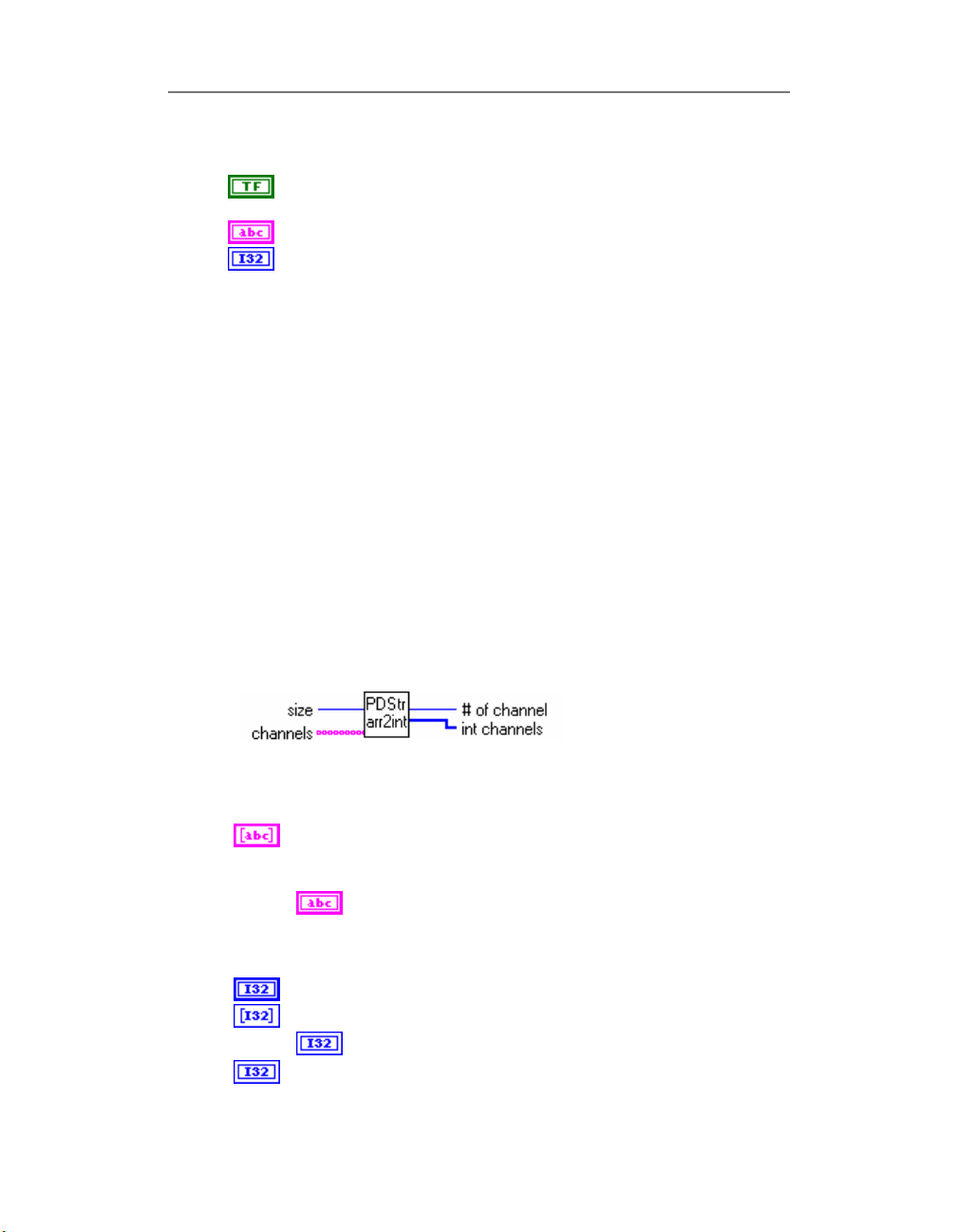
OMEGA ENGINEERING on-line hot link button. When ON(TRUE)
– this VI calls
command command line to be processed by
HInstance Result of
ShellExecuteA
ShellExecuteA
See also
• All PowerDAQ examples with hot-link button.
PD String Array to Int.vi
This PowerDAQ library VI reserved for internal usage only.
Converts string array to array of integers with specified size.
Used in “PD xx Config.VI” to convert LabVIEW channel list in
string array to the PowerDAQ-compatible integer array channel
list.
Connector Panel
function
function call. Void.
Chapter 2: Library
open
command
Controls and Indicators
Channels channels - string array: specifies the set of analog
input channels for a group and task. PowerDAQ limitations: only
digits should be used. See “PD AI Config.VI” for details.
Size size of output array
int channels output channel list in the internal presentation
# of channels output – number of channels used in channel list
channel channels - string array: specifies the set of
analog input channels for a group and task.
PowerDAQ limitations: only digits should be used.
See “PD AI Config.VI” for details.
output channel list in the internal presentation
19
Page 32

Analog Input
The Analog Input part of the PowerDAQ™ MF(S) series
boards is a most advanced and complicated subsystem. The
different type of clocks, triggers, buffer settings associated
with Analog Input subsystem are described in topics below.
For information about clock and buffer settings please refer
to:
• Conversion Clock and Channel List Clock
• Optimizing performance using the buffer settings
The Analog Input VIs in the PowerDAQ™ Library include:
• Configuration Functions
• PD AI Config.VI
• PD AI Fine Tune.VI
• PD AI Start.VI
•
Chapter 2: Library
20
Page 33

Chapter 2: Library
PD AI Stream Init.VI
• PD AI Clear.VI
• PD Get AI Capabilities.VI
• Service Functions
• PD AI Active channels.VI
• PD AI Convert Ranges.VI
• PD AI Data Count.VI
• PD AI Init Arrays.VI
• PD AI Frame Size.VI
• PD AI Thermocouple Control.VI
• PD AI Thermocouple Display.VI
• Analog Input Functions
• PD AI Read Async.VI
• PD AI Read.VI
• PD AI Stream.VI
• Simplified Easy Functions
• PD AI Read One Scan.vi
• PD AI Sample Channel.vi
• PD AI Single Scan.vi
• PD AI Wave.vi
21
Page 34
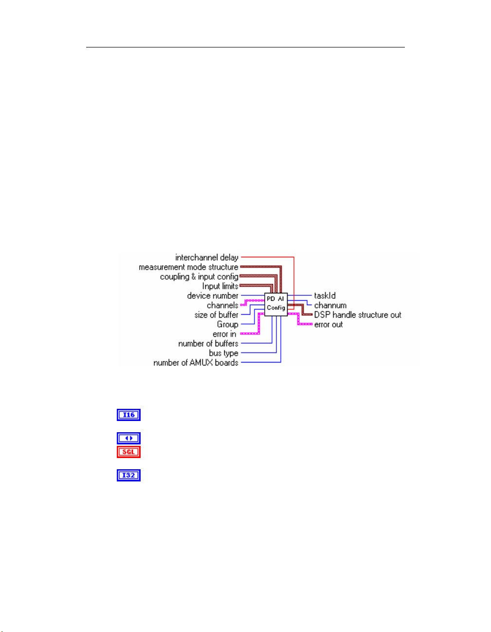
PD AI Config.VI
Basically this VI is used to configure the upper and lower
input limits (and calculate gain for each channel and input
range for whole board automatically), set the channel list,
acquisition buffer size and inter-channel delay for the
board, specified in the
checks the board availability and if specified board available
and Analog Input subsystem exists on the board and not
used by another VI the unique
be used in all sub-sequential VI to provide access to the
same subsystem of the same board. Use “PD AI Clear.VI” to
release the Analog Input subsystem.
Connector Panel
device number
taskId
will be issued. It should
Chapter 2: Library
parameter. This VI
22
Controls and Indicators
device number Number of the device(beginning from 1) at the
bus specified
bus type Bus type where PowerDAQ™ device installed
interchannel delay delay between acquiring each individual
channel in the channel list in seconds ,0 - use default value
size of buffer Set size of buffer for storing the data from the
board – 10000 by default. Buffer allocated and released inside
the PowerDAQ driver. The buffer size is defined in bytes. To
convert bytes into samples, the bytes should be divided by two
(one sample is a one 16-bit word which is equal to the two
bytes). The frame size in LabVIEW is defined in scans. One
scan is a set of the samples – one for each channel in the
channel list. This was done in this way because the most AI xx
functions accept the number of scans as an input parameter, for
Page 35
Chapter 2: Library
the amount of the data requested. To find out the frame size
the following equation should be used:
FrameSize = (((BufferSize / 2 ) / (Number Of The
Frames))/Number Of The Acquired Channels)
The buffer size (in bytes) should be defined using the rule: at
least 1.5 times the Acquisition Rate, for rates between 10K and
200K. And, 2-4 times the Acquisition Rate for high frequencies.
Increasing the buffer size increases the stability and reliability of
the acquisition system at high acquisition speeds.
Channels ([string]) channels: specifies the set of analog input
channels for a group and task.
Example : if only first row of the array used -
‘0,1,2,4’ defines four channels in the channel list,
‘0’ – define empty channel list, ‘1’ define one channel
in the channel list (channel 0),
‘0,’ define one channel in the channel list (channel 0),
‘1,’ define one channel in the channel list (channel 1).
Channel input – string array channels: specifies the set
Input limits input limits is an array of clusters. You can use it
for tune board gain and input type. We use this input for
capability with National Instruments™ “G” sources.
Specify low and high level of input signals (in Volts) or leave
empty array, which means the input limits keep their default
settings.
The default value is +/-10V for all PD(2)-MF(S) boards.
of analog input channels for a group and task.
PowerDAQ limitations : only digital numbers of channels,
',',';' should be used in channel list definition as a channel
delimiters.
If more then one row used, they are OR-ed
together and following rule is used – ‘0’ in row n means
that channel n is not present in the channel list, ‘1’
means that channel n present in the channel list, string
separated by commas will be processed using the rule
described above for the first row.
You can set gains per channel directly in “PD AI Fine
Tune.VI“
input - cluster of input limits: an array of clusters, of
which each array element specifies the range limits for
the channel(s) in the corresponding element of the
23
Page 36
Chapter 2: Library
channels array. If there are fewer elements in this array
than the number of channels, the VI uses the default
values for the rest of the channels. Each cluster contains
the following parameters:
high limit – single : specifies the maximum scaled
data in Volts (10.0 - default)
low limit – single : specifies the minimum scaled data
in Volts (-10.0 - default)
High limit (10.0) high limit - single : specifies
the maximum scaled data in Volts (10.0 – default)
Low limit (-10.0) low limit - single : specifies
the minimum scaled data in Volts (-10.0 - default)
coupling & input config coupling & input config is an
array of clusters. PowerDAQ™ LabVIEW® driver use only
type of inputs (differential/single-ended) and, if both of
them specified differential have high priority and used to
set board configuration
input – cluster coupling & input config:
an array of clusters, of which each array element
specifies the coupling and input configuration for
the channel(s) in the corresponding element of the
channels array.
PowerDAQ™ LabVIEW® driver use only type of
inputs (differential/single-ended) and, if both of
them specified differential have high priority and
will be used to set board configuration
The default input is an empty array, which means
the parameters do not change from their default
settings. Each cluster contains the following
parameters:
coupling:
This input is not used by PowerDAQ™
boards and ignored (both AC and DC modes are
supported and boards have a perfect specs in full
24
Page 37
Chapter 2: Library
bandwidth)
input config:
0: Do not change the input config setting.
1: Differential.
2: Not used (reserved)
3: Non-referenced single-ended
Coupling (no change:0) coupling.
This input is not used by PowerDAQ™ boards and ignored
(both AC and DC modes are supported and boards have a
perfect specs in full bandwidth)
Input config (no change:0) input config.
0: Do not change the input config setting.
1: Differential.
2: Not used (reserved)
3: Non-referenced single-ended
This value used for all analog input channels, but if you
specify it for more than one channel the differential
mode have a highest priority
error in
see Common Inputs and Outputs topic for the
description
number of buffers This input is not used by
PowerDAQ™ boards and ignored
Group This input is not used with PowerDAQ boards
because only one upper level VI can use Analog Input
subsystem of board at time (see
Programmer Guide
number of AMUX boards This input is not used by
PowerDAQ™ boards and ignored
measurement mode structure This input is not used by
PowerDAQ™ boards and ignored
measurement mode This input is not used by
PowerDAQ™ boards and ignored
reserved
)
PowerDAQ™ API
25
Page 38
Chapter 2: Library
Allocation mode (no change:0) PowerDAQ driver
allocates the memory buffer automatically but if 999
specified as input value for this input buffer will not be
allocated. It is useful for single scan operations.
taskId Unique hex number of task associated with
specified subsystem. Each VI except the "PD xx Config.vi"
passes the value from the
Issued by "PD xx Config.vi" taskId should be used in all
down-stream VIs to provide an access to the
board/subsystem initialized in "PD xx Config.vi" call.
channum Total number of channels in channel list. Use
“PD AI Active Channels.VI” to receive this number via
taskId
at any time after “PD AI Config.VI” has been called.
error out
see Common Inputs and Outputs topic for the
description
DSP handle structure out This input is not used by
PowerDAQ™ boards and ignored
size This input is not used by PowerDAQ™ boards
and ignored
DSP memory handle This input is not used by
PowerDAQ™ boards and ignored
taskId in
to the
taskId out
.
26
Page 39
Chapter 2: Library
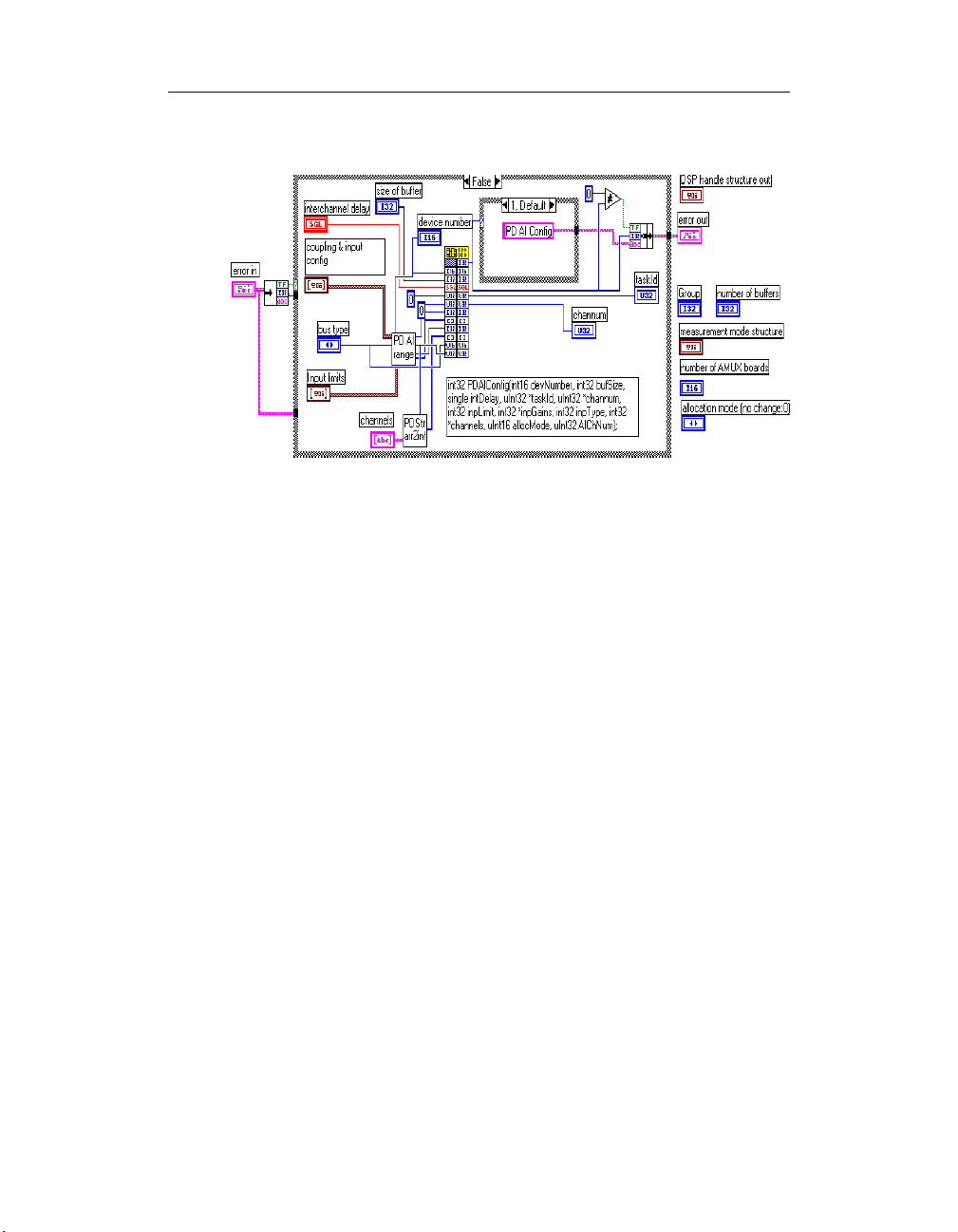
Block Diagram
See also
• PD AI Clear.VI
• PD AI Start.VI
• Analog Input Examples
27
Page 40

PD AI Clear.VI
This VI stops any analog input acquisition process, frees
resources, clear buffers and returns zero
have called this VI you can reuse analog input subsystem for
another task in LabVIEW.
Connector Panel
Controls and Indicators
error in
see Common Inputs and Outputs topic for the
description
task Id in Unique hex number of task to be cleared
see Common Inputs and Outputs topic for the
description
task Id out output - always 0
error out
see Common Inputs and Outputs topic for the
description
Chapter 2: Library
taskId
. After you
28
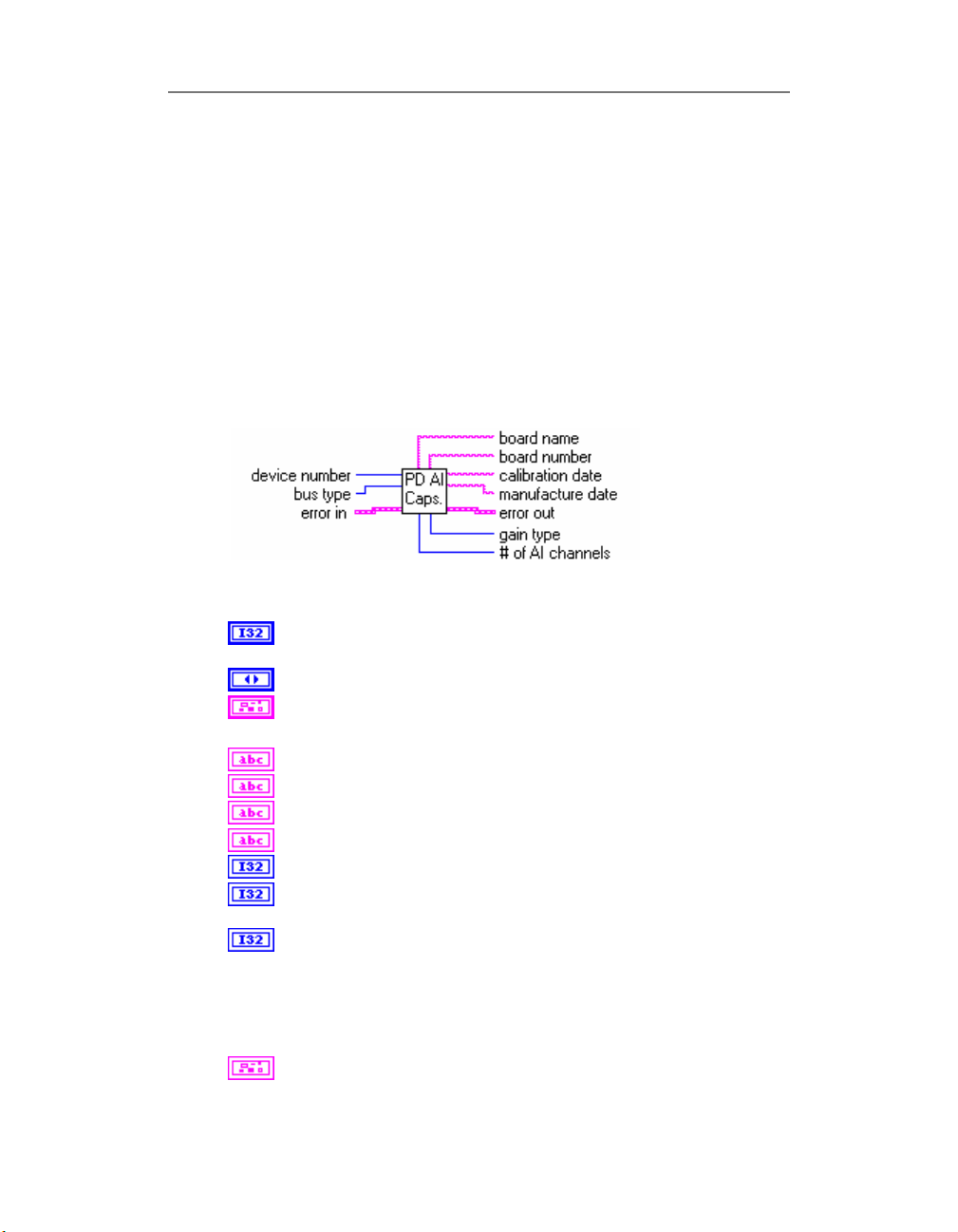
Block Diagram
See also
• PD AI Config.VI
Page 41
• PD AI Start.VI
• Analog Input Examples
PD Get AI Capabilities.VI
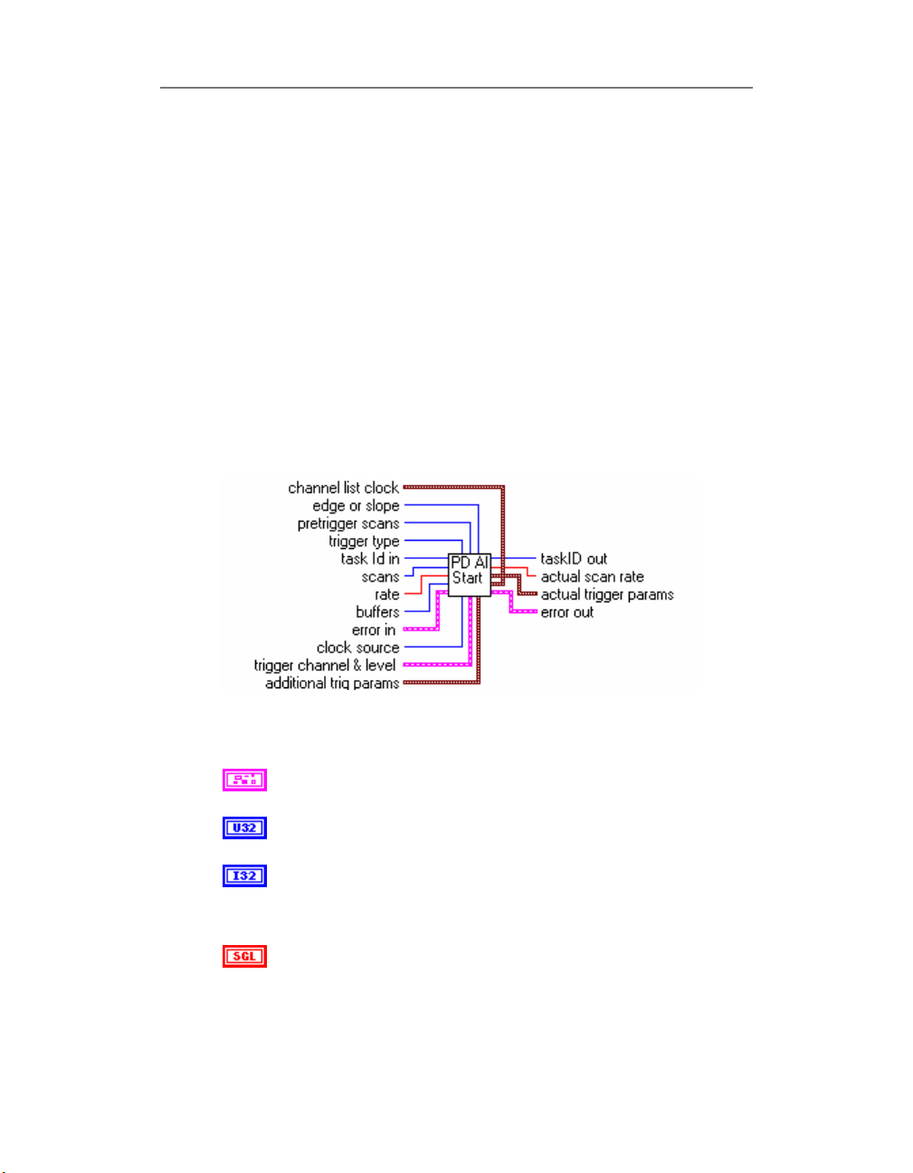
Collects information about analog input subsystem of
specified board at specified bus , return non zero error code
(from PD Get Capabilities) if board is not found
Connector Panel
Controls and Indicators
Chapter 2: Library
device number Number of device at bus specified (beginning
from 1)
bus type Bus type where PowerDAQ device installed
error in
see Common Inputs and Outputs topic for the description
board name Type of PowerDAQ board installed
board number Board serial # (from EEPROM)
calibration date Board calibration date (from EEPROM)
manufacture date Board manufacture date (from EEPROM)
# of AI channels Number of analog input channels
max AI rate Maximum value of analog input rate that
recommended by PowerDAQ technical documentation
gain type Indicates type of board gains
3 means only gain 1 available
2 means 1,2,5,10 gains available
1 means 1,10,100,1000 gains available
0 means 1,2,4,8 gains supported by board
error out
29
Page 42

Chapter 2: Library
see Common Inputs and Outputs topic for the description
See also
• “
30
Page 43
PD AO Config.VI”
• “PD Get Capabilities.VI”
PD AI Start.VI
This VI configures the rate, channel list and conversion clock
source and triggering conditions (digital or analog), sets
total number of scans to acquire or continuos mode and
starts analog input subsystem of PowerDAQ board which
specified via taskId.
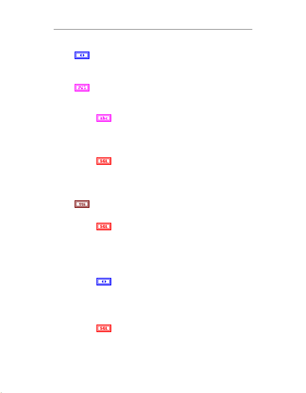
Connector Panel
Chapter 2: Library
Controls and Indicators
error in
see Common Inputs and Outputs topic for the description
task Id in
see Common Inputs and Outputs topic for the description
scans Total number of scans to be acquired. After the board
acquire requested amount of scans acquisition will be stopped
automatically. Specify zero value or leave unconnected for
continuous acquisition.
rate Frequency of A/D conversion clock (CV Clock). If you
acquiring more than 1 channel actual frequency for each channel
should be calculated as
31
Page 44

Chapter 2: Library
(Scan rate)/(Number of active channels)
Note
PowerDAQ board to clock acquisition – channel list clock and A/D
conversion clock. Please refer to
List Clock
buffers now ignored by PowerDAQ
trigger type trigger type
0 – no triggering (default input).
1 – analog trigger (default setting) - one of the analog
channels in channel list used for triggering.
2 – digital trigger A - for PowerDAQ boards - digital trigger on
rising edge.
3 – digital trigger A and B - for PowerDAQ boards - digital
trigger on falling edge.
4 – external high-speed hardware trigger (see usage notes
below).
Note
channel list could be specified in trigger channel control (0 default channel). For trigger type 2 and 3 any numbers of digital
channels could be specified.
----------------------------------------------For the trigger type 4 the following values in the first entry in the
channel list could be used:
0 – do not use external trigger line to start acquisition.
1 – use rising edge of the external trigger line to start
acquisition.
2 – use falling edge of the external trigger line to start
acquisition.
3 – reserved
For the trigger type 4 the follows values in the second entry in the
channel list could be used:
0 – do not use external trigger line to stop acquisition.
1 – use rising edge of the external trigger line to stop
acquisition.
2 – use falling edge of the external trigger line to stop
acquisition.
3 – reserved
-----------------------------------------------
pretrigger scans The pre-trigger data size, specified in scans. The
pretrigger data size is limited by Frame Size. See “PD AI Frame
There are two different type of clocks available on
Conversion Clock and Channel
section in Advanced Topics for details.
For trigger type 1 one analog channel that exists in
32
Page 45
Chapter 2: Library
Size.VI” for details.
edge or slope edge or slope.
0 - Do not change the default setting (default input).
1 - rising.
2 - falling.
trigger channel & level trigger channel(s) and level
Analog level and analog or digital channel(s) for triggering should
be specified via this cluster.
trigger channel Specify trigger channel number(s)
additional trig params advanced trigger parameters for best
triggering
For trigger type 1 analog channel existing in channel list
could be specified in trigger channel control (0 - default
channel). For trigger type 2 and 3 any numbers of digital
channels could be specified.
level
Level (measured in Volts) which analog source must cross
for a trigger to occur. You must also specify whether level
must be crossed on a leading or trailing slope with the
edge or slope input. The default input for level is 0.0.
Hysteresis –
The hysteresis of the signal in Volts. The default input and
setting are 0.0. The hysteresis value refers to a limit above
or below the actual trigger level, which will need to be
surpassed before it is considered to be a valid trigger. This
compensates for the possibility of a noise spike causing an
accidental trigger condition to be detected
coupling coupling of signal
0: Do not change the trigger coupling setting (default
input).
1: DC.
2: AC (reserved)
delay pre-triggering delay in seconds. The default input
and setting are 0.0 seconds.
33
Page 46
Chapter 2: Library
skip count skip count is the number of triggers the VI skips
clock source A/D clock source (CV Clock Source)
0 : software
1 : internal(default)
2 : external raising
3 : external falling
4 : continuos
rate (5000..MaximumFrequency] or specify timeout when PD AI
Read called
channel list clock There are two main clocking signals for analog
input of PowerDAQ boards - channel list start clock (CL Clock)
and A/D (CV Clock) acquisition clock. Acquisition clock controls
each acquisition and channel list start clock controls the start of
each scan (channel list) acquiring... Please refer to
Clock and Channel List Clock
details.
before triggering the acquisition.
-1 - no change the skip count setting
0 - default - no skip any triggers.
time limit time limit set the amount of time for PowerDAQ
LabVIEW driver waits for the trigger to occur.
-1.0 -no change the time limit setting
0 - (default) no waiting.
The "time limit" control sets the windowing size to be
analyzed in the data stream before control is returned to
the other sections of the VI. If a trigger is not detected
during this window, the trigger "Timeout" situation will
flash and control will return to the other subsystems
before returning to analyze another window of data. The
minimum length of the trigger signal is the number of
channels divided by the Scan rate. (If you don't acquire
the trigger, you can't trigger on it.)
Note
: For an external clock you should provide expected scan
Conversion
section in Advanced Topics for
clock source channel list (CL) clock source
0 : software
1 : internal(default)
2 : external raising
3 : external falling
4 : continuos
34
Page 47
Chapter 2: Library
Note
scan rate (5000..MaximumFrequency] or specify timeout
when PD AI Read called
rate Channel list clock rate. By default channel list start
error out
see Common Inputs and Outputs topic for the description
taskID out
see Common Inputs and Outputs topic for the description
actual scan rate Actual acquisition rate, CV clock based (returned
from driver). If you acquiring more than 1 channel actual
frequency for each channel could be calculated as
(Scan rate)/(Number of active channels)
actual trigger params actual trigger params may differ slightly
from the requested trigger inputs, depending on the hardware
capabilities.
continuously but if other specified this value used for
channel list frequency, calculations are following : rate <=
(board rate) / (number of channels). Using high A/D
frequency and low channel list frequency you can receive a
"Virtual Sample and Hold effect".
level actual level of the analog trigger used.
hysteresis actual hysteresis is the hysteresis the VI used.
delay actual delay is the delay the VI used.
: For an external clock you should provide expected
35
Page 48
Chapter 2: Library
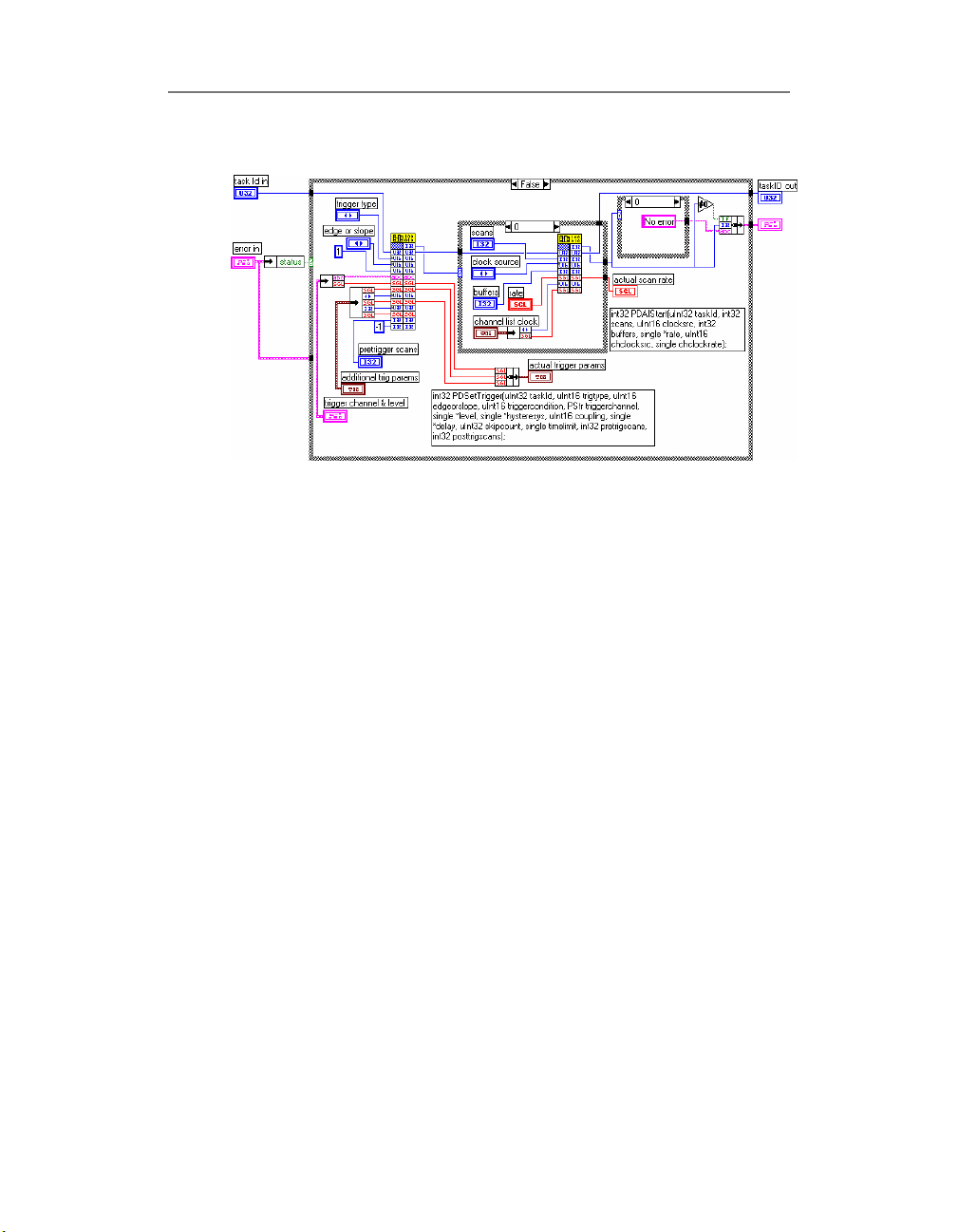
Block Diagram
See also
• PD AI Clear.VI
• PD AI Config.VI
• Analog Input Examples
PD AI Fine Tune.vi
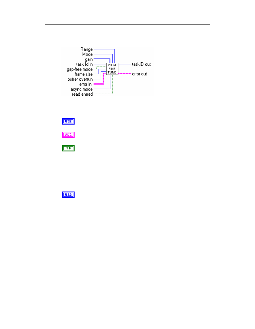
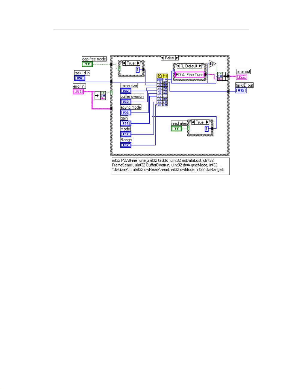
The “PD AI Fine Tune.VI” is used to set advanced
PowerDAQ board analog input settings that are not available
via “PD AI Config.VI” because of compatibility. The following
parameters can be changed using this VI :
• Buffer/FIFO overrun mode
• Analog Input Range and Mode (Single-
Ended/Differential)
• Gains (per channel)
This VI should be called after “PD AI Config.VI” but before
“PD AI [Async] Read.VI” or “PD AI Stream.VI”.
36
Page 49
Chapter 2: Library
Connector Panel
Controls and Indicators
task Id in
see Common Inputs and Outputs topic for the description
error in
see Common Inputs and Outputs topic for the description
gap-free mode
This parameter is a Boolean and dedicated to the on-
board A/D FIFO buffer. When set to ON (TRUE) any on-board
FIFO overrun will cause an error and stop acquisition. If this
parameter set to OFF (FALSE) the on-board FIFO overrun
situation will restart acquisition without any error messages.
Set this parameter to OFF for most tasks except the
gap-free critical stream to disk applications.
frame size Set user-defined number of scans in frame.
(0 - use default Frame Size)
In general the PowerDAQ™ buffer is a driver-allocated
space in the host PC memory which is used to store the
acquired data. The buffer is divided by some number of logical
segments (16 by default). The application will be notified that
new data is available only after the next frame is done. The
buffer size is defined in bytes. To convert bytes into samples,
the bytes should be divided by two (one sample is a one 16-bit
word which is equal to the two bytes). The frame size in
LabVIEW is defined in scans. One scan is a set of the samples
– one for each channel in the channel list. This was done in this
way because the most “PD AI xx” functions accept the number
of scans as an input parameter, for the amount of the data
requested. To find out the frame size the following equation
37
Page 50
Chapter 2: Library
should be used:
FrameSize = (((BufferSize / 2 ) / (Number Of The
Frames))/Number Of The Acquired Channels)
Note
Config.VI” call and before “PD AI Start.VI” call.
The number of frames in the buffer is sixteen by
default, the current Frame Size can be determined using the
“PD AI Frame Size.VI”
The frame size should not be less than One-Half of the onboard FIFO size (in scans). This is not a required but
recommended because of the internals of transferring
mechanism.
The Number Of Frames in a buffer should not be less
than 4, when the high response is a requirement the frame size
should be minimized and amount of frames in the buffer
increased.
buffer overrun Buffer overrun mode
Integer parameter with four possible values. This parameter is
dedicated to PowerDAQ LabVIEW driver buffer in host PC
memory space and can be used depends of the application
requirements.
0 - the buffer overrun is not allowed any buffer overrun will
cause an error and stops acquisition.
1 - the buffer overrun is allowed, but driver use buffer in
recycle mode, when newest data can override the old one even
if this data is not read yet. No errors will be generated in this
situation.
2 - the buffer overrun is allowed, any buffer overrun will restart
acquisition.
3 - buffer will be acquired only once and acquisition will be
stopped.
acync mode Operation mode (synchronous/asynchronous)
0 - do not change (default)
1 - asynchronous operation (“PD AI Read Async.VI” should be
used)
2 - synchronous operation (“PD AI Read.VI” should be used)
: This parameter should be changed only after “PD AI
38
Page 51
Chapter 2: Library
When synchronous mode used each “PD AI Read[Stream].VI”
call will wait until board will collect required amount of the data
or user-specified timeout will be expired and only after that
control will be returned to the LabVIEW®. This means that VI
execution will frees for the time necessary to collect the data.
If asynchronous mode used the control will be returned to the
LabVIEW immediately from “PD AI Read Async.VI” call
regardless of data availability. If there are not enough data
available the specific error code will be returned.
gain input – array that set gain level for each AI channel.
read ahead This parameter is a Boolean and responsible for
behavior of how the “PD AI xx Read[Stream].VI” retrieving the
data from the PowerDAQ driver buffer. When set to ON
(TRUE) “PD AI Read[Stream].VI” will check how many data is
inside the buffer not read yet. (To see this inside the LabVIEW
the “PD AI Data Count.VI” provided. If more than ½ of the
acquisition buffer is already contains the data each call of “PD
AI Read[Stream]. VI” will try to retrieve two frames at time
gain input - [i32] array used to set desired gains for the
analog inputs directly and override the settings made in
the "PD AI Config.VI". Each array item represents one
channel in the channel list. There are following options
available to select from:
-1 (default input) do not change the gain
0 set the gain 1
1 set the gain 2
2 set the gain 4
3 set the gain 8
4 set the gain 10 for the boards with gains
1/10/100/1000
5 set the gain 100
6 set the gain 1000
7 set the gain 5
8 set the gain 10 for the boards with gains
1/2/5/10
Note
1/10/100/1000, 1/2/5/10 or just 1, depends of the
board installed, to determine the gain type use "PD Get
AI Capabilities.VI". For this particular input it is a user
responsibility to use the correct gain code.
The gains are available only in sets of 1/2/4/8,
39
Page 52
Chapter 2: Library
instead of one. If it OFF (FALSE) only one frame a time will be
requested from the PowerDAQ driver.
Mode Analog Input mode
Allow to set analog input mode directly and override the
settings made in the "PD AI Config.VI".
0 - do not change
1- single-ended
2 – differential
Range Analog Input Range
Allow to set analog input mode directly and override the
settings made in the "PD AI Config.VI".
0 - do not change
1 - 0..5 V
2 - +/-5 V
3 - 0..10 V
4 - +/-10 V
taskID out
see Common Inputs and Outputs topic for the description
error out
see Common Inputs and Outputs topic for the description
40
Page 53
Chapter 2: Library
Block Diagram
See also
• PD AI Clear.VI
• PD AI Config.VI
• PD AI Start.VI
• Optimizing performance using the buffer settings
• Analog Input Examples
41
Page 54
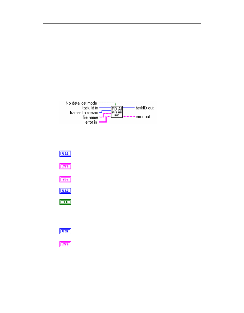
PD AI Stream Init.vi
Prepares analog input subsystem of the PowerDAQ board
for the stream-to-disk operation. Used with “PD AI
Stream.VI”
Connector Panel
Chapter 2: Library
Controls and Indicators
task Id in
see Common Inputs and Outputs topic for the description
error in
see Common Inputs and Outputs topic for the description
file name File name for accept acquiring data. Catalog must be
exist.
frames to stream Total number of the frames. Specify zero for
continuos streaming or any number.
No data lost mode Allows to select one of two acquisition
modes:
- OFF: with small possibility of data loss but non-stop
acquisition.
- ON: set PowerDAQ LabVIEW driver to "no data lost" mode.
task Id out
see Common Inputs and Outputs topic for the description
error out
see Common Inputs and Outputs topic for the description
42
Page 55
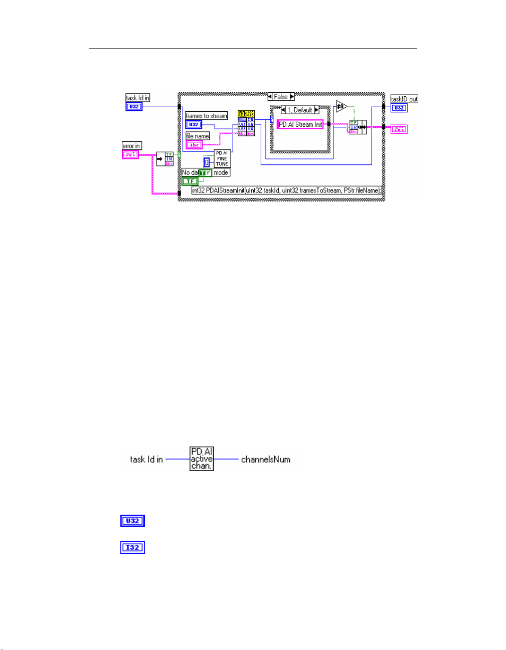
Chapter 2: Library
Block Diagram
See also
• PD AI Stream.VI
• PD AI Stream To Disk.VI (Example)
• Optimizing performance using the buffer settings
• Multi-board streaming Examples
PD AI Active channels.vi
PowerDAQ LabVIEW advanced VI - returns the number of
active channels in the channel list for specified taskId. In
case of zero or invalid taskId returns 0.
Connector Panel
Controls and Indicators
task Id in
see Common Inputs and Outputs topic for the description
channelsNum output - total number of analog input channels
used for specified taskId.
This is an advanced VI and be careful with passed parameter -
43
Page 56
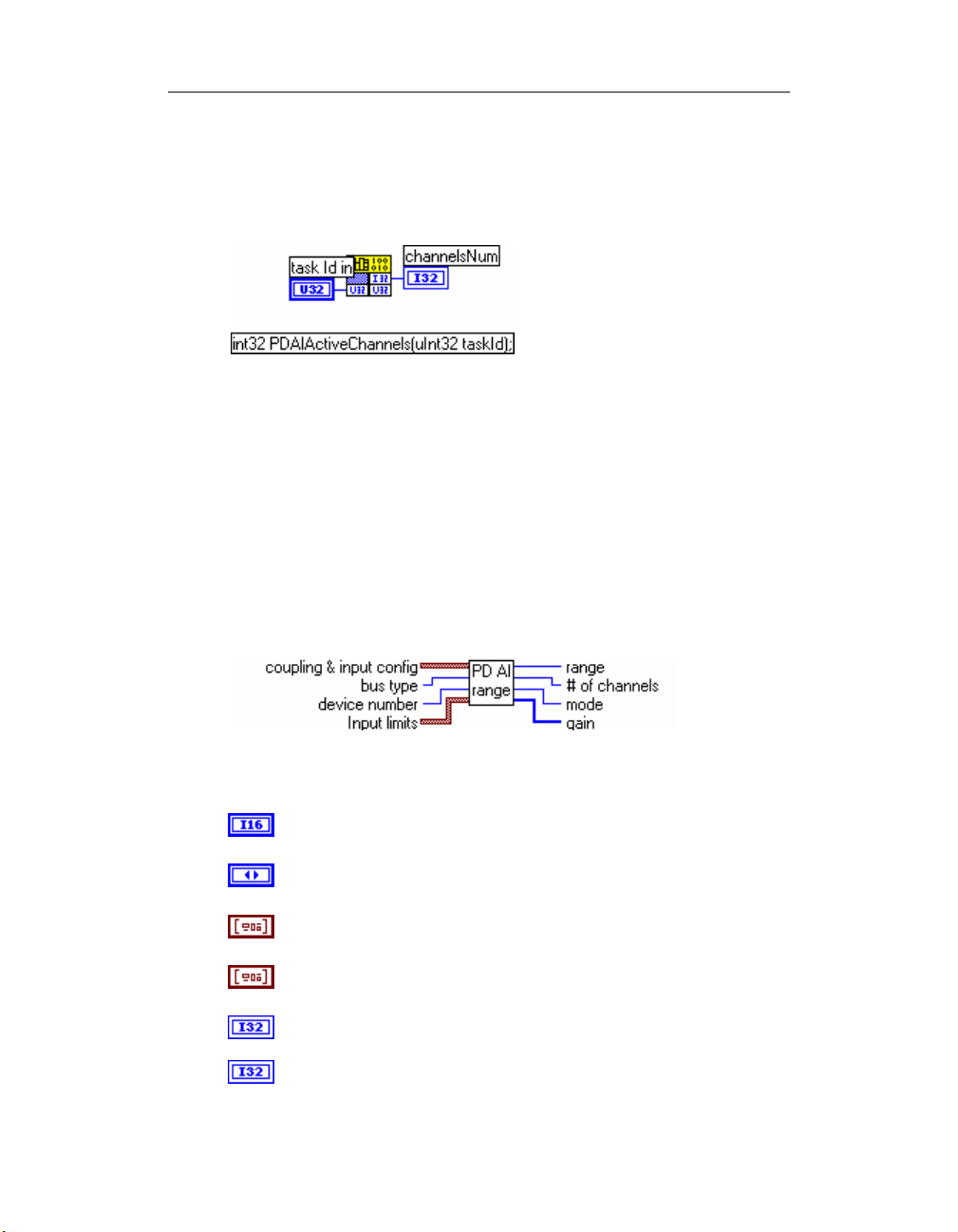
if any error detected, it returns zero as a result.
Block Diagram
PD AI Convert Ranges.vi
This VI converts input limits/ranges for analog input channels
that are specified in the standard LabVIEW format into
PowerDAQ compatible values. This VI is dedicated to the
internal usage and should not be used in user applications.
Chapter 2: Library
44
Connector Panel
Controls and Indicators
device number
see PD AI Config.VI topic for the description
bus type
see PD AI Config.VI topic for the description
Input limits
see PD AI Config.VI topic for the description
coupling & input config
see PD AI Config.VI topic for the description
range analog input range code formatted to the internal
PowerDAQ presentation
mode analog input mode code formatted to the internal
Page 57
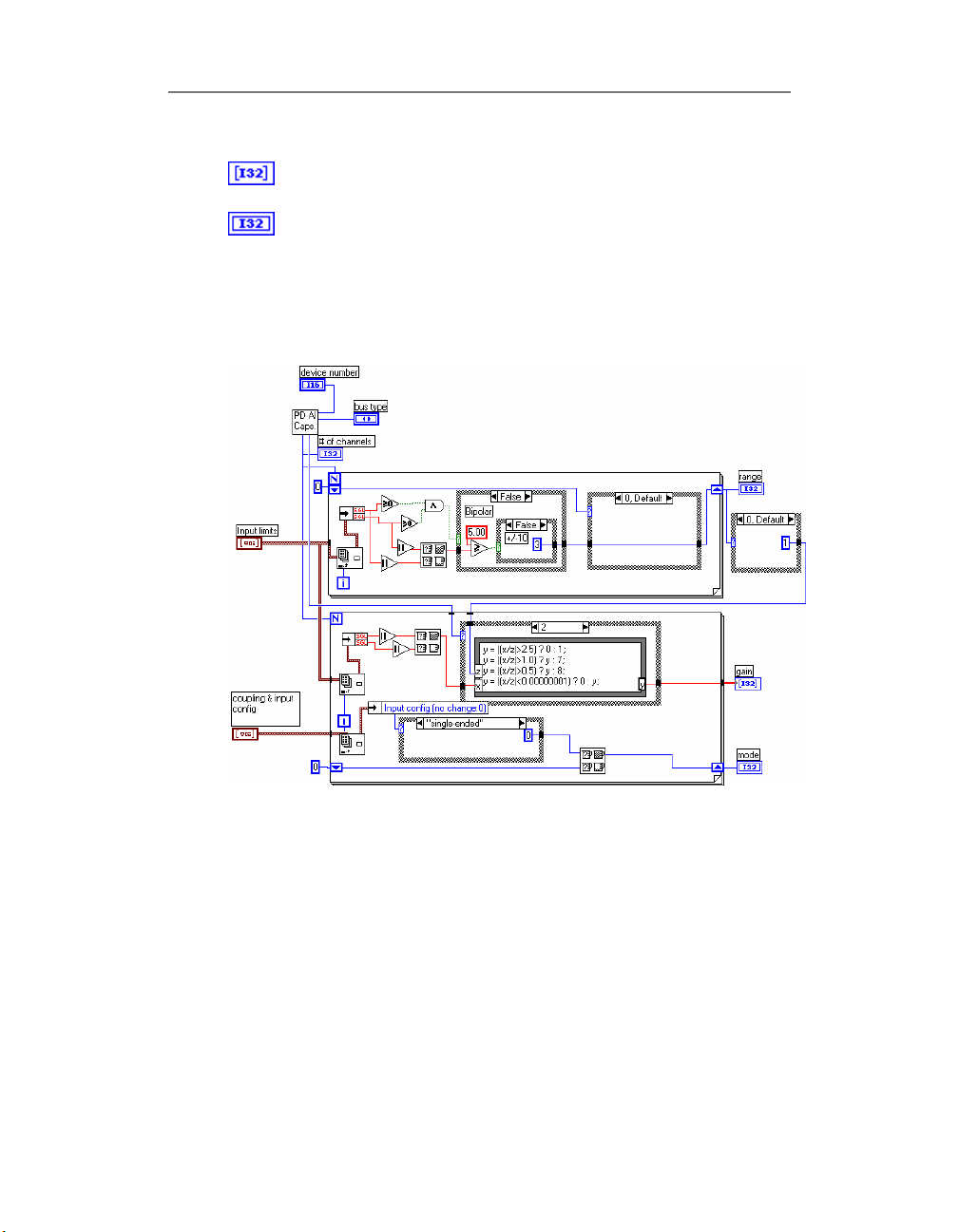
Chapter 2: Library
PowerDAQ presentation
gain output - array that set gain level for each AI channel.
# of channels output - total number of analog input channels
on specified PowerDAQ board
Block Diagram
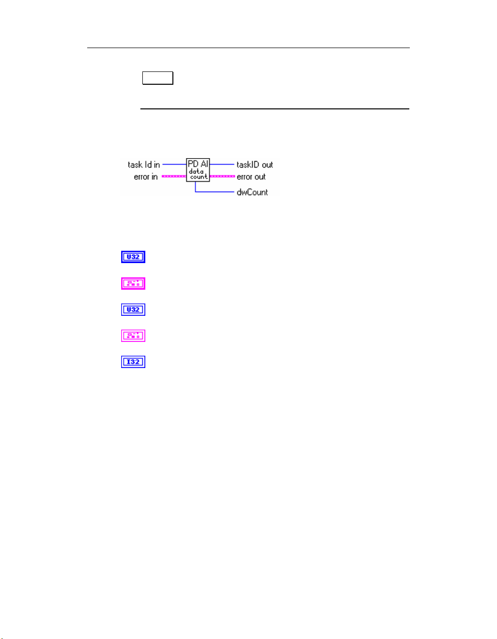
PD AI Data Count.VI
PD AI Data Count is an Advanced Library VI that can be
used to determine the stability of an acquisition system.
To keep the acquisition system healthy the maximum value
of the result of this function call should be less then ½ of
the acquisition buffer size measured in samples (one sample
is equal to two bytes).
45
Page 58
Chapter 2: Library
Note Another parameter which could be helpful for
performance monitoring tasks is the Kernel time
usage (see your WIN32 API documentation).
Connector Panel
Controls and Indicators
task Id in
see Common Inputs and Outputs topic for the description
error in
see Common Inputs and Outputs topic for the description
taskID out
see Common Inputs and Outputs topic for the description
error out
see Common Inputs and Outputs topic for the description
dwCount uint32 - amount of data in the acquisition buffer (in
samples) that has not been read into LabVIEW. This value is a
different than
See “PD AI Read.VI” fo details.
backlog
parameter from “PD AI Read.VI” call.
46
Page 59
Chapter 2: Library
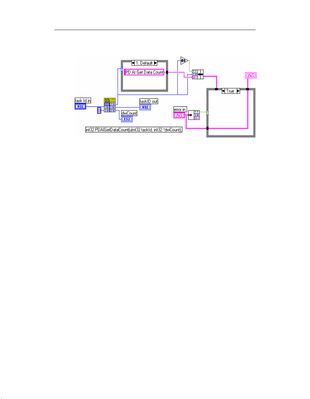
Block Diagram
See also
• PD AI Acquire Eight Channels.VI (Example)
• Optimizing performance using the buffer settings
PD AI Init Arrays.vi
Used to pre-allocate LabVIEW arrays for “PD AI Async
Read.VI” call. This VI is dedicated to the internal usage and
should not be used in user applications.
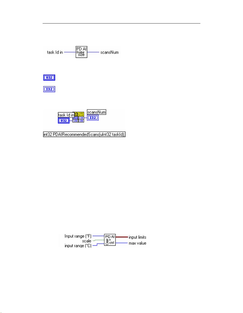
PD AI Frame Size.VI
Returns the current analog input buffer frame size measured
in scans. This or even to this number of scans requested
could be passed into “PD AI Read.VI” to acquire the data
without any loss. In case of zero or invalid
See Input buffers. General Information topic for the
detailed description about PowerDAQ buffering mechanism.
taskId
returns 0.
47
Page 60
Connector Panel
Chapter 2: Library
Controls and Indicators
task Id in
Block Diagram
see Common Inputs and Outputs topic for the description
scansNum output - recommended number of data (in scans).
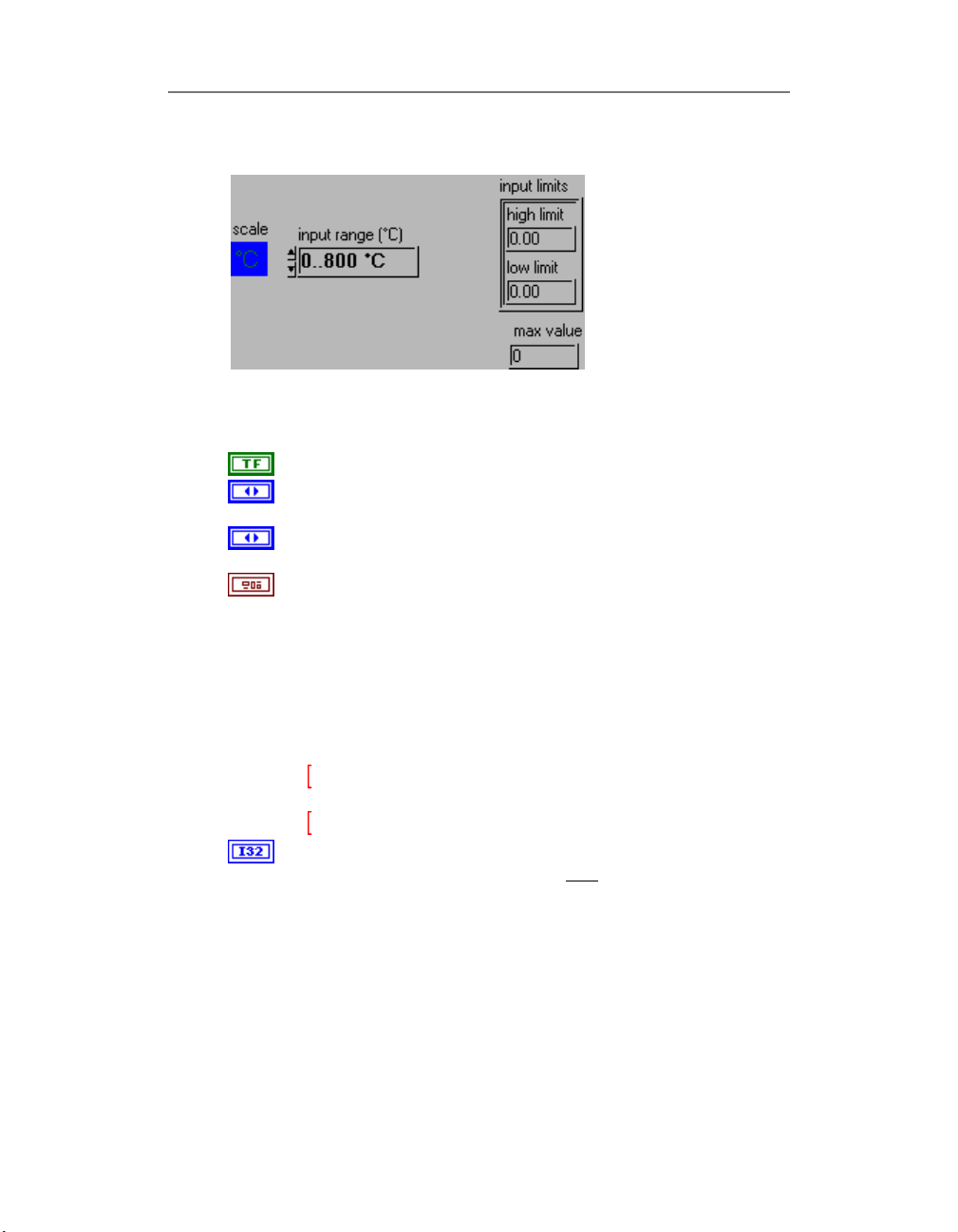
PD AI Thermocouple Control.VI
This VI used to convert visual controls (temperature scale
and input range for selected scale) to cluster of input limits
that should be connected to the Build Array LabVIEW VI
which should be connected to the “PD AI Config.VI”. See
“PD AI 16 Channels Thermocouple Rack.VI” for example. For
temperature data use “PD AI Thermocouple Display.VI”.
48
Connector Panel
Page 61
Chapter 2: Library
Front Panel
Controls and Indicators
scale Measurement mode switch : °F /°C
input range (°C) Choosing the correct input range increases
precision of temperature measurement
Input range (°F) Choosing the correct input range increases
precision of temperature measurement
input limits – output.
This cluster calculated depends of the input range selected and
board type installed.
Input limits is a cluster of two elements
High limit (Volts)
Low limit (Volts. )
Low limit always is zero and high limit is calculated inside the
VI.
high limit high limit calculated depends of the input
temperature range selected
low limit low limit is always zero
max value output - maximum value of temperature in scale
selected. Should be connected to
Thermocouple Display.VI.”
max
value input of “PD AI
49
Page 62
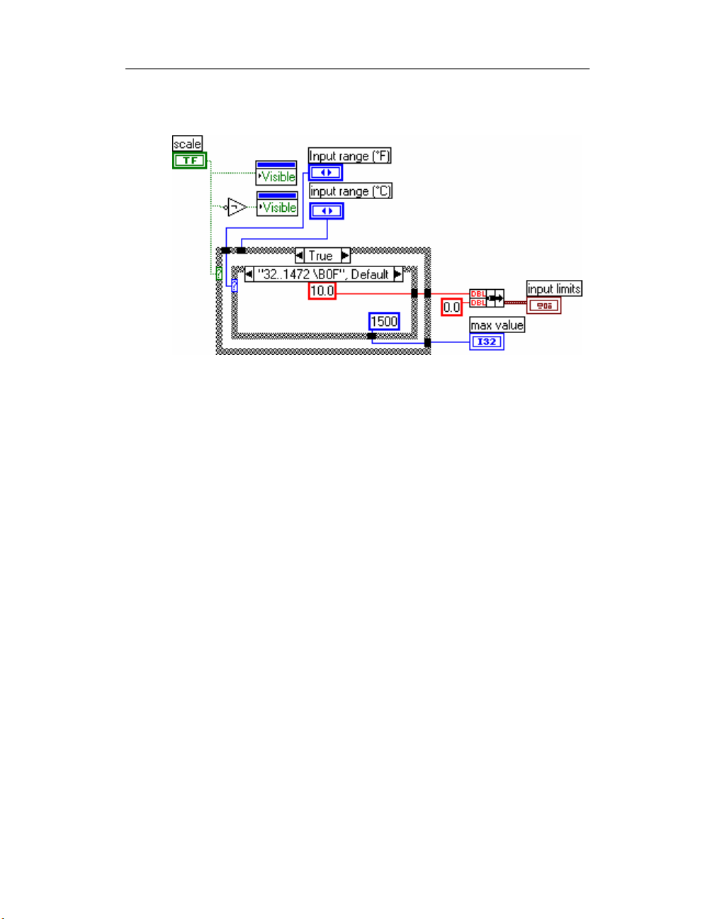
Chapter 2: Library
Block Diagram
See also
• “PD AI 16 Channels Thermocouple Rack.VI” (Example)
“
• PD AI Thermocouple Display.VI”
PD AI Thermocouple Display.VI
This VI displays data (temperature or Volts) on digital
indicator. For temperature it converts voltage into the
temperature for scale (F/C) and thermocouple type (J or K)
selected. -9999.00 means 'data out of range'. See “PD AI 16
channels thermocouple rack.VI” for example. For tune
channel which thermocouple connected use “PD AI
Thermocouple Control.VI”
50
Page 63
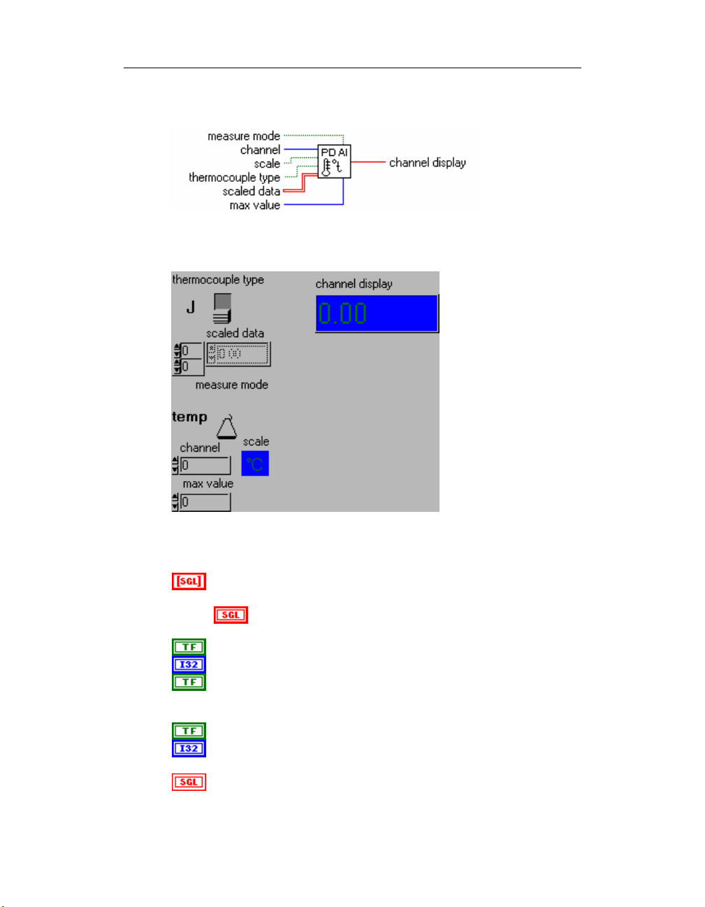
Chapter 2: Library
Connector Panel
Front Panel
Controls and Indicators
scaled data Scaled data (in Volts) from the PowerDAQ
board driver
Scaled data (in Volts) from the PowerDAQ board
driver
measure mode Temperature/voltage display mode switch
channel Channel number for display
thermocouple type Thermocouple type switch. There is two
type of thermocouple available with PowerDAQ board - J
and K.
scale Measurement mode switch : °F /°C
max value Input - maximum value of temperature in scale
selected. If overloaded passes 9999.00 to output
channel display Displays the data from selected channel in
51
Page 64
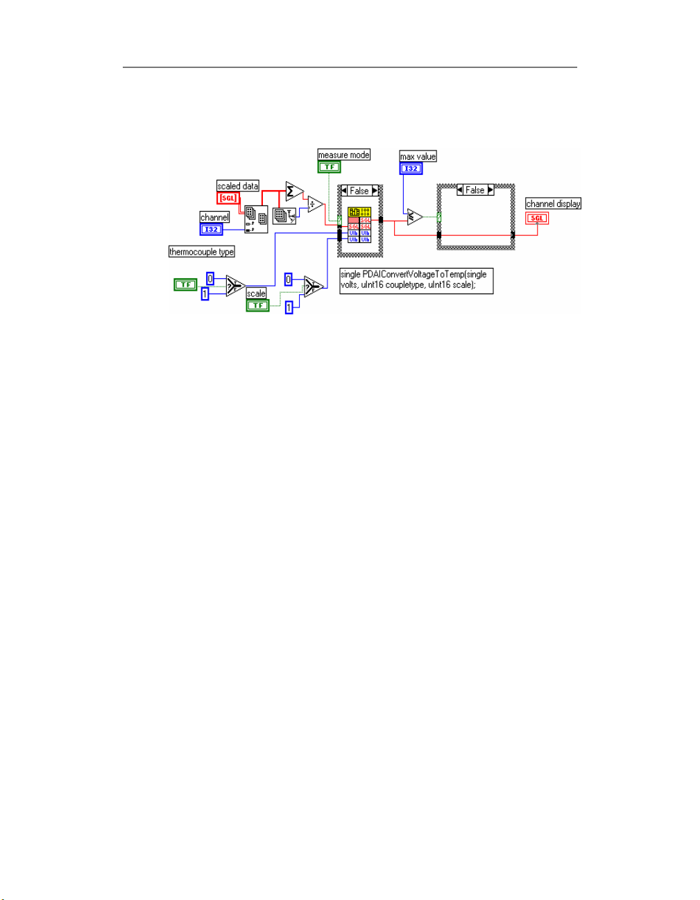
Chapter 2: Library
selected form
Block Diagram
See also
• “PD AI 16 Channels Thermocouple Rack.VI” (Example)
“
• PD AI Thermocouple Control.VI”
PD AI Read Async.VI
“PD AI Async Read.VI” incorporates all the functionality of
“PD AI Read.VI” and provides an asynchronous feature that
allows work with multiple (more than two) boars. Reads the
specified number of scans and returns the data: 'as is' in 16bits words array and 'scaled' - in output units in 4-bytes
'single' floating point numbers array. If trigger condition
specified - waits for trigger or timeout.
For speed-up operation there are two pre-allocated in “PD
AI Init Arrays.VI” arrays has to be passed to the VI call. The
size of both arrays should be equal or greater than number
of scans requested.
52
Page 65
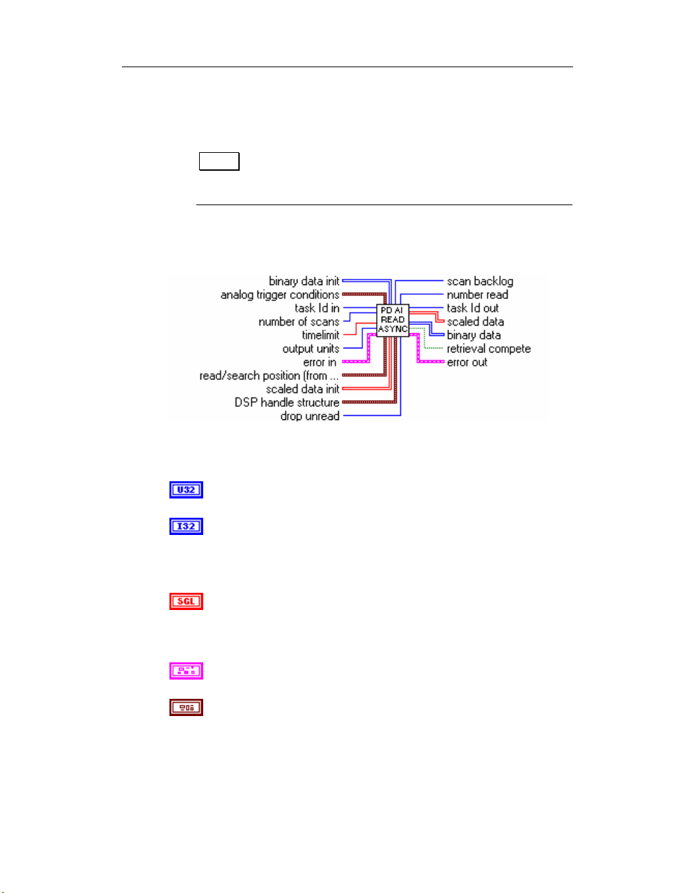
Chapter 2: Library
Special
drop unread
input allows set data read mode in
accordance with current task.
Note For asynchronous operation
timelimit
should be
zero and if analog trigger enabled timeout should
be specified in “PD AI Start VI”.
Connector Panel
Controls and Indicators
task Id in
see Common Inputs and Outputs topic for the description
number of scans input – the number of scans requested from
the driver. Use “PD AI Frame Size.VI” to find out the amount
of scans to be requested from the “PD AI Read Async.VI”
without any data loss. See Optimizing performance using the
buffer settings topic for details.
timelimit input – maximum timeout for data wait from driver.
0.0 – asynchronous operation
-1.0 – timelimit value will be calculated automatically by
driver.
error in
see Common Inputs and Outputs topic for the description
analog trigger conditions input cluster - used for set analog
trigger conditions. See cluster members description for details.
Analog trigger settings allow synchronizing the data using one
of the analog input channels (first channel in the channel list
by default) as trigger.
53
Page 66
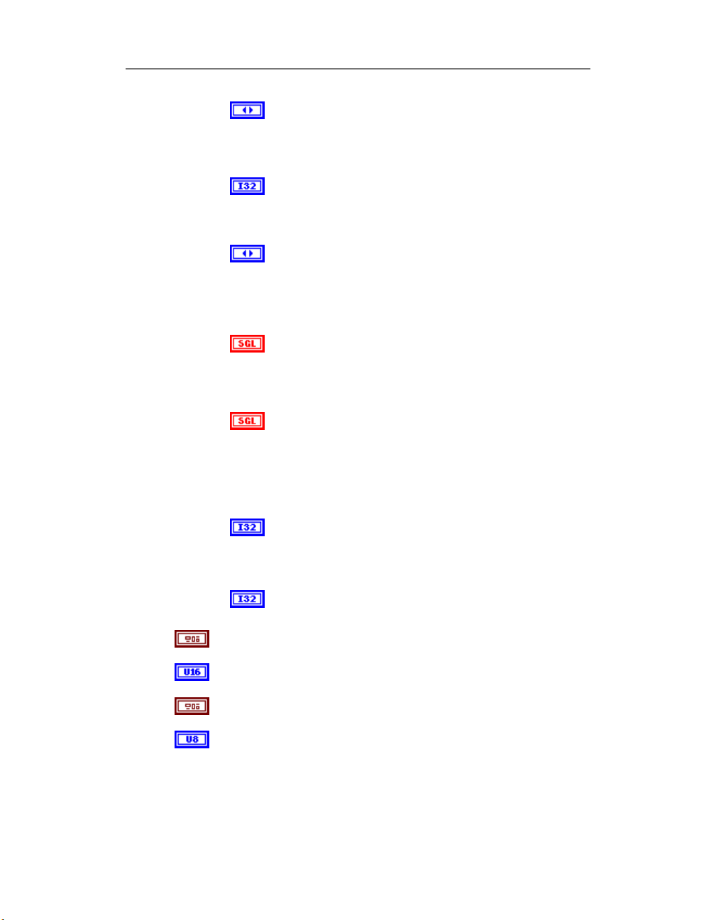
Chapter 2: Library
mode input – trigger mode :
off - clear all triggers
on - add analog trigger conditions
no change - leave trigger configuration unchanged
channel index Specify trigger channel number
For analog trigger input channel existing in channel list
could be specified in
default channel).
slope edge or slope.
0 - do not change the default setting (default
input).
1 - rising.
2 - falling.
level level (measured in Volts) which analog source
must cross for a trigger to occur. You must also
specify whether level must be crossed on a leading or
trailing slope with the edge or slope input. The default
input for level is 0.0.
hysteresis The hysteresis of the signal in Volts. The
default input and setting are 0.0. The hysteresis value
refers to a limit above or below the actual trigger level,
which will need to be surpassed before it is considered
to be a valid trigger. This compensates for the
possibility of a noise spike causing an accidental trigger
condition to be detected
skip count skip count is the number of triggers the VI
skips before triggering the acquisition.
-1 – do no change the skip count setting
0 - default – do not skip any triggers.
offset offset in scans after trigger conditions retrieved
- post trigger scan number
DSP handle structure This input is not used with PowerDAQ
boards and ignored
output units This input is not used with PowerDAQ boards and
ignored
read/search position (from mark) This input is not used with
PowerDAQ boards and ignored
drop unread Set acquisition buffer control mode:
0 - gap-free mode(used in stream to disk applications);
1 - drop the data when buffer overflow detected;
2 - drop the data up to the end of current frame in current
trigger channel
control (0 -
54
Page 67
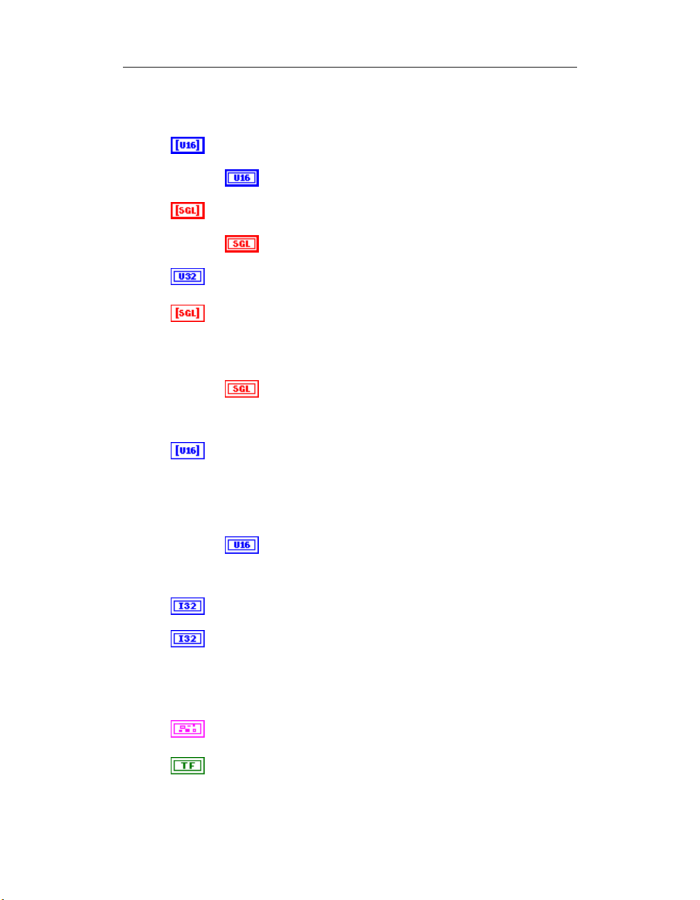
Chapter 2: Library
read;
4 - combines 1 and 2;
binary data init pre-allocated array (use “PD AI Init Arrays.VI”
to create an array)
pre-allocated array (use “PD AI Init Arrays.VI” to
create an array)
scaled data init pre-allocated array (use “PD AI Init Arrays.VI”
to create an array)
pre-allocated array (use “PD AI Init Arrays.VI” to
create an array)
task Id out
see Common Inputs and Outputs topic for the description
scaled data scaled data is a 2D array that contains analog
input data in scaled data units. The data appears in columns,
where each column contains the data for a single channel. The
second (bottom) dimension selects channel column. The first
(top) dimension selects a single data point for that channel.
scaled data: a two-dimensional array that contains
scaled analog input data if output units requests scaled
data. The first dimension is scans, the second
dimension is channels.
binary data binary data is a 2D array that contains binary
analog input data if output units requests binary data.
The data appears in columns where each column contains the
data for a single channel. The second (or bottom) dimension
selects channel column. The first (or top) dimension selects a
single data point for that channel.
binary data: a two-dimensional array that contains
binary analog input data if output units requests binary
data. The first dimension is scans, the second
dimension is channels.
number read output - number of scans that was read from
PowerDAQ board
scan backlog output - number of scans of lost data. This
output works differently in than with NI boards. The value
returned is an amount of data in scans, which was unread
from the last frame requested from the board. To determine
the amount of unread data in acquisition buffer use “PD AI
Data Count.VI”
error out
see Common Inputs and Outputs topic for the description
retrieval compete TRUE if all requested data was read from
driver
55
Page 68
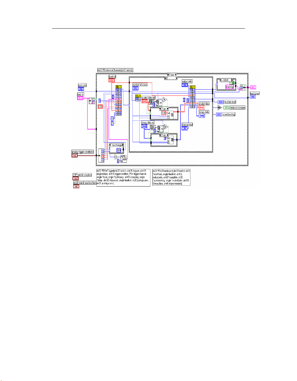
Chapter 2: Library
Block Diagram
56
See also
• “PD AI Config.VI”
• “PD AI Start.VI”
• “PD AI Read.VI”
• “PD AI Async.VI (Single-channel example)
• “PD AI Async Acquire Eight Channels.VI (Multiple-
channels example)
• “PD AI Two Boards Realtime Display.VI (Multiple boards
example)
Page 69
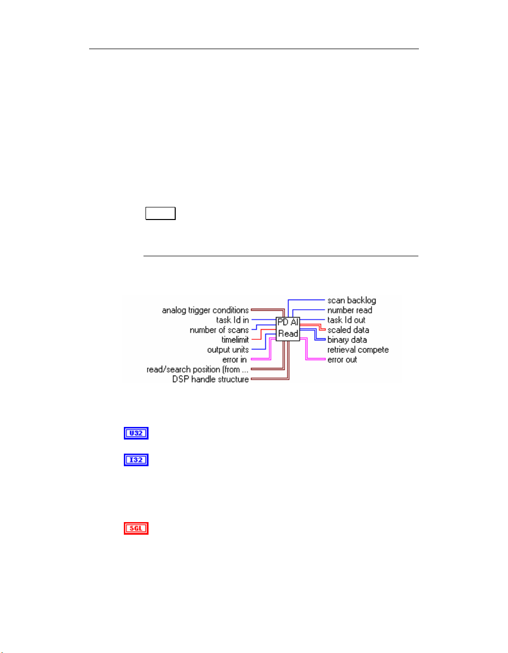
PD AI Read.vi
“PD AI Read.VI” is a main function that allows receiving the
data from the PowerDAQ board continuously. “PD AI
Read.VI” reads the specified number of scans and returns
the data: 'as is' in 16-bits words array and 'scaled' - in output
units in 4-bytes 'single' floating point numbers array. If
trigger condition specified - check for trigger or timeout.
Note That board should be properly initialized using “PD
Connector Panel
Chapter 2: Library
AI Config.VI” and acquisition started in “PD AI Start
VI”. Additional acquisition setting can be provided
in “PD AI Fine Tune.VI”
Controls and Indicators
task Id in
see Common Inputs and Outputs topic for the description
number of scans input - the number of scans requested from
the driver. Use "PD AI Frame Size.VI" to find out the amount of
scans to be requested from the "PD AI Read Async.VI" without
any data loss. See Optimizing the performance using the
buffer settings topic for details.
timelimit input - maximum timeout for data wait from driver.
0.0 - asynchronous operation
-1.0 - timelimit value will be calculated automatically by driver.
57
Page 70
Chapter 2: Library
error in
see Common Inputs and Outputs topic for the description
analog trigger conditions input cluster - used for set analog
trigger conditions. See cluster members description for details.
Analog trigger settings allow synchronizing the data using one
of the analog input channels (first channel in the channel list
by default) as trigger.
mode input - trigger mode :
off - clear all triggers
on - add analog trigger conditions
no change - leave trigger configuration unchanged
channel index Specify trigger channel number
For analog trigger input channel existing in channel list
could be specified in trigger channel control (0 default channel).
slope edge or slope.
0 - do not change the default setting (default
input).
1 - rising.
2 - falling.
level level (measured in Volts) which analog source
must cross for a trigger to occur. You must also specify
whether level must be crossed on a leading or trailing
slope with the edge or slope input. The default input
for level is 0.0.
hysteresis The hysteresis of the signal in Volts. The
default input and setting are 0.0. The hysteresis value
refers to a limit above or below the actual trigger level,
which will need to be surpassed before it is considered
to be a valid trigger. This compensates for the
possibility of a noise spike causing an accidental trigger
condition to be detected
skip count skip count is the number of triggers the VI
skips before triggering the acquisition.
-1 - do no change the skip count setting
58
Page 71
Chapter 2: Library
0 - default - do not skip any triggers.
offset offset in scans after trigger conditions retrived -
DSP handle structure This input is not used with PowerDAQ
boards and ignored
output units
post trigger scan number
size size is not used.
DSP memory handle This input is not used with
PowerDAQ boards and ignored
read/search position (from mark) This input is not used with
PowerDAQ boards and ignored
position This input is not used with PowerDAQ boards
task Id out
see Common Inputs and Outputs topic for the description
scaled data scaled data is a 2D array that contains analog input
data in scaled data units. The data appears in columns, where
each column contains the data for a single channel. The second
(bottom) dimension selects which channel column. The first
(top) dimension selects a single data point for that channel.
binary data binary data is a 2D array that contains unscaled
analog input data if output units requests binary data.
The data appears in columns where each column contains the
data for a single channel. The second (or bottom) dimension
and ignored
read offset This input is not used with PowerDAQ
boards and ignored
(